Table of Contents
Advertisement
Quick Links
Advertisement
Table of Contents

Related Manuals for Intel M50FCP1UR


Summary of Contents for Intel M50FCP1UR
- Page 1 Intel® Server System M50FCP1UR System Integration and Service Guide A guide providing instructions for the insertion and extraction of system components and available Intel accessories and spares Rev. 1.0 January 2023 Delivering Breakthrough Data Center System Innovation–Experience What’s Inside!
- Page 2 <This page intentionally left blank>...
- Page 3 Intel® Server System M50FCP1UR System Integration and Service Guide Document Revision History Date Revision Changes January 2023 Production Release...
- Page 4 You may not use or facilitate the use of this document in connection with any infringement or other legal analysis concerning Intel products described herein. You agree to grant Intel a non-exclusive, royalty-free license to any patent claim thereafter drafted which includes subject matter disclosed herein.
- Page 5 Intel recommends that the following steps be taken when performing any procedures described within this document or while performing service to any computer system.
- Page 6 Weight of the system: • Due to the weight of a system, Intel recommends carrying the system with two people supporting the system from the sides or using a mechanical lift or a cart when moving the system from one location to another.
-
Page 7: Table Of Contents
Intel® Server System M50FCP1UR System Integration and Service Guide Table of Contents 1. Introduction ................................14 Reference Documents and Support Collaterals ....................16 2. L6 Integrated System–Essential System Component Installation ..............18 Chassis Component Identification .......................... 19 System Top Cover Removal / Installation ......................19 2.2.1... - Page 8 Appendix B. Memory Population Rules ........................94 DDR5 DIMM Population Rules ..........................94 Intel® Optane™ Persistent Memory (PMem) 300 Series Module Rules ............ 94 Intel® DDR5 DIMM Support Disclaimer ......................... 96 Appendix C. System Status LED Operating States and Definition ..............97 Appendix D.
- Page 9 Intel® Server System M50FCP1UR System Integration and Service Guide Appendix G. Safety Instructions ..........................116 Appendix H. Glossary ............................... 132...
- Page 10 Intel® Server System M50FCP1UR System Integration and Service Guide List of Figures Figure 1. System Features Identification ............................14 Figure 2. Required Components for Basic System Operation ....................18 Figure 3. Chassis Component Identification ..........................19 Figure 4. System Top Cover Panel Shipping Screws ........................20 Figure 5.
- Page 11 Figure 58. Front I/O Features ................................50 Figure 59. Hot Swap Drive Bay LED Identification ........................51 Figure 60. Intel® Server Board M50FCP2SBSTD Component / Feature Identification ..........52 Figure 61. Intel® Light-Guided Diagnostics–LED Identification ....................53 Figure 62. View of POST Code Diagnostic, System ID, and System Status LEDs Area ..........53 Figure 63.
- Page 12 Figure 113. M.2 SSD Removal ................................82 Figure 114. M.2 SSD Installation ................................. 82 Figure 115. Intel® RMFBU Mounting Bracket Removal - Chassis ..................83 Figure 116. RMFBU Housing Assembly ............................83 Figure 117. Intel® RMFBU Mounting Bracket Installation ......................84 Figure 118.
- Page 13 Table 3. Drive Activity LED States ..............................51 Table 4. Intel® Optane™ PMem 300 Series Module Support....................95 Table 5. Standard DDR5 DIMMs Compatible with Intel® Optane™ PMem 300 Series Module ......... 95 Table 6. DDR5 DIMM Attributes Table for “Identical” and “Like” DIMMs ................96 Table 7.
-
Page 14: Introduction
Intel® Server System M50FCP1UR System Integration and Service Guide Introduction The Intel® Server System M50FCP1UR is a purpose-built, rack mount server that delivers power and performance in a 1U form factor. The system supports up to two 4 Gen Intel® Xeon® Scalable processors, delivering high core count and new hardware-enhanced security features. - Page 15 About This Document This document provides system integrators and service technicians with instructions for the installation and removal of system components. The document also covers available Intel accessories supported by this server system. The document is organized into two sections. The first section (Chapters 2–4) is focused on the installation of system components and accessories into an L6 or L9 integrated server system The second section (Chapters 5, 6, and appendices A-G) is focused on system service.
-
Page 16: Reference Documents And Support Collaterals
Intel® Server System M50FCP1UR System Integration and Service Guide Reference Documents and Support Collaterals For additional information and other support collaterals related to this Intel® server product, see Table 1. Listed documents and utilities can be downloaded from the following Intel websites or can be ordered through a local Intel support representative. - Page 17 Intel® Data Center Manager (Intel® DCM) information Intel® Data Center Manager (Intel® DCM) Console User Guide https://software.intel.com/content/www/us/en/develop/download/dcm- Public user-guide.html Note: Intel Confidential documents are made available under a nondisclosure agreement (NDA) with Intel and must be ordered through your local Intel representative.
-
Page 18: L6 Integrated System-Essential System Component Installation
300 series modules Power supply – two required for redundancy • If your Intel server system came preinstalled with all listed components, then skip this chapter and go to Chapter 3 for installation procedures associated with all other system options and accessories. -
Page 19: Chassis Component Identification
Intel® Server System M50FCP1UR System Integration and Service Guide Chassis Component Identification The following figure shows the chassis components. System Fans Figure 3. Chassis Component Identification System Top Cover Removal / Installation The system top cover consists of two panels, one over the front half of the system, and one over the back half of the system. -
Page 20: Figure 4. System Top Cover Panel Shipping Screws
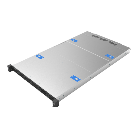
Intel® Server System M50FCP1UR System Integration and Service Guide Figure 4. System Top Cover Panel Shipping Screws The system ships from the factory with the front cover panel and back cover panel screwed to the chassis. A total of four screws, one on each side of the front cover panel, and one on each side of the back cover panel, need to be removed to detach both top cover panels from the chassis. -
Page 21: System Cover Installation
1. Carefully align and set the top cover panel on top of the chassis. Then, slide it inwards until it locks into place (see Letter A). Shipping Note: When transporting the server system, Intel recommends installing the four top cover screws before shipping. -
Page 22: Figure 7. 1U Heat Sinks
Intel® Server System M50FCP1UR System Integration and Service Guide Figure 7. 1U Heat Sinks Caution: Fin edges of the processor heat sink are very sharp. Intel recommends wearing thin ESD protective gloves when handling the PHM during the following procedures. -
Page 23: Figure 10. Processor Carrier Clip Identifier Markings
Intel® Server System M50FCP1UR System Integration and Service Guide Each type of processor carrier clip will include identifier markings as shown in Figure 10. Match the processor clip to the clip identifier that is etched on the processor heat spreader, as shown in Figure 10. -
Page 24: Processor Heat Sink Module (Phm) Assembly
Intel® Server System M50FCP1UR System Integration and Service Guide The procedures described in the following sections must be followed in the order specified to assemble the PHM and install it to the server board. These instructions assume that all PHM components are new, and the Thermal Interface Material (TIM) is already applied to the bottom of the heat sink. -
Page 25: Figure 14. Removing Heat Sink From Its Packaging
Intel® Server System M50FCP1UR System Integration and Service Guide Figure 14. Removing Heat Sink from its Packaging 4. Remove the heat sink from its packaging. To avoid damage to the heat sink, grasp it by its narrower top and bottom edges. -
Page 26: Processor Installation
Intel® Server System M50FCP1UR System Integration and Service Guide 8. Align Pin 1 indicator of processor carrier clip with the corner cut-out on the heat sink. For the EVAC heat sink, align the processor carrier clip and the heat sink as shown in... -
Page 27: Figure 18. Phm Alignment With Socket Assembly
Intel® Server System M50FCP1UR System Integration and Service Guide Figure 18. PHM Alignment with Socket Assembly 1. Set all four anti-tilt wires on the heat sink to the inward position (see Letter A in Figure 19). 2. Align the Pin 1 indicators of the processor carrier clip and processor with the Pin 1 indicator on the bolster plate located around the processor socket. -
Page 28: Figure 20. Tighten Heat Sink Extension Fasteners
Intel® Server System M50FCP1UR System Integration and Service Guide Figure 20. Tighten Heat Sink Extension Fasteners 6. Using a T30 Torx* screwdriver, tighten the heat sink fasteners to 8 in-lb. No specific sequence is needed for tightening. Important: A processor socket cover should be installed onto any unpopulated processor socket. Do not... -
Page 29: Memory Module Installation
The Intel® Server System M50FCP1UR supports DDR5 standard RDIMMs 3DS-RDIMMs, and 9x4 RDIMMs. In addition, the server board supports Intel® Optane™ persistent memory 300 series modules (also known as, Intel® Optane™ PMem). DDR5 DIMM and Intel® Optane® PMem devices are commonly referred to as “memory module” in the following procedure. Notes: DIMM blanks should only be removed when installing a memory module in its place. -
Page 30: Power Supply Module Installation
6. Ensure that the ejection tabs are firmly in place (see Letter E). 7. Repeat the procedure for each memory module to be installed. Note: Intel® Optane™ PMem devices require additional steps to enable and configure them. Refer to the appropriate Intel® Optane™ PMem documentation to complete the installation process. -
Page 31: System Options / Accessory Kit Installation
Intel® Server System M50FCP1UR System Integration and Service Guide System Options / Accessory Kit Installation This chapter provides instructions for the integration of system options and other Intel accessories. If your integrated Intel server system did not come preinstalled with processors, memory, or power supplies,... -
Page 32: System Cover Installation
1. Carefully align and set the top cover panel on top of the chassis. Then, slide it inwards until it locks into place. See Letter A. Shipping Note: When transporting the server system, Intel recommends installing the four top cover screws before shipping. -
Page 33: System Cable Routing
Intel® Server System M50FCP1UR System Integration and Service Guide System Cable Routing All internal cables routed between the back of the system and the front of the system must be routed using the cable channel located between the right air baffle and the right chassis sidewall. See Figure 27. -
Page 34: Riser Card / Add-In Card Installation
Intel® Server System M50FCP1UR System Integration and Service Guide Riser Card / Add-in Card Installation The Intel® Server System M50FCP1UR supports various riser card options. Depending on the system configuration, your system may or may not come pre-configured with riser card options installed. This section provides assembly and installation instructions for systems that require riser card installation. -
Page 35: Riser Card Bracket Removal
Intel® Server System M50FCP1UR System Integration and Service Guide 3.3.1 Riser Card Bracket Removal As shown in the previous figures, there are multiple types of riser card brackets included with the system. The instructions for installation are the same for each. -
Page 36: Pcie* Add-In Card Installation
Intel® Server System M50FCP1UR System Integration and Service Guide 1. Locate and carefully unpack the riser card. Hold the riser card by its edges. To NOT touch the gold edge connector pins. 2. Align the riser card to the threaded standoffs on the mounting bracket. -
Page 37: Riser Card Assembly Installation-For All Riser Assemblies
Intel® Server System M50FCP1UR System Integration and Service Guide 1. If the riser card assembly (bracket and riser card) is still inside the system, remove it from the system following instructions in Section 3.2.1. 2. Remove the screw (see Letter A) holding the filler plate to the bracket. Remove the filler plate. See Letter B. -
Page 38: Front Drive Installation
Front Drive Installation The Intel® Server System M50FCP1UR has front drive bays that only support 2.5” SSDs. Supported SSDs can have a drive height of 7mm or 15mm. 7mm must be attached to a supplied drive mounting bracket to be compatible with the front drive bays. -
Page 39: Drive Blank Removal
Intel® Server System M50FCP1UR System Integration and Service Guide 3.4.1 Drive Blank Removal Each drive carrier includes a 2.5” drive blank. Drive blanks should only be removed when replacing it with an SSD. Figure 38. Drive Blank Removal 1. Press the button on the drive extraction lever to release it. See Letter A. -
Page 40: 2.5" Ssd Drive Installation
Intel® Server System M50FCP1UR System Integration and Service Guide Figure 40. Attaching the Drive Blank to 7 mm SSD 4. Slide the SSD drive into SSD mounting bracket. See Figure Important: To avoid damaging the SSD connector, insert the drive into the supplied blank in the direction shown. -
Page 41: Ethernet Network Adapter For Ocp* Installation
2. Align and insert the drive into the drive bay. See Letter A. Note: Intel recommends holding the drive with one hand while holding the lever with the other hand. 3. Slide the drive into the drive bay until it is fully seated within the drive interface connector on the backplane (see Letter B). -
Page 42: Ocp* Adapter Bay Filler Removal / Installation
Intel® Server System M50FCP1UR System Integration and Service Guide 3.5.1 OCP* Adapter Bay Filler Removal / Installation Figure 43. OCP* Adapter Bay Filler Removal Remove the filler insert to install an OCP add-in card. 1. Loosen the thumb screw on the right side of the filler (see Letter A). -
Page 43: Ocp* Adapter With Pull Tab Installation
Intel® Server System M50FCP1UR System Integration and Service Guide 3.5.2 OCP* Adapter with Pull Tab Installation Figure 45. OCP* Adapter with Pull Tab Installation 1. Align the OCP adapter with the open OCP bay slot and slide forward until the connectors make secure contact (see Letter A). -
Page 44: M.2 Storage Device Installation
Intel® Server System M50FCP1UR System Integration and Service Guide Figure 47. OCP* Adapter with Internal Lock Installation 1. Power off the system and disconnect the system power cords. 2. Remove the system top cover (see Section 3.1.1) 3. If present, remove the riser card assembly above the OCP adapter area, (see Section 3.2.1). -
Page 45: Trusted Platform Module (Tpm) Installation
Intel® Server System M50FCP1UR System Integration and Service Guide Figure 49. M.2 SSD Installation 1. Power off the system and disconnect the system power cords. 2. Remove the system top cover (see Section 3.1.1). 3. Remove the riser card #1 bracket from the system (see Section 3.2.1). -
Page 46: Intel® Raid Maintenance Free Backup Unit (Rmfbu) Installation
3.1.2). Intel® RAID Maintenance Free Backup Unit (RMFBU) Installation This section provides instructions to install an RMFBU bracket and assembly in the system. Refer to the Intel® Server M50FCP Family Configuration Guide for available Intel RAID card options. Required Tools and Supplies •... -
Page 47: Figure 53. Intel® Rmfbu Mounting Plate Installation
Intel® Server System M50FCP1UR System Integration and Service Guide 4. Insert the RMFBU super capacitor into the plastic housing with the cable protruding out from one of the cable routing openings. Choose the opening that results in the best cable routing to the RAID module. -
Page 48: System Software Updates And Configuration
BIOS Firmware External Product Specification (EPS)–Intel NDA required • Integrated Baseboard Management Controller Firmware External Product Specification (EPS)–Intel • NDA Required For guidelines and overview on BIOS Boot Menu, Setup, and hot keys, see the Intel® Server Board M50FCP2SBSTD Technical Product Specification. -
Page 49: System Service-System Features Overview
System Service–System Features Overview This chapter provides service personnel a reference to identify and locate the features associated with the Intel® Server System M50FCP1UR. For more information, refer to Intel® Server System M50FCP2UR Technical Product Specifications. Front Drive Bay Options Figure 54. -
Page 50: Figure 57. Front Control Panel Features
Intel® Server System M50FCP1UR System Integration and Service Guide Figure 57. Front Control Panel Features Figure 58. Front I/O Features... -
Page 51: Drive Bay Led Identification
Intel® Server System M50FCP1UR System Integration and Service Guide Drive Bay LED Identification Figure 59. Hot Swap Drive Bay LED Identification Table 2. Drive Status LED States LED State Drive Status No access and no fault Amber Solid on Hard drive fault has occurred... -
Page 52: Server Board Features
Intel® Server System M50FCP1UR System Integration and Service Guide Server Board Features The following figure provides a general overview of the physical server board, identifying key feature and component locations. Figure 60. Intel® Server Board M50FCP2SBSTD Component / Feature Identification... -
Page 53: Figure 61. Intel® Light-Guided Diagnostics-Led Identification
Intel® Server System M50FCP1UR System Integration and Service Guide The server board includes LEDs to identify system status and/or indicate a component fault. The following figures identify the diagnostic LEDs and their location on the server board. Figure 61. Intel® Light-Guided Diagnostics–LED Identification... -
Page 54: System Configuration And Recovery Jumpers
The server board includes several jumper blocks that can be used to configure, protect, or recover specific features of the server board. The following figure identifies the location of each jumper block on the server board. For more information on the jumpers, see the Intel® Server Board M50FCP2SBSTD Technical Product Specification (TPS). -
Page 55: System Service And Fru Replacement
Intel® Server System M50FCP1UR System Integration and Service Guide System Service and FRU Replacement This chapter provides instructions for replacement of system components considered to be field replaceable (FRU). Only system features that are identified as hot-swappable can be replaced while the system remains operational. -
Page 56: System Top Cover Removal / Installation
Intel® Server System M50FCP1UR System Integration and Service Guide System Top Cover Removal / Installation The system top cover consists of two panels, one over the front half of the system and one over the back half of the system. To maintain system thermals, both top cover panels must be in place when the system is operational. -
Page 57: System Cover Installation
1. Carefully align and set the top cover panel on top of the chassis. Then, slide it inwards until it locks into place (see Letter A). Shipping Note: When transporting the server system, Intel recommends installing the four top cover screws before shipping. -
Page 58: System Fan Replacement
Note: a faulty system fan with dual rotors may still have a functional rotor. Because fan rotors spin at very high speeds, extreme caution should be taken when performing a hot replacement of a system fan. For safety, Intel recommends replacing a faulty system fan with the system powered off whenever possible. Required Tools and Supplies Anti-static wrist strap and conductive workbench pad (recommended) •... -
Page 59: Figure 69. Individual Fan Installation
Intel® Server System M50FCP1UR System Integration and Service Guide Figure 69. Individual Fan Installation 5. Locate and unwrap the replacement fan. 6. Ensure that the empty fan slot within the assembly housing is clear of any cables. 7. Align the fan connector with the server board connector, and carefully lower the fan into the fan assembly housing. -
Page 60: Memory Module Replacement
The following figures show standard DDR5 DIMMs, but the physical replacement procedure is the same for both standard DDR5 DIMMs and Intel® Optane™ PMem modules. DDR5 DIMM and Intel Optane PMem devices are commonly referred to as “memory module” in the following instructions. -
Page 61: Figure 71. Memory Module Installation
12. Reinstall the system top cover (see Section 6.1.2). Note: Replacing Intel® Optane™ PMem 300 series modules require additional steps to enable and configure them. Refer to the appropriate Intel® Optane™ PMem 300 series documentation to complete the installation process for these devices. -
Page 62: Power Supply Replacement
Intel® Server System M50FCP1UR System Integration and Service Guide Power Supply Replacement Required Tools and Supplies Anti-static wrist strap and conductive workbench pad (recommended) • Caution: The power supply is only hot-swappable (system does not have to be powered down) if the system has both power supplies installed, and the system is still operational with a single functional power supply. -
Page 63: Processor Replacement
Note: The following sections show the EVAC heat sink in the figures. The procedures described apply to both heat sink types. Caution: Fin edges of the processor heat sink are very sharp. Intel recommends wearing thin ESD protective gloves when handling the PHM during the following procedures. -
Page 64: Processor Heat Sink Module (Phm) And Processor Removal
Intel® Server System M50FCP1UR System Integration and Service Guide Each type of processor carrier clip will have an identifier marking: E1A or E1B. The processor will have an etch on its heat spreader identifying the supported type of carrier clip. Match the processor to the supported processor clip as shown in Figure 76. -
Page 65: Figure 78. Reinstall The Socket Cover
Caution: If debris is observed, blow it away gently with an air blower. Do not use tweezers or any other hard tools to remove it manually. If reinstalling the processor later, then Intel highly recommends installing the processor socket protective cover that shipped with the system to prevent possible pin damage while the socket is not populated. -
Page 66: Processor Heat Sink Module (Phm) Assembly
Intel® Server System M50FCP1UR System Integration and Service Guide Figure 80. Processor Carrier Clip Removal from PHM Assembly 12. Return the lever to the original position (see Letter C). 13. Unlatch the tab on each corner of the processor carrier clip to release it from the heat sink (see Letter 14. -
Page 67: Figure 82. Installing Processor Carrier Clip Onto Processor-Part 2
Intel® Server System M50FCP1UR System Integration and Service Guide Figure 82. Installing Processor Carrier Clip onto Processor–Part 2 3. Gently press down on two opposite sides of the carrier clip until it clicks into place. Repeat with the other two sides (See Figure 82). -
Page 68: Processor Installation
Intel® Server System M50FCP1UR System Integration and Service Guide Figure 85. Pin 1 Indicator of Processor Carrier Clip 8. Carefully lift and turn over the heat sink. 9. Align the Pin 1 indicator of the processor carrier clip with the corner cut-out on the heat sink (See Figure 85. -
Page 69: Figure 87. Phm Alignment With Socket Assembly
Intel® Server System M50FCP1UR System Integration and Service Guide Figure 87. PHM Alignment with Socket Assembly 2. Set anti-tilt wires on all four corners of the heat sink to the inward position (see Letter A in Figure 88). 3. Align the Pin 1 indicators of the processor carrier clip and processor with the Pin 1 indicator on the... -
Page 70: Figure 89. Tighten Heat Sink Extension Fasteners
Intel® Server System M50FCP1UR System Integration and Service Guide Figure 89. Tighten Heat Sink Extension Fasteners 7. Using a T30 Torx* screwdriver, tighten the heat sink fasteners to 8 in-lb. No specific sequence is needed for tightening. 8. Reinstall the system top cover (see Section 6.1.2). -
Page 71: Riser Card Replacement
Intel® Server System M50FCP1UR System Integration and Service Guide Riser Card Replacement This section provides instructions for the replacement of a riser card. Required Tools and Supplies • Replacement riser card accessory kit Anti-static wrist strap and conductive workbench pad (recommended) •... -
Page 72: Figure 92. Add In Card Removal From Bracket
Intel® Server System M50FCP1UR System Integration and Service Guide Figure 92. Add in Card Removal from Bracket Remove the screw that secures the add-in card to the riser card bracket (see Letter A). • • Carefully remove the add-in card to the riser card bracket (see Letter B). -
Page 73: Figure 95. Add-In Card Installation
Intel® Server System M50FCP1UR System Integration and Service Guide Figure 95. Add-in Card Installation 10. Reinstall the add-in card into the riser card 11. Using the fastener screws, secure the add-in card to the riser card bracket (see Letter B). Tighten to 5 in-lb. -
Page 74: Figure 97. Back Panel Shipping Screw Locations
Intel® Server System M50FCP1UR System Integration and Service Guide 18. Reinstall the system top cover (see Section 6.1.2). Note: To transport a fully integrated system, Intel highly recommends the system include four shipping screws (not included) installed to the system back panel (see Figure 97). -
Page 75: Front Drive Replacement
Front Drive Replacement The Intel® Server System M50FCP1UR has front drive bays that only support 2.5” SSDs. Supported SSDs can have a drive height of 7mm or 15mm. 7mm must be attached to a supplied drive mounting bracket to be compatible with the front drive bays. -
Page 76: Mm 2.5" Ssd Drive Replacement
Intel® Server System M50FCP1UR System Integration and Service Guide 1. Press the button on the drive extraction lever to release it. See Letter A. 2. Using the lever, pull the drive rail out from the drive bay as far as it allows (see Letter B). -
Page 77: 2.5" Ssd Drive Installation
Intel® Server System M50FCP1UR System Integration and Service Guide 6.7.3 2.5” SSD Drive Installation The procedure to install a drive into a drive bay is the same for both 7mm (drive + bracket) and 15mm SSDs. Note the drive orientation before installing the drive into the drive bay. Installing a drive incorrectly can damage the interface connectors of the drive and the backplane. -
Page 78: 2.5" Drive Mounting Rail Replacement
Intel® Server System M50FCP1UR System Integration and Service Guide Note: Intel recommends holding the drive with one hand while holding the lever with the other hand. 4. Slide the drive forward until it is fully connected with the backplane (see Letter B). -
Page 79: Figure 107. Installing Drive Mounting Rail
Intel® Server System M50FCP1UR System Integration and Service Guide Using a flat head screwdriver, carefully twist the locking tab inward to unlock the drive rail from • the drive bay (see Letter A). Gently lift the drive rail from the alignment slot and pull it out and away from the drive bay. -
Page 80: Ethernet Network Adapter For Ocp* Replacement
Intel® Server System M50FCP1UR System Integration and Service Guide Ethernet Network Adapter for OCP* Replacement This section provides instructions for replacement of an OCP* add-in card. OCP add-in cards will have one of two possible methods to secure the card within the OCP bay. Refer to the section that supports the card type to be replaced. -
Page 81: Ocp* Adapter With Internal Lock Replacement
Intel® Server System M50FCP1UR System Integration and Service Guide 6.9.2 OCP* Adapter with Internal Lock Replacement All L6 and L9 integrated systems come with an internal lock on the internal OCP mounting rail. This lock is a piece of blue plastic. The OCP rail in the system has a dedicated space to accommodate the lock. The lock can be mounted on the rail in two different orientations. -
Page 82: 6.10 M.2 Storage Device Replacement
Intel® Server System M50FCP1UR System Integration and Service Guide 6. Squeeze the two hooks of the internal lock and pull it out (see Letter A). 7. Align the OCP adapter with the open OCP* bay slot and slide forward until the connectors make secure contact (see Letter B). -
Page 83: 6.11 Intel® Raid Maintenance Free Backup Unit (Rmfbu) Replacement
Intel® Server System M50FCP1UR System Integration and Service Guide 9. Align and insert the M.2 SSD with the connector on the server board. See Letter A. 11. Using the screw, secure the SSD to the mounting stand-off on the server board (see Letter B). -
Page 84: Figure 117. Intel® Rmfbu Mounting Bracket Installation
Intel® Server System M50FCP1UR System Integration and Service Guide 7. Insert the RMFBU super capacitor into the plastic housing with the cable protruding out from one of the cable routing openings. Choose the opening resulting in the best cable routing to the RAID module. -
Page 85: 6.12 Backplane Replacement
Intel® Server System M50FCP1UR System Integration and Service Guide 6.12 Backplane Replacement Depending on the system configuration, the Intel® Server System M50FCP1UR includes either a 4 x 2.5” backplane or 12 x 2.5” backplane. This section provides the procedures necessary to replace both types. -
Page 86: Figure 119. 4 X 2.5" Backplane Installation
Intel® Server System M50FCP1UR System Integration and Service Guide Figure 119. 4 x 2.5” Backplane Installation 7. Locate and carefully unpack the replacement backplane. Note: Hold the backplane by its edges. Do not touch any components mounted to the backplane. -
Page 87: 2.5" Backplane Replacement
Intel® Server System M50FCP1UR System Integration and Service Guide 6.12.2 12 X 2.5” Backplane Replacement Required Tools and Supplies • Intel backplane kit • Anti-static wrist strap and conductive anti-static wrist strap and conductive workbench pad (recommended) Phillips* head screwdriver #1 •... -
Page 88: Figure 121. 12 X 2.5" Backplane Installation
Intel® Server System M50FCP1UR System Integration and Service Guide Figure 121. 12 x 2.5” Backplane Installation 7. Locate and carefully unpack the replacement backplane. 8. Note: Hold the backplane by its edges. Do not touch any components mounted to the backplane. -
Page 89: 6.13 System Battery Replacement
Intel® Server System M50FCP1UR System Integration and Service Guide 6.13 System Battery Replacement Required Tools and Supplies Compatible CR2032 lithium battery • Anti-static wrist strap and conductive workbench pad (recommended) • Figure 122. Replacing the System Battery 1. Power off the system 2. -
Page 90: 6.14 Server Board Replacement
Intel® Server System M50FCP1UR System Integration and Service Guide 6.14 Server Board Replacement Required Tools and Supplies Intel® Server Board M50FCP2SBSTD spare • Anti-static wrist strap and conductive workbench pad (recommended) • • Phillips* head screwdriver #2 Figure 123. Server Board Removal 1. -
Page 91: Figure 124. Server Board Installation
Intel® Server System M50FCP1UR System Integration and Service Guide 8. If present, remove the OCP add-in card 9. If present, remove all options installed onto the server board, including: TPM Module and M.2 SSDs 10. Remove processors (see Section 6.5). - Page 92 Intel® Server System M50FCP1UR System Integration and Service Guide 22. Secure the server board to the chassis using all the fasteners removed in Step 14. (See Letter B), Tighten to 5 in-lb. 23. Place and secure the right and left metal air baffles to edges of the server board. Tighten to 5 in-lb.
-
Page 93: Appendix A. Getting Help
Intel Configure to Order tool. If a solution cannot be found at Intel’s support site, submit a service request via Intel’s online service center at https://supporttickets.intel.com/servicecenter?lang=en-US. In addition, you can also view previous support requests. (Login required to access previous support requests) Contact an Intel support representative using one of the support phone numbers available at https://www.intel.com/content/www/us/en/support/contact-support.html... -
Page 94: Appendix B. Memory Population Rules
For multiple DIMMs per channel: o Only one Intel Optane PMem 300 series module is supported per memory channel. o Intel Optane PMem 300 series modules are only supported in memory module slot 2 (black slot) when mixed with standard RDIMM, 3DS-RDIMM, 9x4 RDIMM. -
Page 95: Table 4. Intel® Optane™ Pmem 300 Series Module Support
Intel® Server System M50FCP1UR System Integration and Service Guide Ensure that the same DDR5 DIMM type and capacity is used for each DDR5 + Intel Optane PMem 300 • series module combination. Minimum of one DDR5 DIMM per IMC (IMC 0, IMC 1, IMC 2 and IMC 3) for each installed processor. -
Page 96: Intel® Ddr5 Dimm Support Disclaimer
However, Intel may ship back a validated “Like” DIMM. A “Like” DIMM may be from the same vendor but may not be the same revision # or model #, or it may be an Intel validated DIMM from a different vendor. -
Page 97: Appendix C. System Status Led Operating States And Definition
Intel® Server System M50FCP1UR System Integration and Service Guide Appendix C. System Status LED Operating States and Definition The server board includes a bi-color System Status LED. The system status LED on the server board is tied directly to the system status LED on the front panel (if present). This LED indicates the current health of the server system. - Page 98 Intel® Server System M50FCP1UR System Integration and Service Guide LED State System State BIOS Status Description • Critical threshold crossed–Voltage, temperature (including HSBP temp), input power to power supply, output current for main power rail from power supply and PROCHOT (Therm Ctrl) sensors.
-
Page 99: Appendix D. Post Code Diagnostic Led Decoder
Intel® Server System M50FCP1UR System Integration and Service Guide Appendix D. POST Code Diagnostic LED Decoder As an aid in troubleshooting a system hang that occurs during a system POST process, the server board includes a bank of eight POST code diagnostic LEDs on the back edge of the server board. -
Page 100: D.1 Early Post Memory Initialization Mrc Diagnostic Codes
Intel® Server System M50FCP1UR System Integration and Service Guide Upper nibble bits = 1010b = Ah; Lower nibble bits = 1100b = Ch; the two Hex Nibble values are combined to create a single ACh POST Progress Code. D.1 Early POST Memory Initialization MRC Diagnostic Codes... -
Page 101: D.2 Bios Post Progress Codes
Intel® Server System M50FCP1UR System Integration and Service Guide Table 10. MRC Fatal Error Codes Upper Nibble Lower Nibble Post Code Description (Hex) No usable memory error 01h = No memory was detected from SPD read, or invalid config that causes no operable memory. - Page 102 Intel® Server System M50FCP1UR System Integration and Service Guide Post Upper Nibble Lower Nibble Code Description (Hex) Program final IO SAD setting Protocol layer and other uncore settings Transition links to full speed operation Coherency settings KTI initialization done Pre-EFI Initialization (PEI) Phase...
- Page 103 Intel® Server System M50FCP1UR System Integration and Service Guide Post Upper Nibble Lower Nibble Code Description (Hex) Check RAS support PMem ADR Init Internal Use Memory Late Init Determine MRC boot mode MKTME Early Init SGX Early Init Memory Margin Test...
- Page 104 Intel® Server System M50FCP1UR System Integration and Service Guide Post Upper Nibble Lower Nibble Code Description (Hex) DXE SCSI enable DXE SETUP start DXE SETUP input wait DXE Ready to Boot DXE Legacy Boot DXE Exit Boot Services RT Set Virtual Address Map Begin...
-
Page 105: Appendix E. Post Code Errors
Pause” option setting in the BIOS Setup does not affect this error. Note: The POST error codes in the following table are common to all current generation Intel® server platforms. Features present on a given server board/system determine which of the listed error codes... -
Page 106: Table 12. Post Error Messages And Handling
Intel® Server System M50FCP1UR System Integration and Service Guide Table 12. POST Error Messages and Handling Error Code Error Message Action Message Type 0012 System RTC date/time not set Major 0048 Password check failed Put right password. Major 0140 PCI component encountered a PERR error... - Page 107 Intel® Server System M50FCP1UR System Integration and Service Guide Error Code Error Message Action Message Type 8523 Memory failed test/initialization CPU0_DIMM_B1 Remove the inactivated DIMM. Major 8524 Memory failed test/initialization CPU0_DIMM_B2 Remove the inactivated DIMM. Major 8525 Memory failed test/initialization CPU0_DIMM_B3 Remove the inactivated DIMM.
- Page 108 Intel® Server System M50FCP1UR System Integration and Service Guide Error Code Error Message Action Message Type 8551 Memory inactivated.CPU0_DIMM_F3 Remove the inactivated DIMM. Major 8552 Memory inactivated.CPU0_DIMM_G1 Remove the inactivated DIMM. Major 8553 Memory inactivated.CPU0_DIMM_G2 Remove the inactivated DIMM. Major 8554 Memory inactivated.CPU0_DIMM_G3...
- Page 109 Intel® Server System M50FCP1UR System Integration and Service Guide Error Code Error Message Action Message Type Memory encountered a Serial Presence Detection(SPD) Major 8571 failure.CPU0_DIMM_F3 Memory encountered a Serial Presence Detection(SPD) Major 8572 failure.CPU0_DIMM_G1 Memory encountered a Serial Presence Detection(SPD)
- Page 110 Intel® Server System M50FCP1UR System Integration and Service Guide Error Code Error Message Action Message Type 85D4 Memory inactivated.CPU1_DIMM_E1 Remove the inactivated DIMM. Major 85D5 Memory inactivated.CPU1_DIMM_E2 Remove the inactivated DIMM. Major 85D6 Memory inactivated.CPU1_DIMM_E3 Remove the inactivated DIMM. Major 85D7 Memory inactivated.CPU1_DIMM_F1...
-
Page 111: Post Error Beep Codes
Codes that are common across all Intel server boards and systems that use same generation chipset are listed in the following table. Each digit in the code is represented by a sequence of beeps whose count is equal to the digit. -
Page 112: Processor Initialization Error Summary
Intel® Server System M50FCP1UR System Integration and Service Guide Processor Initialization Error Summary The following table describes mixed processor conditions and actions for all Intel® server boards and Intel® server systems designed with the Intel® Xeon® Scalable processor family architecture. The errors fall into one of the following categories: •... -
Page 113: Appendix F. System Packaging Assembly Instructions
Intel® Server System M50FCP1UR System Integration and Service Guide Appendix F. System Packaging Assembly Instructions The original Intel packaging, in which the server system is delivered, is designed to provide protection to a fully configured system and was tested to meet ISTA (International Safe Transit Association) Test Procedure 3A (2008). - Page 114 Intel® Server System M50FCP1UR System Integration and Service Guide 2. Place the front cushion (iPN K65031-001) on the left end of the inner box. Place the rear cushion (K65006-001) on the right end of the inner box. Then, place bottom foam K75566-001 in the middle. See the following figure.
- Page 115 Intel® Server System M50FCP1UR System Integration and Service Guide 5. Place the accessory kit box (iPN H49469-001) in the center foam cushion. Place the extension rails in the two narrow foam cavities. See the following figure. 6. Close the inner box.
- Page 116 Intel® Server System M50FCP1UR System Integration and Service Guide Appendix G. Safety Instructions WARNING: English (US) The power supply in this product contains no user-serviceable parts. There may be more than one supply in this product. Refer servicing only to qualified personnel.
- Page 117 Intel® Server System M50FCP1UR System Integration and Service Guide For proper cooling and airflow, always reinstall the chassis covers before turning on the system. Operating the system without the covers in place can damage system parts. To install the covers: 1.
- Page 118 Intel® Server System M50FCP1UR System Integration and Service Guide ОСТОРОЖНО: русский Блок питания данного изделия не содержит деталей, подлежащих обслуживанию пользователем. В этом изделии может быть несколько блоков питания. Обслуживание должно выполняться только квалифицированным персоналом. Не модифицируйте и не используйте прилагаемый кабель питания, если он не соответствует...
- Page 119 Intel® Server System M50FCP1UR System Integration and Service Guide ОСТОРОЖНО: русский (продолжение) Для обеспечения надлежащего охлаждения и воздушного потока всегда устанавливайте на место крышки корпуса перед включением системы. Работа системы без установленных крышек может привести к повреждению компонентов системы. Чтобы установить крышки, выполните следующие...
- Page 120 Intel® Server System M50FCP1UR System Integration and Service Guide УВАГА! Українська Джерело живлення в цьому виробі не містить жодних частин, які користувачі могли б обслуговувати самостійно. Цей виріб може містити більше одного джерела живлення. Обслуговувати його може виключно кваліфікований персонал.
- Page 121 Intel® Server System M50FCP1UR System Integration and Service Guide УВАГА! Українська (продовження) Для правильного охолодження та вентиляції завжди повертайте на місце кришки корпусу перед увімкненням системи. Робота системи без кришок може пошкодити деталі системи. Щоб установити кришки, виконайте такі дії: Спочатку...
- Page 122 Intel® Server System M50FCP1UR System Integration and Service Guide AVERTISSEMENT: Français Le bloc d'alimentation de ce produit ne contient aucune pièce pouvant être réparée par l'utilisateur. Ce produit peut contenir plus d'un bloc d'alimentation. Veuillez contacter un technicien qualifié en cas de problème.
- Page 123 Intel® Server System M50FCP1UR System Integration and Service Guide Afin de permettre le refroidissement et l’aération du système, réinstallez toujours les panneaux du boîtier avant de mettre le système sous tension. Le fonctionnement du système en l’absence des panneaux risque d’endommager ses pièces. Pour installer les panneaux, procédez comme suit:...
- Page 124 Intel® Server System M50FCP1UR System Integration and Service Guide WARNUNG: Deutsch Benutzer können am Netzgerät dieses Produkts keine Reparaturen vornehmen. Das Produkt enthält möglicherweise mehrere Netzgeräte. Wartungsarbeiten müssen von qualifizierten Technikern ausgeführt werden. Versuchen Sie nicht, das mitgelieferte Netzkabel zu ändern oder zu verwenden, wenn es sich nicht genau um den erforderlichen Typ handelt.
- Page 125 Intel® Server System M50FCP1UR System Integration and Service Guide Zur ordnungsgemäßen Kühlung und Lüftung muß die Gehäuseabdeckung immer wieder vor dem Einschalten installiert werden. Ein Betrieb des Systems ohne angebrachte Abdeckung kann Ihrem System oder Teile darin beschädigen. Um die Abdeckung wieder anzubringen: 1.
- Page 126 Intel® Server System M50FCP1UR System Integration and Service Guide AVVERTENZA: Italiano Rivolgersi ad un tecnico specializzato per la riparazione dei componenti dell'alimentazione di questo prodotto. È possibile che il prodotto disponga di più fonti di alimentazione. Non modificare o utilizzare il cavo di alimentazione in c.a. fornito dal produttore, se non corrisponde esattamente al tipo richiesto.
- Page 127 Intel® Server System M50FCP1UR System Integration and Service Guide Per il giusto flusso dell’aria e raffreddamento del sistema, rimettere sempre le coperture del telaio prima di riaccendere il sistema. Operare il sistema senza le coperture al loro proprio posto potrebbe danneggiare i componenti del sistema. Per rimettere le coperture del telaio: 1.
- Page 128 Intel® Server System M50FCP1UR System Integration and Service Guide ADVERTENCIAS: Español El usuario debe abstenerse de manipular los componentes de la fuente de alimentación de este producto, cuya reparación debe dejarse exclusivamente en manos de personal técnico especializado. Puede que este producto disponga de más de una fuente de alimentación.
- Page 129 Intel® Server System M50FCP1UR System Integration and Service Guide Para obtener un enfriamiento y un flujo de aire adecuados, reinstale siempre las tapas del chasis antes de poner en marcha el sistema. Si pone en funcionamiento el sistema sin las tapas bien colocadas puede dañar los componentes del sistema.
- Page 130 Intel® Server System M50FCP1UR System Integration and Service Guide אזהרה: עברית חשמל אספקת החשמל במוצר זה לא מכילה חלקים שניתנים לשירות על ידי משתמש. ייתכן שיש יותר ממקור אספקת .אחד במוצר זה. לקבלת שירות יש לפנות רק אל אנשים המוסמכים לכך...
- Page 131 Intel® Server System M50FCP1UR System Integration and Service Guide מכסי המעטפת לפני הפעלת המערכת. הפעלת המערכת ללא לקירור ולזרימת אוויר תקינים, יש תמיד להתקין מחדש את :המכסים במקומם, עלולה לגרום נזק לחלקי המערכת. להתקנת המכסים .יש לבדוק תחילה כדי לוודא שלא נשארו כלים או חלקים רופפים בתוך המערכת...
- Page 132 Intel® Server System M50FCP1UR System Integration and Service Guide Appendix H. Glossary Term Definition ACPI Advanced Configuration and Power Interface ASHRAE American Society of Heating, Refrigerating and Air-Conditioning Engineers BIOS Boot Specification Baseboard Management Controller BIOS Basic Input/Output System CMOS...
- Page 133 Intel® Server System M50FCP1UR System Integration and Service Guide Term Definition PMBus Power Management Bus Persistent Memory Module POST Power-on Self-Test Power Supply Unit Pulse Width Modulation Quad Rank RAID Redundant Array of Independent Disks Random Access Memory Reliability, Availability, and Serviceability...