Table of Contents
Advertisement
Quick Links
Advertisement
Table of Contents

Related Manuals for MSI K1-1000D


Summary of Contents for MSI K1-1000D
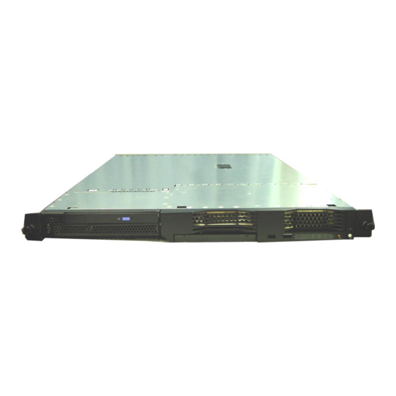
- Page 1 K1-1000 (MS-9245) 1U Rackmount Server English Version G52-S9245X4...
-
Page 2: Fcc-A Radio Frequency Interference Statement
Manual Rev: 3.0 Release Date: Sept. 2004 FCC-A Radio Frequency Interference Statement This equipment has been tested and found to comply with the limits for a class A digital device, pursuant to part 15 of the FCC rules. These limits are designed to provide reasonable protection against harmful interference when the equipment is operated in a commercial environment. -
Page 3: Copyright Notice
If a problem arises with your system and no solution can be obtained from the user’s manual, please contact your place of purchase or local distributor. Alternatively, please try the following help resources for further guidance. Visit the MSI website for FAQ, technical guide, BIOS updates, driver updates, and other information: faq/esc_faq_list.php Contact our technical staff at: http://www.msi.com.tw/program/service/faq/... -
Page 4: Safety Instructions
Safety Instructions Always read the safety instructions carefully. Keep this User’s Manual for future reference. Keep this equipment away from humidity. Lay this equipment on a reliable flat surface before setting it up. The openings on the enclosure are for air convection hence protects the equip- ment from overheating. -
Page 5: Table Of Contents
FCC-A Radio Frequency Interference Statement ... ii Copyright Notice ... iii Trademarks ... iii Revision History ... iii Technical Support ... iii Safety Instructions ... iv Chapter 1. Getting Started ... 1-1 System Specifications ... 1-2 Mainboard Layout ... 1-5 Packing Checklist ... - Page 6 Ultra320 SCSI Connector: SCSI 1 (Optional) ... 2-12 SO DIMM (Small Outline DIMM): J16 ... 2-13 Jumpers ... 2-14 Boot Block Jumper: JBBF1 ... 2-14 PCI-X 100/133 Jumper: JPCIXB1 ... 2-14 Clear CMOS Jumper: JBAT1 ... 2-14 Slots ... 2-15 PCI Slots ...
-
Page 7: Chapter 1. Getting Started
Chapter 1. Getting Started Getting Started Thanking you for choosing the MS-9245 1U Rackmount Server Barebone! The MS-9245 1U Rackmount Server is a high-performance barebone system powered by AMD Opteron 940. With high scalability, reliability, ease of use, and overall value, the MS-9245 makes an ideal choice for value conscious customers. -
Page 8: System Specifications
MS-9245 1U Rackmount Server System Specifications Mainboard MSI-9145 mainboard Supports AMD Opteron Chipset AMD 8111 I/O bridge AMD 8131 PCI-X Hub 2D/3D graphics controller ATI Rage XL Video Controller with 8MB of memory M e m o r y Supports up to 8 registered ECC DDR200/266/333/400 DIMMs... -
Page 9: Getting Started
1 IDE connector, supporting up to 2 ATA-100/133 compatible devices MSI Server Management IPMI 1.5 (optional) MSI-9549 BMC card (with QLogic Zircon UL BMC) and MSI iConsole AP support IPMI 1.5 (optional) 4 pcs, 40 x 28 mm system fan... - Page 10 MS-9245 1U Rackmount Server MS-9549 BMC Card Specification BMC Chip : Qlogic Zircon UL ( ARM7 TDMI 40M RISC) , 128pin PQFP Host hardware interface : LPC interface Host software interface : KCS interface Memory Size 256 X 16 Bits SRAM 4M Bits Flash Form Factor: Add-on Card on SO-DIMM (144 pin , Key position in 50)
-
Page 11: Mainboard Layout
Getting Started Mainboard Layout MS-9145 v3.X Mainboard... -
Page 12: Packing Checklist
MS-9245 1U Rackmount Server Unpack the package and check if all items listed below are present. If any item contained in the package is damaged or missing, please contact your local dealer for replacement. In addition, keep the box and packing materials for possible future use. Your MS-9245 1U Rackmount Server Barebone package should contain the following items: * MS-9245 1U Rackmount Server... -
Page 13: System Configuration
System Configuration This section shows the configuration of the MS-9245 from different angles, and the connectors and buttons on the front and back panel. Front View 1. Slim CD-ROM (optional) 2. Hot Swap SCSI (or S-ATA) HDD: HDD 1 (ID0) 3. -
Page 14: Rear View
MS-9245 1U Rackmount Server Rear View 1. AC Power Connector 2. Half Length PCI Slot 2 3. Full Length PCI Slot 1 4. Serial Port 5. VGA Port 6. (from left to right) USB Port 3 & USB Port 4 7. - Page 15 Table 1. MS-9245 Front Bezel & Rear I/O LEDs Definitions Color Power Green IDE HDD Activity Green Error Amber Location Blue (Controlled by MSI iConsole AP only) Information Amber Swappable SCSI Green HDD Access State Description System operating Blink System main power off and...
- Page 16 MS-9245 1U Rackmount Server Table 2. MS-9245 System Error and Diagnostic LEDs Definitions Item Error LED Diagnostic LED Diagnostic LEDs Diagnostic LEDs use signal display to help users understand their system. When POST or Service Processor detects an error, the corresponding LEDs light up to alert the user to the condition and help service personnel identify the failing component.
-
Page 17: Lan (Rj-45) Jacks: Giga-Bit Lan
The Rear Panel provides the following connectors: LAN (RJ-45) Jacks: Giga-bit LAN The mainboard provides two standard RJ-45 jacks for connection to Local Area Network (LAN). Giga-bit LAN enables data to be transferred at 1000, 100 or 10Mbps. You can connect a network cable to either LAN jack. USB Connectors The mainboard provides an UHCI (Universal Host Controller Interface) Univer- sal Serial Bus root for attaching USB devices such as keyboard, mouse or other USB-... -
Page 18: Serial Port Connectors: Com 1 & Com 2 (Optional)
MS-9245 1U Rackmount Server Serial Port Connectors: COM 1 & COM 2 (optional) The mainboard offers two 9-pin DIN connectors as serial ports COM 1 and COM 2. The ports are 16550A high speed communication ports that send/receive 16 bytes FIFOs. -
Page 19: Top View
Getting Started Top View 1. Proprietary Power Supply 2. Slim CD-ROM Drive 3. DIMM Slots 4. PCI Slots 5. Heatsinks 6. Fan Duct 7. AC Power Connector 1-13... -
Page 20: Chapter 2. Hardware Setup
Chapter 2. Hardware Setup Hardware Setup This chapter provides you with the information about hard- ware setup procedures. While doing the installation, be careful in holding the components and follow the installation procedures. For some components, if you install in the wrong orientation, the compo- nents will not work properly. -
Page 21: Central Processing Unit: Cpu
MS-9245 1U Rackmount Server Central Processing Unit: CPU The mainboard supports Single AMD processor(s). The mainboard uses two CPU sockets called Socket 940 for easy CPU installation. You can install SINGLE or DUAL CPUs on the mainboard to meet your own needs. -
Page 22: Cpu Installation Procedures For Socket 940
CPU Installation Procedures for Socket 940 1. Make sure that the computer is turned off, and the power cord disconnected before installing the CPU. 2. Pull the lever sideways away from the socket, and raise it up to a 90-degree angle. 3. -
Page 23: Memory
MS-9245 1U Rackmount Server The mainboard supports up to eight registered ECC DDR200/266/333/400 DIMMs providing up to 16GB of memory. Each DIMM slot supports up to a maximum size of 2GB. You can install either single- or double-sided modules to meet your own needs. DIMM Module Combination You can install either one or two DIMM modules on the slots. -
Page 24: Installing Ddr Modules
Installing DDR Modules The DDR DIMM has only one notch on the center of module. The module will only fit in the right orientation. Insert the DIMM memory module vertically into the DIMM slot. Then push it in until the golden finger on the memory module is deeply inserted in the socket. The plastic clip at each side of the DIMM slot will automatically close. -
Page 25: Power Supply
MS-9245 1U Rackmount Server The mainboard supports SSI power supply for the power system. Before inserting the power supply connector, always make sure that all components are installed properly to ensure that no damage will be caused. 18-Pin Main Power Supply Connector: J10 This connector provides power supply to the system board. -
Page 26: Hardware Setup
12V_1 12V_2 12V_3 RET1 12V_4 RET2 RET3 RET4 RET5 5V_1 RET6 5V_2 RET7 5V_3 RET8 5V_4 RET9 RET10 Molex_44472-1853 +5VSB +5VSB2 -ON_+OFF +5VSB_RET -EPOW +5VSB_RET2 -FAN_FAULT DCGOOD/-POR SPARE1 -FAN_HS SPARE2 Molex_43045-1413 Hardware Setup I2C_A0 I2C_A1 I2C_A2 I2C_CLK I2C_DATA I2C_INT PRES_DET# RESET GND1 GND2... -
Page 27: Connectors
MS-9245 1U Rackmount Server SM Card 3rd I2C Bus Connector: JSMB1 The mainboard provides one I2C (also known as I to connect to System Management Bus (SMBus) interface. JSMB1 Front Panel Connector: J13 The mainboard provides one front panel connector for electrical connection to the front panel switches and LEDs. -
Page 28: Hard Disk Connector: Ide1
Hard Disk Connector: IDE The mainboard has a 32-bit Enhanced PCI IDE and Ultra DMA 33/66/100/133 controller that provides PIO mode 0~4, Bus Master, and Ultra DMA 33/66/100/133 function. You can connect up to two hard disk drives, CD-ROM, 120MB Floppy (reserved for future BIOS) and other devices. -
Page 29: Fan Power Connectors: Sfan1/Sfan2/Sfan3/Sfan4/Sfan5
MS-9245 1U Rackmount Server Fan Power Connectors: SFAN1/SFAN2/SFAN3/SFAN4/SFAN5 The SFAN1/SFAN2/SFAN3/SFAN4/SFAN5 (system fans) support system cool- ing fan with +12V. It supports three-pin head connector. When connecting the wire to the connectors, always take note that the red wire is the positive and should be connected to the +12V, the black wire is Ground and should be connected to GND. -
Page 30: Rear Status Led: J20
Image Sil3512 single-chip PCI to 2-port Serial ATA host controller. JSA_11 JSA_22 Optional Serial ATA cable MSI Reminds You... Please do not fold the Serial ATA cable into 90-degree angle. Otherwise, the loss of data may occur during transmission. Hardware Setup... -
Page 31: Ultra320 Scsi Connector: Scsi 1 (Optional)
MS-9245 1U Rackmount Server Ultra320 SCSI Connector: SCSI 1 (Optional) SCSI (Small Computer System Interface) is a hardware interface that allows for connection of up to 15 peripheral devices. The mainboard provides one SCSI channel (SCSI 1) for you to connect SCSI devices such as SCSI hard disks. SCSI 1 2-12 68-Pin Ultra320 SCSI Connector... -
Page 32: So Dimm (Small Outline Dimm): J16
SO DIMM (Small Outline DIMM): J16 The SO DIMM has 144 pins and supports a full 64-bit transfer. It is specifically designed for users to install MSI’s proprietary server management tool -- MSI BMC (Baseboard Management Controller) card. Hardware Setup... -
Page 33: Jumpers
MS-9245 1U Rackmount Server Boot Block Jumper: JBBF1 Users can short connect pin#2-3 to recover the system BIOS with a Recovery Floppy. When the system is done with the job, the buzzer will beep to notify the user and set the jumper to its normal state (pin#1-2 short connected). JBBF1 PCI-X 100/133 Jumper: JPCIXB1 The jumper is used to set the channel B of 64-bit PCI bus (PCIX) to run at... -
Page 34: Slots
The motherboard provides two 64-bit PCI-X 100/133MHz slots. One is full length and the other is half length. PCI Slots Two PCI slots allow you to insert the expansion cards to meet your needs. When adding or removing expansion cards, make sure that you unplug the power supply first. -
Page 35: Chapter 3. Bios Setup
SETUP. You want to change the default settings for customized features. MSI Reminds You... 1. The items under each BIOS category described in this chapter are under continuous update for better system performance. -
Page 36: Entering Setup
MS-9245 1U Rackmount Server Power on the computer and the system will start POST (Power On Self Test) process. When the message below appears on the screen, press <F2> key to enter Setup. Press F2 to enter SETUP If the message disappears before you respond and you still wish to enter Setup, restart the system by turning it OFF and On or pressing the RESET button. -
Page 37: Getting Help
Getting Help After entering the Setup menu, the first menu you will see is the Main Menu. Main Menu The main menu lists the setup functions you can make changes to. You can use the arrow keys ( to select the item. The on-line description of the highlighted setup function is displayed at the bottom of the screen. -
Page 38: The Menu Bar
MS-9245 1U Rackmount Server Once you enter PhoenixBIOS Setup Utility, the Main Menu will appear on the screen. On the Main Menu screen, you will see basic BIOS settings including system time & date, and the setup categories the BIOS supplies. Use Arrow keys to move among the items and menus, and make changes to the settings. - Page 39 BIOS Setup Power Menu Use this menu to specify your settings for power management. Boot Menu Use this menu to specify the priority of boot devices. Exit Menu This menu allows you to load the BIOS default values or factory default settings into the BIOS and exit the BIOS setup utility with or without changes.
-
Page 40: The Main Menu
MS-9245 1U Rackmount Server The items inside the Main menu are for basic system information and configuration. Each item includes none, one or more setup items. Use the Up/Down arrow keys or <Tab> to highlight the item or field you want to modify and use the <+> or <->... - Page 41 items. Enter the information directly from the keyboard. This information should be provided in the documentation from your hard disk vendor or the system manufacturer. Type Multi-Sector Transfers LBA Mode Control 32-Bit I/O Tranfer Mode Ultra DMA Mode Large Disk Access Mode Select DOS if you have DOS.
-
Page 42: The Advanced Menu
MS-9245 1U Rackmount Server Items in the menu are divided into 7 sub-menus. Each sub-menu provides more settings. To enter the sub-menu, highligh the sub-menu you want to configure and press <Enter>. M a i n M a i n Advanced Advanced M a i n... -
Page 43: Bios Setup
Chipset Configuration The sub-menu is used to configure chipset features for optimal system performance. Advanced Advanced Advanced Advanced Advanced Chipset Configuration Chipset Configuration Chipset Configuration Chipset Configuration Chipset Configuration Setup Warning Setup Warning Setup Warning Setup Warning Setup Warning Setting items on this menu to incorrect values may cause Setting items on this menu to incorrect values may cause Setting items on this menu to incorrect values may cause Setting items on this menu to incorrect values may cause... - Page 44 MS-9245 1U Rackmount Server Dram ECC If all memory in the system supports ECC, enabling this will initial scrub dram and enable system requests to dram to be checked and/or corrected. Options: [Enabled], [Disabled]. ECC Scrub Redirection Enable Scrubber to correct errors detected in Dram during normal CPU requests (Foreground scrubbing).
- Page 45 NumLock [On] or [Off] turns NumLock on or off at boot up. [Auto] turns NumLock on if it finds a numeric key pad. Options: [On], [Off], [Auto]. Keyboard auto-repeat rate It sets the number of times a second to repeat a keystroke when you hold the key down.
- Page 46 MS-9245 1U Rackmount Server Interrupt It specifies the interrupt for Port A/Port B. Options: [IRQ 3], [IRQ 4]. PCI Configuration Press PgUp/<+> or PgDn/<-> to PCI Configuration. The following submenu will appear. Advanced Advanced Advanced Advanced Advanced PCI Configuration PCI Configuration PCI Configuration PCI Configuration PCI Configuration...
- Page 47 Enable Master Use this feature to enable selected device as a PCI bus master. Latency Timer Use this feature to minimize guaranteed time slice allotted for bus master in units of PCI bus clocks. Onboard SCSI Device/Onboard SATA Device (Optional) The sub-menu is used to configure the onboard SCSI or SATA device and will show either as Onboard SCSI Device or as Onboard SATA Device depend- ing on the hardware interface integrated onboard.
- Page 48 MS-9245 1U Rackmount Server Com Port Address This feature allows you to enable/disable the Com port on the motherboard. Options: [Disabled], [On-board COM A]. Console connection This feature indicates whether the console is connected directly to the system or a modem is used for connection. Options: [Direct], [Via modem]. Baud Rate It allows you to select delay befor key repeat.
- Page 49 View DMI event log Press Enter to view the contents of the DMI event log. Clear all DMI event logs Setting this to Yes will clear the DMI event log after rebooting. Options: [Yes], [No]. Event Logging Select [Enabled] to allow logging of DMI events. Options: [Enabled], [Disabled]. IPMI Press PgUp/<+>...
- Page 50 MS-9245 1U Rackmount Server Change COM port Setting Select this line to change COM port setting. Options: [Yes], [No]. COM port on BMC Select this line to enable/disable COM port on BMC. Options: [Disabled], [IPMI], [CLI]. Clear System Event Log Enabling this selection will force the BIOS to clear the System Event Log on the next boot.
-
Page 51: The Security Menu
The Security Menu This section lets you set security passwords to control access to the system at boot time and/or when entering the BIOS setup program. It also allows you to set virus protection at hard disk boot sector. M a i n M a i n A d v a n c e d A d v a n c e d... - Page 52 MS-9245 1U Rackmount Server Password on boot Choosing Enabled requires a password on boot. It requires prior setting of the Super- visor password. If supervisor password is set and this option is disabled, BIOS assumes user is booting. Options: [Enabled], [Disabled]. Fixed disk boot sector Write protects the boot sector on the hard disk for virus protection.
-
Page 53: The Power Menu
Use this menu to specify your settings for Power Management. Remember that the options available depend upon the hardware installed in your system. M a i n M a i n A d v a n c e d A d v a n c e d M a i n A d v a n c e d M a i n... - Page 54 MS-9245 1U Rackmount Server Resume On Modem Ring Select On to wake up system when an incoming call is detected on the modem. Options: [On], [Off]. Resume On LAN Select On to wake up system by LAN devices. Options: [On], [Off]. Resume On Time Select On to wake up system at predetermined time.
-
Page 55: The Boot Menu
Use this menu to arrange to specify the priority of the devices from which the BIOS will attempt to boot the Operating System. M a i n M a i n A d v a n c e d A d v a n c e d M a i n A d v a n c e d M a i n... -
Page 56: The Exit Menu
MS-9245 1U Rackmount Server The following sections describe each of the options on this menu. Note that <Esc> does not exit this menu. You must select one of the items from the menu or menu bar to exit. M a i n M a i n A d v a n c e d A d v a n c e d... -
Page 57: Chapter 4. Chassis Installation
Chapter 4. Chassis In- stallation Chassis Installation This chapter provides instructions on the hardware installation of the MS-9245 in two sections. System Assembly illustrates how to assemble each component of the MS-9245. Rack Mounting de- scribes the procedures for mounting the unit into the rack in details. You can use the system assembly flowchart and the chart below to determine the proper sequence for removing or installing compo- nents to the server. -
Page 58: System Assembly
MS-9245 1U Rackmount Server Chassis Cover 1. Locate the release button on the chas- sis cover. 2. Lift the release button to the upright pos ition. Pus h the c has s is c over f orward. 3. Lift the chassis cover to remove it from the system. -
Page 59: Cpu And Heatsink
CPU and Heatsink 1. Locate the First and Second CPU sockets. 2nd CPU Socket 1st CPU Socket 3. Place the CPU on top of the socket with the cut edge pointing to the ar- row sign. cut edge 4. Push the lever down to secure the CPU in place. -
Page 60: Cpu And Heatsink (Continued)
MS-9245 1U Rackmount Server CPU and Heatsink (continued) 5. Unscrew the heatsink as indicated below with blue circles. 6. The heatsink paste helps to enhance heat dissipation of the CPU. Before installing the heatsink, make sure that you remove the plastic cover to uncover the heatsink paste under the heatsink. -
Page 61: Dimm
DIMM Locate the DIMM slots. Install at least two DDR modules on the slots. The plastic clip at each side of the DIMM slot will automati-cally close. NOTE Memory modules “in pairs” must be of the same type and size. Please refer to DIMM Module Combination on page2-4 for more information. -
Page 62: Pci Cards
MS-9245 1U Rackmount Server PCI Cards PCI Slot 2 Remove the clip from the chassis. ety lock afety lock PCI Slot 1 Take out the I/O shield on the first PCI slot. Insert the add-on card to the PCI slot. - Page 63 Chassis Installation Replace the clip. Follow the procedures described earlier to install the second PCI Card.
-
Page 64: Serial Ata/Scsi Hard Disk Drives (Optional)
MS-9245 1U Rackmount Server Serial ATA/SCSI Hard Disk Drives (Optional) Unlock the HDD device holder and pull it out from the chassis. Screw the hard disk to the HDD device holder. - Page 65 Chassis Installation Slide the HDD device holder into the chas- sis and push it backward until you hear a “click” sound to secure the holder. USB tray You may pull the USB tray open to rest any USB device on it.
-
Page 66: Rack Mounting
MS-9245 1U Rackmount Server Rack Mounting Take out the rail set for rack mounting. rail set Position the rail to the rack cabin. Rear Right Press the button to push the locking tab forward. The rail will secure itself to the cabin. - Page 67 Chassis Installation Position the rail to the rack cabin. Front Right Press the button to push the locking tab forward. The rail will secure itself to the cabin. Screw to secure the rail on the front. 4-11...
- Page 68 MS-9245 1U Rackmount Server Follow the same procedures as men- tioned earlier in this section to screw the left rail on the front and rear. Align the 1U rackmount server to the rails and push it backward until it reaches the end.