Table of Contents
Advertisement
Quick Links
Advertisement
Table of Contents

Related Manuals for MSI MS-9221


Summary of Contents for MSI MS-9221
- Page 1 MS-9221 1U Rackmount Server English Version G52-S9221X1...
-
Page 2: Copyright Notice
If a problem arises with your system and no solution can be obtained from the user’s manual, please contact your place of purchase or local distributor. Alternatively, please try the following help resources for further guidance. Visit the MSI website for FAQ, technical guide, BIOS updates, driver updates, and other information: faq/esc_faq_list.php Contact our technical staff at: support@msi.com.tw... -
Page 3: Safety Instructions
Safety Instructions Always read the safety instructions carefully. Keep this User’s Manual for future reference. Keep this equipment away from humidity. Lay this equipment on a reliable flat surface before setting it up. The openings on the enclosure are for air convection hence protects the equip- ment from overheating. -
Page 4: Fcc-A Radio Frequency Interference Statement
VOIR LA NOTICE D’INSTALLATION AVANT DE RACCORDER AU RESEAU. Micro-Star International MS-9221 This device complies with Part 15 of the FCC Rules. Operation is subject to the following two conditions: (1) this device may not cause harmful interference, and (2) this device must accept any interference received, including interference that may cause undesired operation. -
Page 5: Weee (Waste Electrical And Electronic Equipment) Statement
WEEE (Waste Electrical and Electronic Equipment) Statement... -
Page 8: Table Of Contents
Rear View ... 1-7 Rear Bezel ... 1-7 System Specifications ... 1-9 Mainboard Layout ... 1-12 MSI Special Features ... 1-13 PC Alert™ III ... 1-13 Chapter 2. System Hardware ... 2-1 System Assembly Flowchart ... 2-2 System Assembly ... 2-4 Removing the Chassis Cover ... - Page 9 Installing DDR-II Modules ... 3-7 Power Supply ... 3-8 SSI 24-Pin Power Connector: JPWR1 ... 3-8 SSI 8-Pin Power Connector: JPWR2 ... 3-8 Back Panel ... 3-9 Connectors ... 3-10 Floppy Disk Drive Connector: JFDD ... 3-10 Chassis Intrusion Switch Connector: JCI1 ... 3-10 Fan Power Connectors: CPUFAN1/2/3, POW ERFAN1/2/3/4 ...
- Page 10 Appendix A: SCSI BIOS Setup (Optional) ... A-1 Entering SCSI BIOS ... A-2 Control Keys ... A-2 Selecting the SCSI Channel ... A-2 Selecting the Management Type ... A-2 Configure/View SCSI Controller Settings ... A-4 SCSI Bus Interface Definitions ... A-4 Additional Options ...
-
Page 11: Chapter 1. Getting Started
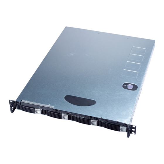
The MS-9221 1U Rackmount Server is a high-performance barebone system powered by dual Intel VS, and Hance Rapids chipsets. W ith high scalability, reliability, ease of use, and overall value, the MS-9221 makes an ideal choice for value conscious customers. Getting Started ®... -
Page 12: Packing Checklist
MS-9221 1U Rackmount Server Unpack the package and check if all items listed below are present. If any item contained in the package is damaged or missing, please contact your local dealer for replacement. In addition, keep the box and packing materials for possible future use. -
Page 13: Getting Started
Getting Started Chassis Rail Kit bracket x 2 bracket x 2 rail x 2 rail holder x 4 M 5x8 screw x 10 M 5x15 screw x 2 8”32x5 screw x 10 M 4x6 screw x 16 M 4x4 screw x 10 M4 nut x 8 washer x 10... -
Page 14: System Overview
MS-9221 1U Rackmount Server This section shows the configuration of the MS-9221 from different angles, and the connectors and buttons on the front and back panel. Top View System Overview HDD Tray Slim CD-ROM Drive (Optional) Slim Floppy Disk Drive... -
Page 15: Front View
Front View Front Bezel CD-ROM Drive Slim CD-ROM Drive (Optional) Floppy Disk Drive Slim Floppy Disk Drive HDD Bay Swappable Hard Disk Drive Bays Port USB Port HDD Power/Status LEDs HDD Activity LED This indicator shows the activity status of the hard disk drive. It flashes when the system is accessing data on the hard disk and remains off when no disk activity is detected. - Page 16 MS-9221 1U Rackmount Server Power LED This indicator shows the power status of the system. It glows when the main power is turned on. Status LEDs of LAN# 1/2 1. The green LED is on when there is an active connection on the LAN port.
-
Page 17: Rear View
Rear View Rear Bezel PS/2 Keyboard/Mouse Connector Serial Port LAN Jacks Rear Bezel LEDs Color RJ45 NIC 1 / NIC 2 Ac cess Yellow (Right Side) RJ45 NIC 1 / NIC 2 Orange Link Speed Green (Left Side) Getting Started USB Ports VGA Port State... - Page 18 MS-9221 1U Rackmount Server M ouse/Keyboard Connector Pin6 Keyboard Clock Mouse Clock Pin4 VCC Pin2 Mouse Data Keyboard Data Serial Port 1 2 3 4 5 6 7 8 9 SIGNAL SOUT USB Port SIGNAL -Data +Data Gigabit LAN Jack...
-
Page 19: System Specifications
† MS-9621 server board † Dual Intel ® Xeon™ processors (800 MHz FSB) in Socket 604 † 1MB/2MB L2 Cache † 6.4GB/s Trans Rate (For more information on compatible components, please visit http://www.msi. com.tw/program/products/server/svr/pro_svr_qvl.php) Chipset † Intel ® Lindenhurst-VS MCH (Memory Controller Hub) - Supports dual processors at 200 MHz (x4 transfers) - System bus bandwidth of 6.4 GB/s... - Page 20 MS-9221 1U Rackmount Server Onboard Peripherals † On-Board Peripherals include: - 1 floppy port supports 1 FDD with 1.44M and 2.88Mbytes - 2 serial ports (COM1 & COM2) - 1 VGA port - 4 USB 2.0 ports (Rear * 2/ Front * 2)
- Page 21 - Integrated TMDS transmitter with support for Digital Flat Panel (DFP) monitors - Onboard 8MB Video SDRAM MSI Reminds You... Please refer to Table 1 for 2D modes supporting both CRT and LCD. The table specifies the minimum memory requirements for various display resolutions, refresh rates and color depths.
-
Page 22: Mainboard Layout
MS-9221 1U Rackmount Server T: M ouse B: Keyboar d POW ERFAN1 Por ts BATT PCIX 1 PCIX 2 PCIE1 PCI 1 SCSI 1 E7320 Master2 Series (MS-9621 v1.X) CEB Server Board 1-12 Mainboard Layout J PWR1 CPUFAN1 DIM M 6... -
Page 23: Msi Special Features
MSI Special Features PC Alert™ III The PC Alert III is a utility you can find in the application CD. The utility is just like your PC doc- tor that can detect the following PC hardware status during real time operation: ö... -
Page 24: Chapter 2. System Hardware
System Hardware This chapter provides instructions on the hardware installation of the MS-9221 in two sections. System Assembly illustrates how to as- semble each component of the MS-9221. Rack Mounting describes the procedures for mounting the unit into the rack in details. You can... -
Page 25: System Assembly Flowchart
MS-9221 1U Rackmount Server System Assembly Flowchart The following flowchart shows basic system assembly procedures. Please note that always wear anti-static gloves when handling electrical components and exercise caution during the installation process. For more information, contact your local dealer or experienced technician. - Page 26 INSTALL PCI CARDS REPLACE RISER CARD BRACKET INSTALL HARD DISK DRIVES CONNECT HDD, FDD, CD-ROM CABLES & POWER CORDS CHECK IF ALL PARTS ARE PROPERLY CONNECTED REPLACE CHASSIS COVER FINISH System Hardware...
-
Page 27: System Assembly
MS-9221 1U Rackmount Server System Assembly Removing the Chassis Cover 1. Press the release buttons and slide the chassis cover forwards. 2. Lift up the cover and remove it from the chassis. NOTE: B e f o r e y o u r e m o v e o r in s t a ll an y components, make sure the server is not turned on or connected to the AC power. -
Page 28: Cpu, Heatsink, And Fan Duct
CPU, Heatsink, and Fan Duct 1. On top of the CPU is a fan duct designed to enhance heat dissipation of the CPU. Lift up & remove the fan duct before installing the CPU. 2. Locate the first CPU socket and raise the lever up to its full extent. CPU2 CPU1 3. - Page 29 MS-9221 1U Rackmount Server 5. Place the heat sink on top of CPU1 and secure the screws on both sides. Note: The heat sink has to be installed to prevent the CPU from overheating. 6. Follow the same procedures to install the second CPU and heat sink.
-
Page 30: Ddr Memory
DDR Memory 1 . L oc at e t h e D I M M s l ot s on t h e mainboard. Insert the DIMM memory module vertically into the DIMM slot. Then push it in until the golden finger on the memory module is deeply in- serted in the socket. -
Page 31: Memory Population Rules
MS-9221 1U Rackmount Server Memory Population Rules The mainboard supports both single- & dual-channel modes. Install at least one DIMM module on the slots. You can install either single- or double-sided modules to meet your own needs. In dual-channel mode, make sure that you install memory modules of the same type and density on DDR-II DIMMs. -
Page 32: Pci Expansion Card
System Hardware PCI Expansion Card 1. Locate the riser card bracket and lift it up from the chassis. 2. Unscrew the cover plates and put them aside for later use. 3. Insert the expansion card into an appropriate PCI slot on the riser card. - Page 33 MS-9221 1U Rackmount Server 4. Place the riser card bracket on top of the motherboard PCI slot. Align the riser card golden fingers with the PCI slot and fit the riser card bracket into the bracket holder on the chassis (as indicated by circles).
-
Page 34: Hard Disk Drive
Hard Disk Drive 1. To release the hot-swapping HDD tray, flip open the tray lever and pull the tray out of the bay. 2. At the rear of the HDD are four screw holes, two on the right and two on the left side. - Page 35 MS-9221 1U Rackmount Server 3. Insert the HDD tray into the bay and push the tray lever back in place. NOTES 2-12...
-
Page 36: Rack Mounting
1. Pull the inner channel out. latch Press the latch to disconnect. 2. Assemble the inner rail to the chassis. Fasten 6 screws at least to attach the inner channel onto the chassis. Rack Mounting M4 screw System Hardware 2-13... - Page 37 MS-9221 1U Rackmount Server 3. Mount the L-shaped bracket onto the outer channel. FRONT 4. Mount the slides to the vertical racks. Type A M4 screw 2-14 BACK U se b l a ck rou n d head screws. shall be in flush position...
- Page 38 System Hardware 5. Insert the chassis into the frame. NOTES 2-15...
-
Page 39: Chapter 3. Mainboard Hardware
Chapter 3. Mainboard Hardware Mainboard Hardware This chapter provides you with the information about hardware setup procedures. W hile doing the installation, be careful in holding the c omponents and follow the installation procedures . For s ome components, if you install in the wrong orientation, the components will not work properly. -
Page 40: Quick Components Guide
MS-9221 1U Rackmount Server Quick Components Guide POWERFAN1, p.3-10 JPWR1, p.3-8 Back Panel I/O, p.3-9 PCI-X Slot, p.3-18 JCI1, p.3-10 JBAT, p.3-17 SCSI1, p.3-14 CPUFAN1, p.3-10 DIMM6~1, p.3-6 JFDD, p.3-10 IDE2/1, p.3-11 COM2, p.3-13 J11, p.3-14 CN11, p.3-16 CPU, p.3-3 JPWR2, p.3-8... -
Page 41: Central Processing Unit: Cpu
1. If SINGLE CPU is intended, always install the CPU on the CPU1 socket. 2. To install DUAL CPUs on the board, you must use the same type of CPUs running at the same FSB frequency. For more information on compatible components, please visit http://www.msi.com. tw/program/products/server/svr/pro_svr_qvl.php . MSI Reminds You... -
Page 42: Cpu Installation Procedures For Socket 604
MS-9221 1U Rackmount Server CPU Installation Procedures for Socket 604 1. Please turn off the power and unplug the power cord before installing the CPU. 2. Pull the lever s ideways away from the socket. Make sure to raise the lever up to a 170-de- gree angle. -
Page 43: Installing The Intel Cpu Cooler
Installing the Intel CPU Cooler 1. Flip over the mainboard and locate the position of the CPU sockets. 2. Stick the backplates to the back of the CPU sockets with holes aligned. CPU cooler backplates 3. Install the CPU(s) following the in- structions on page 3-4. -
Page 44: Memory
The mainboard provides 6 slots for 240-pin DDR-II DIMM (Double In-Line Memory Module) modules. You can install DDR-II 400 SDRAM modules on the DDR-II DIMM slots (DIMM 1~6). For more information on compatible components, please visit http://www.msi.com. tw/program/products/server/svr/pro_svr_qvl.php . Memory Bus Features... -
Page 45: Memory Population Rules
2. Insert the DIMM memory module vertically into the DIMM slot. Then push it in until the golden finger on the memory module is deeply inserted in the socket. MSI Reminds You... You can barely see the golden finger if the module is properly inserted in the socket. -
Page 46: Power Supply
MS-9221 1U Rackmount Server Before inserting the power supply connector, always make sure that all components are installed properly to ensure that no damage will be caused. SSI 24-Pin Power Connector: JPWR1 This connector allows you to connect to an SSI power supply. To connect to the SSI power supply, make sure the plug of the power supply is inserted in the proper orientation and the pins are aligned. -
Page 47: Back Panel
M o us e Keyboard COM 1 M ouse/Keyboard Connector Pin5 Mouse/KBD Clock Pin6 NC Pin4 VCC Pin1 Pin2 NC Mouse/KBD DATA Serial Port 1 2 3 4 5 6 7 8 9 VGA Port Back Panel USB Ports Pin3 GND SIGNAL RJ-45 LAN Jack Link Indicator... -
Page 48: Connectors
MS-9221 1U Rackmount Server The mainboard provides connectors to connect to FDD, IDE HDD, case, LAN, USB Ports, CPU/system power supply fans, ... and etc. Floppy Disk Drive Connector: JFDD The mainboard provides a standard floppy disk drive connector that supports 1.44M and 2.88M floppy disk types. -
Page 49: Front Usb Connector: Jusb1
USB HDD, digital cameras, M P3 players, printers, mo- dems and the like. JUSB1 MSI Reminds You... Note that the pins of VCC and GND must be connected correctly to avoid possible damage. ATA100 Hard Disk Connectors: IDE1 & IDE2 The mainboard has a 32-bit Enhanced PCI IDE and Ultra ATA66/100 controller that provides PIO mode 0~4, Bus Master, and Ultra ATA66/100 function. -
Page 50: Serial Ata Raid 0, 1 Connectors: Sata1, Sata2
MS-9221 1U Rackmount Server Serial ATA RAID 0, 1 Connectors: SATA1, SATA2 ® The southbridge Intel Hance Rapids ICH provides a hybrid solution that combines two independent SATA ports for support of up to two Serial ATA (Serial ATA RAID) drives and utilizes Adaptec Embedded Serial ATA RAID Software to support RAID levels 0 and 1 for easy management of the storage subsystems. -
Page 51: Serial Port Connector: Com 2
Serial Port Connector: COM 2 The mainboard provides one 9-pin header as serial port COM 2. The port is a 16550A high speed communication port that sends/receives 16 bytes FIFOs. You can attach a serial mouse or other serial devices directly to it. COM 2 Front Panel Connector: JFP1 The mainboard provides one front panel connector for electrical connection to the... -
Page 52: Ultra320 Scsi Connectors: Scsi1 (Optional)
MS-9221 1U Rackmount Server Ultra320 SCSI Connectors: SCSI1 (Optional) SCSI (Small Computer System Interface) is a parallel interface standard for attaching peripheral devices to computers. Ultra320 SCSI is the seventh generation of SCSI I/O technology, and has a maximum data rate speed of 320 MB/sec. SCSI’s commitment... -
Page 53: Lan Led Connectors: J5 & J7
LAN LED Connectors: J5 & J7 The LAN LED connectors are used to connect LAN LEDs, which show the activity of the LAN. The J5 is for JLAN 1 jack and the J7 is for JLAN2 jack. Both JLAN 1 & JLAN2 jacks are located on the back panel. -
Page 54: Parallel Port Header: Cn11
MS-9221 1U Rackmount Server Parallel Port Header: CN11 The mainboard provides a 25-pin header for connection to an optional parallel port bracket. The parallel port is a standard printer port that supports Enhanced Parallel Port (EPP) and Extended Capabilities Parallel Port (ECP) mode. -
Page 55: Jumper
The motherboard provides the following jumpers for you to set the computer’s function. This section will explain how to change your motherboard’s function through the use of jumpers. Clear CMOS Jumper: JBAT There is a CMOS RAM onboard that has a power supply from external battery to keep the data of system configuration. -
Page 56: Slot
MS-9221 1U Rackmount Server PCI (Peripheral Component Interconnect) Slot The motherboard provides one 64-bit PCI-X slot. MSI Reminds You... When adding or removing expansion cards, make sure that you unplug the power supply first. Meanwhile, read the documentation for the ex-... -
Page 57: Chapter 4. Bios Setup
SETUP. ² You want to change the default settings for customized features. MSI Reminds You... 1. The items under each BIOS category described in this chapter are under continuous update for better system performance. -
Page 58: Entering Setup
MS-9221 1U Rackmount Server Power on the computer and the system will start POST (Power On Self Test) process. W hen the message below appears on the screen, press <F2> key to enter Setup. Press F2 to enter SETUP If the message disappears before you respond and you still wish to enter Setup, restart the system by turning it OFF and On or pressing the RESET button. -
Page 59: Getting Help
Getting Help After entering the Setup menu, the first menu you will see is the Main Menu. M ain M enu The main menu lists the setup functions you can make changes to. You can use the arrow keys ( to select the item. -
Page 60: The Menu Bar
MS-9221 1U Rackmount Server Once you enter PhoenixBIOS Setup Utility, the Main Menu will appear on the screen. On the Main Menu screen, you will see basic BIOS settings including system time & date, and the setup categories the BIOS supplies. Use Arrow keys to move among the items and menus, and make changes to the settings. - Page 61 BIOS Setup Boot Use this menu to specify the priority of boot devices. PC Health This entry shows your PC health status. Exit This menu allows you to load the BIOS default values or factory default settings into the BIOS and exit the BIOS setup utility with or without changes.
-
Page 62: Main
MS-9221 1U Rackmount Server The items inside the Main menu are for basic system information and configuration. Each item includes none, one or more setup items. Use the Up/Down arrow keys or <Tab> to highlight the item or field you want to modify and use the <+> or <-> key to switch to the value you prefer. - Page 63 provided in the documentation from your hard disk vendor or the system manufacturer. [Type] [Multi-Sector Transfers] [LBA Mode Control] [32-Bit I/O] [Tranfer Mode] [Ultra DMA Mode] Boot Features The sub-menu is used to configure system boot-up features. Floppy Check: Summary Screen: Boot-time Diagnostic Screen: QuickBoot Mode: Chassis Intruder Detect:...
- Page 64 MS-9221 1U Rackmount Server the warning message, set the field to [Reset]. The setting of the field will automatically return to [Enabled] later. Settings: [Enabled], [Reset], [Disabled]. Sy stem M emory It displays amount of conventional memory detected during boot up.
-
Page 65: Advanced
Items in the menu are divided into several sub-menus. Each sub-menu provides more settings. To enter the sub-menu, highligh the sub-menu you want to configure and press <Enter>. Main Advanced Large Disk Access Mode: Paralle ATA: Serial ATA: Native Mode Operation: SATA RAID Enable: 8Advanced Chipset Control 8Advanced Processor Options... - Page 66 MS-9221 1U Rackmount Server available IRQs to use for HDD. * New OS that supports switch to Native Mode (WinXP, Windows .NET Server) can set SATA and PATA to Native Mode. * Maximum 6 ATA devices to connect (4 for P-ATA & 2 for S-ATA).
- Page 67 Onboard SCSI 7901 (Optional) This setting controls the onboard SCSI 7901 controller. Setting options: [Enabled], [Disabled]. MSI Reminds You... SATA systems DO NOT support this function. PCI Device Option ROM Configuration Press PgUp/<+> or PgDn/<-> for PCI Configuration. The following submenu will appear.
- Page 68 Console Connection: Continue C.R. after POST : Com Port Address This feature allows you to enable/disable the Com port on the motherboard. Options: [Disabled], [On-board COM A]. Baud Rate It allows you to select delay befor key repeat. Options: [300], [1200], [2400], [9600], [19.2K], [38.4K], [57.6K], [115.2K].
- Page 69 BIOS Setup Flow Control This feature allows you to enable flow control. Options: [None], [XON/XOFF], [CTS/RTS]. Console Connection This feature indicates whether the console is connected directly to the system or a modem is used for connection. Options: [Direct], [Via modem]. Continue C.
-
Page 70: Security
MS-9221 1U Rackmount Server This section lets you set security passwords to control access to the system at boot time and/or when entering the BIOS setup program. It also allows you to set virus protection at hard disk boot sector. - Page 71 BIOS Setup Password on boot Choosing [Enabled] requires a password on boot. It requires prior setting of the supervisor password. If the supervisor password is set and this option is disabled, BIOS assumes the user is booting. Options: [Enabled], [Disabled]. 4-15...
-
Page 72: Power
MS-9221 1U Rackmount Server Use this menu to specify your settings for Power Management. Remember that the options available depend upon the hardware installed in your system. Main Advanced PCIE LAN (PCIE PME) Wake Up: Onboard 5705 LAN Wake Up (PCI32 PME):... - Page 73 Resume Date The date format is <MM> <DD> <YYYY>. Resume T ime The time format is <HH> <MM> <SS>. After Power Failure This setting specifies whether your system will reboot after a power failure or interrupt occurs. Available settings are: [Stay Off] Returns the system to an off state.
-
Page 74: Boot
MS-9221 1U Rackmount Server Use this menu to arrange and specify the priority of the devices from which the BIOS will attempt to boot the Operating System. Main Advanced +Removable Devices +Hard Drive CD-ROM Drive Network Boot MBA v6.2.11 Slot 0430 MBA v7.5.6 Slot 0200... -
Page 75: Pc Health
Spread Spectrum W hen the motherboard’s clock generator pulses, the extreme values (spikes) of the pulses creates EMI (Electromagnetic Interference). The Spread Spectrum function reduces the EMI generated by modulating the pulses so that the spikes of the pulses are reduced to flatter curves. - Page 76 MS-9221 1U Rackmount Server 2. The greater the Spread Spectrum value is, the greater the EMI is reduced, and the system will become less stable. For the most suit- able Spread Spectrum value, please consult your local EMI regulation. 3. Remember to disable Spread Spectrum if you are overclocking be- cause even a slight jitter can introduce a temporary boost in clock speed which may just cause your overclocked processor to lock up.
-
Page 77: Exit
The following sections describe each of the options on this menu. Note that <Esc> does not exit this menu. You must select one of the items from the menu or menu bar to exit. Main Advanced Exit Saving Changes Exit Discarding Changes Load Setup Defaults Discard Changes Save Changes... -
Page 78: Appendix A: Scsi Bios Setup (Optional
Appendix A: SCSI BIOS Setup This chapter provides information on the Small Computer System Interface (SCSI) BIOS setup utility and allows you to configure the SCSI subsystem for optimum use. You may need to run the SCSI BIOS setup utility when: ²... -
Page 79: Entering Scsi Bios
MS-9221 1U Rackmount Server Power on the computer and the system will start POST (Power On Self Test) process. W hen the message below appears on the screen, press <Ctrl> + <A> keys simulta- neously to enter SCSI BIOS utility. - Page 80 Would you like to configure the SCSI controller, or run the SCSI Disk Utilities? Select the option and press <Enter>. Configure/View SCSI Controller Settings Configure/View SCSI Controller Settings Use this option for SCSI controller configurations. SCSI Disk Utilities Use this option to manage the attached SCSI device. AIC-7901 at slot 07, 03:07:00 Options SCSI Disk Utilities...
-
Page 81: Configure/View Scsi Controller Settings
MS-9221 1U Rackmount Server Configure/View SCSI Controller Settings There are 8 items in the “Configure/View SCSI Controller Settings” screen. These items display or allow you to change the SCSI controller’s settings. Use the arrow keys to highlight the item and then press <Enter> to select the value you want in each item or enter each item’s sub-menu screen. -
Page 82: Additional Options
Boot Device Configuration Press <Enter> to enter the sub-menu screen. Boot Device Configuration Single Image Master SCSI Controller ... AIC-7901 at slot 07 03:07:00 Select SCSI peripheral from which to boot Boot SCSI Controller ... AIC-7901 at slot 07 03:07:00 Boot SCSI ID ... - Page 83 MS-9221 1U Rackmount Server SCSI Device ID Sync Transfer Rate (MB/Sec) ... 320 320 320 320 320 320 320 320 Packetized... Yes Yes Yes Yes Yes Yes Yes Yes QAS... Yes Yes Yes Yes Yes Yes Yes Yes Initiate Wide Negotiation ... Yes Yes Yes Yes Yes Yes Yes Yes Enable Disconnection ...
- Page 84 Send Start Unit Command W hen set to Yes, the SCSI controller sends the Start Unit command to the specified SCSI device during bootup. The interface powers up the SCSI device on-at-a-time during bootup, reducing the load on the computer’s power supply. Setting options: [Yes], [No].
-
Page 85: Bios Information
MS-9221 1U Rackmount Server POST Display Mode The field determines how much information about your SCSI controller and devices appear on the screen during bootup. For the most complete information, choose [Diagnostic]. For a faster boot, select [Silent]. Setting options: [Verbose], [Silent], [Diagnostic]. -
Page 86: Disk Utilities
Select SCSI Disk and press <Enter> SCSI ID#0: SCSI ID#1: SCSI ID#2: SCSI ID#3: SCSI ID#4: SCSI ID#5: SCSI ID#6: SCSI ID#7: SCSI ID#8: SCSI ID#9: SCSI ID#10: SCSI ID#11: SCSI ID#12: SCSI ID#13: SCSI ID#14: SCSI ID#15: Select the SCSI device which you want to manage by highlighting the item and press <Enter>. -
Page 87: Appendix B: Adaptec Sata Raid Utility For Intel Ich-Hr (Optional
1. Supports 150 MB/s transfers with CRC error checking 2. Data handling optimizations including tagged command queuing, elevator seek and packet chain command MSI Reminds You... All the information/volumes listed in your system might differ from the illustrations in this appendix. -
Page 88: Introduction
MS-9221 1U Rackmount Server 1. Overview Adaptec Embedded Serial ATA RAID with HostRAID the Serial ATA I/O controller by supporting RAID levels 0 and 1. HostRAID adds entry level RAID support to the Serial ATA I/O controller. W ith HostRAID, you can add reliable performance and full data protection. - Page 89 Adaptec SATA RAID Utility for Intel ICH-HR Adaptec RAID Configuration (ARC) Utility—Part of the controller’s built-in BIOS code. You start ARC by pressing Ctrl+A during BIOS startup. For details, see Adaptec RAID Configuration Utility. Array Configuration Utility (ACU)—A DOS/BIOS application used to create, configure, and manage arrays.
-
Page 90: Installing The Driver
MS-9221 1U Rackmount Server This section describes installing the driver and setting up the new array for the drives attached to your controller. Before you get started, you need to select from the following scenarios for installing the controller driver on W indows or Linux systems:... -
Page 91: Installing The Driver In An Existing Windows System
2. Installing the Driver in an Existing Windows System In this scenario, you are installing a driver in a system that already has a W in- dows operating system. To install the driver: 1. Create a driver disk by following the instructions from the Web site or the product CD. -
Page 92: Installing Suse Linux
MS-9221 1U Rackmount Server 4. Installing SuSE Linux Installing the Driver in a New Linux System In this scenario, you are installing the driver in a new Linux system. To install the driver: 1. Obtain a driver disk from either the Web site or the product CD. -
Page 93: Installing Adaptec Storage Manager - Browser Edition
Typical installation. Compact — Installs only the components required on a remotely managed system. See Managed System Components, above. MSI Reminds You... When you perform a Typical or Compact installation, components needed for communication and remote management are installed automatically. -
Page 94: Installing Adaptec Storage Manager On Windows
MS-9221 1U Rackmount Server 4. Installing Adaptec Storage Manager on Windows MSI Reminds You... When installing on a FAT 32 file system, the folder being installed is automatically hidden. To install Adaptec Storage Manager – Browser Edition: 1. Verify that a supported browser is installed. See Supported Browsers for details. -
Page 95: Configuring Internet Browsers On Windows
Active Scripting Allow per session cookies (not stored) MSI Reminds You... In Internet Explorer 6.0 there is no security setting for cookies. Cookie configuration was removed from the Privacy tab. There is no setting for blocking Intranet cookies. - Page 96 MS-9221 1U Rackmount Server Configuring Netscape Navigator for Local Management MSI Reminds You... These instructions apply specifically to version 7 and may differ in later versions. To configure Netscape Navigator: 1. Log in to your computer with administrator access. 2. Select Edit > Preferences.
-
Page 97: Installing Adaptec Storage Manager On Linux
5. Installing Adaptec Storage Manager on Linux MSI Reminds You... When performing this ins tallation, keep in mind that Linux is case sensitive. To install Adaptec Storage Manager on a Linux computer and configure the de- sired Internet browser: 1. Insert the product installation CD. -
Page 98: Using Adaptec Storage Manager - Browser Edition
MS-9221 1U Rackmount Server Using Adaptec Storage Manager – Browser Edition 1. Overview This section describes how to use Adaptec Storage Manager – Browser Edition to manage arrays. Once you are logged in, you will find convenient online help to guide you through the details of creating, configuring, and managing arrays. -
Page 99: Architecture Overview
2. Architecture Overview A locally managed system requires all of these components: A supported Web browser, which should already be installed on the system. The Adaptec Web service which supplies content displayed on the Web brows er. An Adaptec-supplied storage agent. A remotely managed system requires all of these components: The remote system must contain a browser. -
Page 100: Installing A Security Certificate
MS-9221 1U Rackmount Server Notes: W hen running Adaptec Storage Manager for the first time: You need to install a security certificate if you chose not to during the instal- lation process. For instructions see Installing a Security Certificate. You are asked to register your software. For instructions see Registering Your Software. -
Page 101: The Basics
6. The Basics An example of a typical Adaptec Storage Manager – Browser Edition screen is shown below. MSI Reminds You... Depending on your operating system, browser, and color scheme you may notice some differences between this illustration and your screen. -
Page 102: Physical Devices
MS-9221 1U Rackmount Server to amber, indicating that clicking any of them will display an additional window with information and options specific to this controller. Pop-Up Tool Tips If you position the cursor over a device or button a pop-up tool tip appears. For buttons, the tips contain helpful information about the function of the button, while for devices they display additional information. -
Page 103: Logical Devices
V i ew is the default display mode and when expanded, will show the following information about each device: Capacity of the drive Drive manufacturer and model number SCSI drive ID, or Serial ATA port number W hen expanded, the Full Size Capacity View button Capacity View button part of any array is shaded blue surrounded by a dotted line. - Page 104 MS-9221 1U Rackmount Server For detailed instructions on using these buttons, refer to the online Help. The main area of the Logical Devices view is used to display the arrays on this controller. It defaults to a condensed view of top-level arrays.
-
Page 105: Adaptec Raid Configuration Utility
The physical disks associated with the array are displayed here. 5. Press Esc to return to the previous menu. Deleting Arrays MSI Reminds You... Back up the data on an array before you delete it. Otherwise, all data on the array is lost. Deleted arrays cannot be restored. -
Page 106: Creating Arrays
MS-9221 1U Rackmount Server 3. From the ACU menu, select Manage Arrays. 4. Select the array you wish to delete and press Delete. 5. In the Array Properties dialog box, select Delete and press Enter. The follow- ing prompt is displayed: Warning!! Deleting the array will render array unusable. - Page 107 Adaptec does not recommend that you migrate or build an array on W in- dows dynamic disks (volumes), as it will result in data loss. MSI Reminds You... Do not interrupt the creation of a RAID 0 using the Migrate option. If you do, there is no way to restart, and no way to recover the data that was on the source drive.
-
Page 108: Using The Disk Utilities
MS-9221 1U Rackmount Server Initializing Disk Drives If an installed disk does not appear in the disk selection list for creating a new array or if it appears grayed out, you may have to initialize it before you can use it as part of an array. -
Page 109: Glossary
Adaptec SATA RAID Utility for Intel ICH-HR Glossary activity See task. Array Configuration Utility. An application used to create, configure, and manage arrays from the controller’s BIOS or MS-DOS. array A logical disk created from available space and made up of one or more segments on one or more physical disks. - Page 110 MS-9221 1U Rackmount Server cache Fast-access memory on the controller that serves as intermediate storage for data that is read from, or written to, drives. capacity Total usable space available in megabytes or gigabytes. channel Any path, or bus, used for the transfer of data and the control of information be- tween storage devices and a RAID controller.
- Page 111 Adaptec SATA RAID Utility for Intel ICH-HR drive LED Disk indicator LED that illuminates during read or write operations. event Notification or alert from the system, indicating that a change has occurred. event log File used to maintain information about prior controller activities or errors. event notification Process for transmitting events.
- Page 112 MS-9221 1U Rackmount Server initialized array An array that is ready for data reads and writes. Arrays can be initialized by build or clear. legacy disk Disk that contained a valid partition table when connected to the controller. The controller manages the disk as a legacy disk array where there is a one-to-one logical-to-physical mapping of array to disk.
- Page 113 Adaptec SATA RAID Utility for Intel ICH-HR quick init An array initialized using the Quick Init option is available immediately, with no on- going background controller activity. All data written to an array that has been quick initialized is protected. RAID Redundant Array of Independent Disks (alternative definition Redundant Array of Inexpensive Disks).
- Page 114 MS-9221 1U Rackmount Server single-level array Array created from one or more segments. See also volume, spanned volume, RAID 0, RAID 1. snap shot Instantaneous read-only copy of an array at a precise point in time. spanned volume A simple volume that spans two or more drives.