Table of Contents
Advertisement
Quick Links
Advertisement
Table of Contents

Related Manuals for MSI MS-9266


Summary of Contents for MSI MS-9266
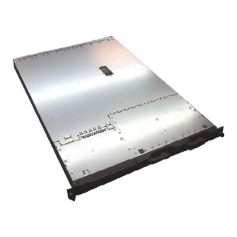
- Page 1 K2-102 (MS-9266) 1U Rackmount Server English Version G52-92661X3...
- Page 2 VOIR LA NOTICE D’INSTALLATION AVANT DE RACCORDER AU RESEAU. Micro-Star International MS-9266 This device complies with Part 15 of the FCC Rules. Operation is subject to the following two conditions: (1) this device may not cause harmful interference, and (2) this device must accept any interference received, including interference that may cause undesired operation.
-
Page 3: Copyright Notice
If a problem arises with your system and no solution can be obtained from the user’s manual, please contact your place of purchase or local distributor. Alternatively, please try the following help resources for further guidance. Visit the MSI website for FAQ, technical guide, BIOS updates, driver updates, and other information: http://www.msi.com.tw/program/service/faq/ faq/esc_faq_list.php... -
Page 4: Safety Instructions
Safety Instructions Always read the safety instructions carefully. Keep this User’s Manual for future reference. Keep this equipment away from humidity. Lay this equipment on a reliable flat surface before setting it up. The openings on the enclosure are for air convection hence protects the equip- ment from overheating. - Page 5 WEEE Statement...
-
Page 8: Table Of Contents
Top View ...................... 1-3 Front View ....................1-4 Rear View ....................1-5 System Specifications..................1-9 Mainboard Layout ....................1-12 MSI Special Features ..................1-13 PC Alert™ III ....................1-13 Chapter 2. System Hardware ................2-1 System Assembly Flowchart ................2-2 System Assembly ....................2-4 Removing the Chassis Cover .............. - Page 9 Hard Disk Connector: IDE ..................3-9 Front Panel Connector: J1 ................. 3-10 Serial Port Connector: COM 2 ................3-10 Serial ATA Connectors: JSATA1, JSATA2 (Optional) ........3-11 Fan Power Connectors: SFAN1/SFAN2/SFAN3/SFAN4/SFAN5 ...... 3-12 Rear Status LED: J20 ..................3-12 Ultra320 SCSI Connector: SCSI 1 (Optional) ............ 3-13 Slots ........................
-
Page 10: Chapter 1. Getting Started
Getting Started Chap t er 1 . Ge tting Started Getting Started The MS-9266 1U Rackmount Server is a high-performance ® barebone system powered by dual AMD Opteron processors, BCM5780, BCM5785 PCI-X Bridges, and NS PC87417/ADM1027. W ith high scalability, reliability, ease of use, and overall value, the MS-... -
Page 11: Packing Checklist
In addition, keep the box and packing materials for possible future use. Your MS-9266 1U Rackmount Server Barebone package should contain the following items: * MS-9266 1U Rackmount Server... -
Page 12: System Overview
Getting Started System Overview This section shows the configuration of the MS-9266 from different angles, and the connectors and buttons on the front and back panel. Top View 1. Proprietary Power Supply 2. Slim CD-ROM Drive 3. DIMM Slots 4. PCI Slots 5. -
Page 13: Front View
MS-9266 1U Rackmount Server Front View 1. Slim CD-ROM (optional) 2. Hot Swap SCSI (or S-ATA) HDD: HDD 1 (ID0) 3. Hot Swap SCSI (or S-ATA) HDD: HDD 2 (ID1) 4. USB Port 1 5. USB Port 2 6. (from left to right) IDE HDD Activity LED, Location LED, Info LED &... -
Page 14: Rear View
MSI Reminds You... * Please refer to Table 1. MS-9266Front Bezel & Rear I/O LEDs Definitions for more information on Power LED. ** Please refer to Table 2. MS-9266 System Error and Diagnostic LEDs Definitions for more information on Error LED. - Page 15 MS-9266 1U Rackmount Server Table 1. MS-9266 Front Bezel & Rear I/O LEDs Definitions Color State Description Power Green System operating Blink System main power off and standby power on AC power removed IDE HDD Activity Green Random blink IDE HDD access activity...
-
Page 16: Diagnostic Leds
Getting Started Table 2. MS-9266 System Error and Diagnostic LEDs Definitions Item Error LED Diagnostic LED Description/Symptoms Normal operation CPU Error LED ON Processor related problems SCSI Error LED ON SCSI hard drive Error/failure FAN Error LED ON Fan failure... -
Page 17: Usb Port
MS-9266 1U Rackmount Server 9 7 5 3 1 USB Port COM 2 SIGNAL 8 6 4 2 -Data +Data COM 2 Pin Definition DESCRIPTION DESCRIPTION Data Carrier Detect Receive Data SCSI Connector Transmit Data Data Terminal Ready Ground Data Set Ready... -
Page 18: System Specifications
Getting Started System Specifications M ainboard u MS-9166 server board u Dual AMD ® Opteron processors in 940-pin package HyperTransport u Three 16-bit links each supports 1,600 mega-transfers (MT) per second or 3.2 GB/s in each direction. Chipset u BCM5780 u BCM5785 u Super I/O controller (NS PC87417) + ADM1027 (HW Monitor) PCI-X Bridge... - Page 19 1 IDE connector, supporting up to 2 ATA-100/133 compatible devices M SI Server M anagement IPM I 1.5 (optional) u MSI-9549 BMC card (with QLogic Zircon UL BMC) and MSI iConsole AP support IPMI 1.5 (optional) u 4 pcs, 40 x 28 mm system fan...
- Page 20 Getting Started M SI Server M anagement IPM I 1.5 (optional) u MSI-9549 BMC card (with QLogic Zircon UL BMC) and MSI iConsole AP support IPMI 1.5 (option) MS-9549 BMC Card Specification BM C Chip - Qlogic Zircon UL ( ARM7 TDMI 32-bit/40MHz RISC), 128-pin PQFP...
-
Page 21: Mainboard Layout
MS-9266 1U Rackmount Server Mainboard Layout MS-9166 v2.X Server Board 1-12... -
Page 22: Msi Special Features
Getting Started MSI Special Features PC Alert™ III The PC Alert III is a utility you can find in the CD-ROM disk. The utility is just like your PC doctor that can detect the following PC hardware status during real time operation: ö... -
Page 23: Chapter 2. System Hardware
System Hardware This chapter provides instructions on the hardware installation of the MS-9266 in two sections. System Assembly illustrates how to assemble each component of the MS-9266. Rack Mounting de- scribes the procedures for mounting the unit into the rack in details. -
Page 24: System Assembly Flowchart
MS-9266 1U Rackmount Server System Assembly Flowchart The following flowchart shows basic system assembly procedures. Please note that always wear anti-static gloves when handling electrical components and exercise caution during the installation process. For more information, contact your local dealer or experienced technician. - Page 25 System Hardware INSTALL RISER CARDS REPLACE RISER CARD BRACKET INSTALL HARD DISK DRIVES CONNECT HDD, FDD, CD-ROM CABLES & POWER CORDS CHECK IF ALL PARTS ARE PROPERLY CONNECTED RESTORE CHASSIS COVER FINISH...
-
Page 26: System Assembly
MS-9266 1U Rackmount Server System Assembly Removing the Chassis Cover Locate the release button on the chassis c over. Lift the release button to the upright p os i t i on . P u s h th e c h as s i s c over f orward. -
Page 27: Restoring The Chassis Cover
System Hardware Restoring the Chassis Cover 1. Replace the front chassis cover and slide it backwards. Replace the rear chassis cover and slide it forwards. 2. Push down the lever to fasten the chassis. - Page 28 MS-9266 1U Rackmount Server CPU and Heatsink 1. Locate the First and Second CPU 2. Lift the CPU lever up to a 90 degree sockets. angle. (If you plan on installing single CPU, use the first CPU socket.) 1st CPU Socket...
- Page 29 7. Place the heatsink on top of the CPU. 8. Screw the heatsink to the chassis. MSI Reminds You... To ensure proper cooling, make sure the heatsinks & the fan duct are properly installed.
-
Page 30: Ddr Memory
MS-9266 1U Rackmount Server DDR Memory Locate the DIMM slots. Install at least two DDR modules on the slots. The plastic clip at each side of the DIMM slot will automati-cally close. MSI Reminds You... Memory modules “in pairs” must be of the same type and size. -
Page 31: Pci Expansion Card
System Hardware PCI Expansion Card Remove the clip from the chassis. Take out the I/O shield on the first PCI slot. Insert the add-on card to the PCI slot. - Page 32 MS-9266 1U Rackmount Server Replace the clip. Follow the procedures described earlier to install the second PCI Card. 2-10...
-
Page 33: Pci Riser Card (Optional)
System Hardware PCI Riser Card (Optional) Apart from the standard PCI riser cards assembled in the system, an optional riser card is available upon request. Please refer to the following for detailed specs and the instructions on riser card installation. Standard PCI Riser Cards: MS-95D7 MS-95D7: one 64-bit/100MHz PCI-X slot Optional PCI Riser Card: M S-95D8... -
Page 34: Serial Ata/Scsi Hard Disk Drives (Optional)
MS-9266 1U Rackmount Server Serial ATA/SCSI Hard Disk Drives (Optional) Unlock the HDD device holder and pull it out from the chassis. Screw the hard disk to the HDD device holder. 2-12... - Page 35 System Hardware Slide the HDD device holder into the chas- sis and push it backward until you hear a “click” sound to secure the holder. USB tray You may pull the USB tray open to rest any USB device on it. 2-13...
-
Page 36: Rack Mounting
MS-9266 1U Rackmount Server Rack Mounting Take out the rail set for rack mounting. rail set Position the rail to the rack cabin. Rear Right Press the button to push the locking tab forward. The rail will secure itself to the cabin. - Page 37 System Hardware Position the rail to the rack cabin. Front Right Press the button to push the locking tab forward. The rail will secure itself to the cabin. Screw to secure the rail on the front. 2-15...
- Page 38 MS-9266 1U Rackmount Server Follow the same procedures as men- tioned earlier in this section to screw the left rail on the front and rear. Align the 1U rackmount server to the rails and push it backward until it reaches the end.
-
Page 39: Os Installation Guide
System Hardware OS Installation Guide Notice Before you install the server opreationg system, please do refer the installation guide in the driver CD. There are some specific steps to take before installing. 2-17... -
Page 40: Chapter 3. Mainboard Hardware
Mainboard Hardware Chapter 3. Mainboard Hardware Mainboard Hardware This chapter provides you with the information about hard- ware setup procedures. W hile doing the installation, be careful in holding the components and follow the installation procedures. For some components, if you install in the wrong orientation, the compo- nents will not work properly. -
Page 41: Quick Components Guide
MS-9266 1U Rackmount Server Quick Components Guide JBAT1, J3 PCI-E/PCI-X Slots, p.3-14 p.3-16 IDE, SCSI1, p.3-9 p.3-13 J1, p.3-10 COM 2, PC IE 1 C O M 2 p.3-10 JM G T1 SATA1/2, p.3-11 JPW R 1 I D E... -
Page 42: Central Processing Unit: Cpu
Mainboard Hardware Central Processing Unit: CPU ® ® The mainboard supports Single AMD Opteron UP or Dual AMD Opteron DP™ processor(s). The mainboard uses two CPU sockets called Socket 940 for easy CPU installation. You can install SINGLE or DUAL CPUs on the mainboard to meet your own needs. -
Page 43: Cpu Installation Procedures For Socket 940
MS-9266 1U Rackmount Server CPU Installation Procedures for Socket 940 Open Lever 1. Make sure that the computer is turned off, and the power cord disconnected before installing the CPU. 2. Pull the lever sideways away from the socket, and raise it up to a 90-degree angle. -
Page 44: Memory
4 DIMMs 2 CPUs @ Socket1 & Socket 2 Slot 1&2&3&4&5&6 with 6 DIMMs 2 CPUs @ Socket1 & Socket 2 Slot 1&2&3&4&5&6&7&8 with 8 DIMMs MSI Reminds You... Memory modules “in pairs” must be of the same type and size. -
Page 45: Installing Ddr Modules
MS-9266 1U Rackmount Server Installing DDR Modules The DDR DIMM has only one notch on the center of module. The module will only fit in the right orientation. Insert the DIMM memory module vertically into the DIMM slot. Then push it in until the golden finger on the memory module is deeply inserted in the socket. -
Page 46: Power Supply
Mainboard Hardware Power Supply The mainboard supports SSI power supply for the power system. Before inserting the power supply connector, always make sure that all components are installed properly to ensure that no damage will be caused. 18-Pin Main Power Supply Connector: J8 This connector provides power supply to the system board. - Page 47 MS-9266 1U Rackmount Server 12V_1 12V_2 12V_1 I2C_A0 12V_3 12V_2 I2C_A1 12V_4 12V_3 I2C_A2 RET1 12V_4 RET2 I2C_CLK 5V_1 RET3 I2C_DATA 5V_2 RET4 I2C_INT 5V_3 RET5 5V_1 RET6 5V_2 PRES_DET# RET7 5V_3 RESET RET8 5V_4 GND1 RET9 GND2 RET10 GND3...
-
Page 48: Sm Card 3Rd I2C Bus Connector: Jsmb1
Mainboard Hardware Connectors SM Card 3rd I2C Bus Connector: JSMB1 The mainboard provides one I2C (also known as I C) Bus connector for users to connect to System Management Bus (SMBus) interface. JSMB1 Pin Definition SIGNAL JSMB1 DATA ALT# Hard Disk Connector: IDE The mainboard has a 32-bit Enhanced PCI IDE and Ultra DMA 33/66/100/133 controller that provides PIO mode 0~4, Bus Master, and Ultra DMA 33/66/100/133 function. -
Page 49: Front Panel Connector: J1
MS-9266 1U Rackmount Server Front Panel Connector: J1 The mainboard provides one front panel connector for electrical connection to the front panel switches and LEDs. J1 Pin Definition Description Description SM_PWRLED# FP2SW_RST# Unused +5VSB Unused +5VSB SMB_2_DATA +5VSB SMB_2_CLK Unused... -
Page 50: Serial Ata Connectors: Jsata1, Jsata2 (Optional)
Take out the dust cover and connect to the hard disk devices Optional Serial ATA cable Connect to JSATA1 or JSATA2 MSI Reminds You... Please do not fold the Serial ATA cable into 90-degree angle. Otherwise, data loss may occur during transmission. 3-11... -
Page 51: Fan Power Connectors: Sfan1/Sfan2/Sfan3/Sfan4/Sfan5
SFAN4 MSI Reminds You... 1. Always consult the vendors for proper CPU cooling fan. 2. SFAN supports the fan control. MS-9266 will automatically control the CPU fan speed according to the system temperature. Rear Status LED: J20 The LED shows the error and power status. -
Page 52: Ultra320 Scsi Connector: Scsi 1 (Optional)
Mainboard Hardware Ultra320 SCSI Connector: SCSI 1 (Optional) SCSI (Small Computer System Interface) is a hardware interface that allows for connection of up to 15 peripheral devices. The mainboard provides one SCSI channel (SCSI 1) for you to connect SCSI devices such as SCSI hard disks. 68-Pin Ultra320 SCSI Connector Description Description... - Page 53 MS-9266 1U Rackmount Server Jumpers The motherboard provides the following jumpers for you to set the computer’s function. This section will explain how to change your motherboard’s function through the use of jumpers. Clear CMOS Jumper: JBAT1 There is a CMOS RAM onboard that has a power supply from external battery to keep the data of system configuration.
-
Page 54: Slots
Slots SO DIMM (Small Outline DIMM): J15 The SO DIMM has 144 pins and supports a full 64-bit transfer. It is specifically designed for users to install MSI’s proprietary server management tool -- MSI BMC (Baseboard Management Controller) card. COM1_DI(I) -
Page 55: Pci (Peripheral Component Interconnect) Slots
MS-9266 1U Rackmount Server PCI (Peripheral Component Interconnect) Slots The motherboard provides one 64-bit PCI-X slot, and two PCI Express x8 slots. one PCI-E slot is fixed, the other slot can use the plug-in riser card to expand one PCI- E or one PCI-X slot. -
Page 56: Chapter 4. Bios Setup
SETUP. ² You want to change the default settings for customized features. MSI Reminds You... 1. The items under each BIOS category described in this chapter are under continuous update for better system performance. -
Page 57: Entering Setup
MS-9266 1U Rackmount Server Entering Setup Power on the computer and the system will start POST (Power On Self Test) process. W hen the message below appears on the screen, press <F2> key to enter Setup. Press F2 to enter SETUP If the message disappears before you respond and you still wish to enter Setup, restart the system by turning it OFF and On or pressing the RESET button. -
Page 58: Getting Help
BIOS Setup Getting Help After entering the Setup menu, the first menu you will see is the Main Menu. M ain M enu The main menu lists the setup functions you can make changes to. You can use the arrow keys ( to select the item. -
Page 59: The Menu Bar
MS-9266 1U Rackmount Server The Menu Bar Once you enter PhoenixBIOS Setup Utility, the Main Menu will appear on the screen. On the Main Menu screen, you will see basic BIOS settings including system time & date, and the setup categories the BIOS supplies. Use Arrow keys to move among the items and menus, and make changes to the settings. -
Page 60: The Main Menu
BIOS Setup The Main Menu The items inside the Main menu are for basic system information and configuration. Each item includes none, one or more setup items. Use the Up/Down arrow keys or <Tab> to highlight the item or field you want to modify and use the <+> or <->... - Page 61 MS-9266 1U Rackmount Server Type Select how to define the HDD parameters LBA Mode Control Enabling LBA causes Logical Block Ad- dressing to be used in place of Cylinders, Heads and Sectors. 32-Bit I/O Enables 32-bit communication between CPU and IDE card...
- Page 62 BIOS Setup HDD Post Write Buffer This setting is used to increase the performance of the HDD. The settings are: [Disabled], [Enabled]. Large Disk Access M ode Select DOS if you have DOS. Select Other if you have another operating system such as UNIX.
-
Page 63: The Advanced Menu
MS-9266 1U Rackmount Server The Advanced Menu Items in the menu are divided into 7 sub-menus. Each sub-menu provides more settings. To enter the sub-menu, highligh the sub-menu you want to configure and press <Enter>. Install O/S Select the operating system installed on your system whic h you will use most commonly. - Page 64 BIOS Setup Halt On Error The setting determines whether the system will stop if an error is detected at boot. Available options are: [Yes], [No]. Chipset Configuration The sub-menu is used to configure chipset features for optimal system performance. ACPI P-State This item is to activate the ACPI (Advanced Configuration and Power Manage- ment Interface) Function.
- Page 65 MS-9266 1U Rackmount Server Dram Bank Interleave Interleave memory blocks across dram chip selects. Options: [Auto], [Disabled]. Node M emory Interleave Interleave memory blocks across Processor Nodes. BIOS will AUTO detect the capability of Memory System. Options: [Disabled], [AUTO]. ACPI SRAT Table...
- Page 66 BIOS Setup PCI Configuration Press PgUp/<+> or PgDn/<-> to PCI Configuration. The following submenu will appear: Planar PXE/DHCP Priority Use this feature to select whether to set the planar Ethernet PXE/DHCP option ROM as the highest priority option ROM after Video. This causes the PXE/ DHCP option ROM to execute before the PCI Device Boot Priority is checked POST.
- Page 67 MS-9266 1U Rackmount Server Serial port A/B Setting to [Enabled] allows users to configure the base I/O address and IRQ of Port A/Port B manually. Selecting [Auto] allows BIOS to automatically determine the correct base I/O port address. Options: [Enabled], [Disabled], [Auto].
- Page 68 BIOS Setup Console connection This feature indicates whether the console is connected directly to the system or a modem is used for connection. Options: [Direct], [Via modem]. Baud Rate It allows you to select delay befor key repeat. Options: [300], [1200], [2400], [9600], [19.2K], [38.4K], [57.6K], [115.2K].
- Page 69 MS-9266 1U Rackmount Server Clear all DMI event logs Setting this to Yes will clear the DMI event log after rebooting. Options: [Yes], [No]. Event Logging Select [Enabled] to allow logging of DMI events. Options: [Enabled], [Disabled]. Clear error logs Press the item to clear error logs.
-
Page 70: The Security Menu
BIOS Setup The Security Menu This section lets you set security passwords to control access to the system at boot time and/or when entering the BIOS setup program. It also allows you to set virus protection at hard disk boot sector. Supervisor Password Is/User Password Is It shows the preset supervisor/user password. -
Page 71: The Power Menu
MS-9266 1U Rackmount Server The Power Menu Use this menu to specify your settings for Power Management. Remember that the options available depend upon the hardware installed in your system. Resume On M odem Ring Select On to wake up system when an incoming call is detected on the modem. -
Page 72: The Boot Menu
BIOS Setup The Boot Menu Use this menu to arrange to specify the priority of the devices from which the BIOS will attempt to boot the Operating System. CD-ROM Drive, Removable Devices, Hard Drive These are the generic types of devices on your system from which you can boot an operating system. -
Page 73: The Exit Menu
MS-9266 1U Rackmount Server The Exit Menu The following sections describe each of the options on this menu. Note that <Esc> does not exit this menu. You must select one of the items from the menu or menu bar to exit.