Table of Contents
Advertisement
Advertisement
Table of Contents

Related Manuals for MSI 915GLM-V


Summary of Contents for MSI 915GLM-V
- Page 1 915PM/915GM/915GVM/915PLM/910GLM MS-7033 (v1.X) M-ATX Mainboard G52-M7033X5...
-
Page 2: Fcc-B Radio Frequency Interference Statement
Manual Rev: 1.1 Release Date: April 2005 FCC-B Radio Frequency Interference Statement This equipment has been tested and found to comply with the limits for a class B digital device, pursuant to part 15 of the FCC rules. These limits are designed to provide reasonable protection against harmful interference when the equipment is operated in a commercial environment. -
Page 3: Copyright Notice
Copyright Notice T he material in this document is the intellec tual property of M ICRO-STAR INTERNATIONAL. W e take every care in the preparation of this document, but no guarantee is given as to the correctness of its contents. Our products are under continual improvement and we reserve the right to make changes without notice. -
Page 4: Technical Support
Alternatively, please try the following help resources for further guidance. † Visit the MSI homepage & FAQ site for technical guide, BIOS updates, driver updates, and other information: http://www.msi.com.tw & http://www.msi. -
Page 5: Table Of Contents
CONTENTS FCC-B Radio Frequency Interference Statement ............ii Copyright Notice ......................iii Revision History ......................iii Technical Support ......................iv Safety Instructions ......................iv Chapter 1. Getting Started ..................1-1 Mainboard Specifications ................... 1-2 Mainboard Layout ....................1-4 Packing Contents ....................1-5 Chapter 2. - Page 6 CD-In Connector: JCD1 ................2-18 Front Panel Audio Connector: JAUD1 ............2-18 Serial Port Connector: JCOM2 ..............2-19 Front USB Connectors: JUSB1 & JUSB2 ..........2-19 SPDIF Connector: JSPD1 ................2-20 IEEE 1394 Connectors: JFW1 (optional) ..........2-21 Jumpers ......................2-21 Clear CMOS Jumper: JBAT1 ..............
- Page 7 View Serial Number of Hard Drive ............4-10 Duplicate Critical RAID 1 Array ..............4-11 Rebuild Broken RAID 0/0+1 Array ............4-12 Installing Software .................... 4-14 Install Driver in W indows XP/2000 ............4-14 Installation of VIA IDE RAID Utility ............. 4-15 Using VIA RAID Tool ..................
-
Page 8: Chapter 1. Getting Started
Getting Started Chap t er 1 . Ge tting Started Getting Started T hank you f or c hoos ing the 915PM /915PLM /915G M / 915GVM/910GLM (MS-7033) v1.X M-ATX mainboard. The 915PM/ ® 915PLM /915GM/915GVM/910GLM mainboard is based on Intel ®... -
Page 9: Mainboard Specifications
Pentium 4 Prescott (LGA775) processors in LGA775 package † Supports 533MHz, 800MHz FSB † Supports 2004 Performance FMB CPU VR Design † Supports 3 or 4 pin CPU Fan Pin-Header with Fan Speed Control (For the latest information about CPU, please visit http://www.msi.com.tw/program/ products/mainboard/mbd/pro_mbd_cpu_support.php) Chipset † Intel ®... - Page 10 Getting Started † Support 2 Serial ATA ports On-Board Peripherals † On-Board Peripherals include: - 1 floppy port supports 1 FDD with 360K, 720K, 1.2M, 1.44M and 2.88Mbytes - 2 serial ports, Com1 on Rear IO, Com2 via pin header(IO bracket is optional) - 1 parallel port supports SPP/EPP/ECP mode - 1 Line-In / Line-Out / MIC-In / Surround Speaker Out / Center-Subwoofer Speaker Out / Surround Back Speaker Out...
-
Page 11: Mainboard Layout
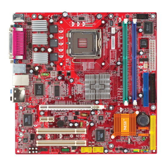
M S-7033 M -ATX M ainboard Mainboard Layout Top : mouse Bottom: keyboard JCOM2 CPU_FAN1 CPU_FAN2 ATX1 Top : Parallel Port Bottom: COM port VGA port (optional) T:IEEE 1394 (optional) JPW1 B:USB port Intel T: LAN jack (optional) 915P/915G/915GV/ B: USB ports 910GL/915PL RTL8100C/ Line-In... -
Page 12: Packing Contents
Getting Started Packing Contents MSI Driver/Utility CD Back IO Shield MSI motherboard User’s Guide... -
Page 13: Chapter 2. Hardware Setup
Hardware Setup Chapter 2. Hardware Setup Hardware Setup This chapter tells you how to install the CPU, memory modules, and expansion cards, as well as how to setup the jumpers on the mainboard. Also, it provides the instructions on connecting the periph- eral devices, such as the mouse, keyboard, etc. -
Page 14: Quick Components Guide
M S-7033 M -ATX M ainboard Quick Components Guide CPUF_FAN1 JPW1, p.2-9 CPU, p.2-3 CPUF_FAN2, DDR DIMMs, p.2-7 p.2-14 JCOM2, p.2-19 Back Panel ATX1, p.2-9 I/O, p.2-10 SYSFAN1, p.2-14 FDD1, p.2-14 IDE1, p.2-15 PCI Express x16, p.2-22 PCI Express x1, p.2-22 IDE2, p.2-15 PCI Slots 2/3,... -
Page 15: Central Processing Unit: Cpu
If you do not have the CPU, contact your dealer to purchase and install them before turning on the computer. For the latest information about CPU, please visit http://www.msi.com.tw/ program/products/mainboard/mbd/pro_mbd_cpu_support.php. MSI Reminds You... -
Page 16: Cpu, Heatsink & Fan Installation
M S-7033 M -ATX M ainboard CPU, Heatsink & Fan Installation W hen you are installing the CPU, make sure the CPU has a heat sink/ cooler fan attached on the top to prevent overheating. If you do not have the heat sink/cooler fan, contact your dealer to purchase and install them before turning on the computer. - Page 17 Hardware Setup 5. Lift the load lever up and open the 6. After confirming the CPU direction load plate. for correction mating, put down the CPU in the s ocket housing frame. Be sure to grape on the edge of the substrate. Note that the alignment keys are matched.
- Page 18 MSI Reminds You... 1. Confirm if your CPU heatsink/cooler is firmly installed before turning on your system. 2. Check the information in PC Health Status of H/W M onitor in BIOS (refer to p.3-20 for details) for the CPU temperature.
-
Page 19: Memory
The mainboard provides 2 slots for 184-pin DDR SDRAM DIMM (Double In-Line Memory Module) modules and supports the memory size up to 2GB. You can install DDR266/ 333/400 modules on the DDR DIMM slots (DDR 1~2). For the updated supporting memory modules, please visit http://www.msi.com.tw/ program/products/mainboard/mbd/pro_mbd_trp_list.php. DDR DIMM Slots... -
Page 20: Dimm Module Combination
The plastic clip at each side of the DIMM slot will automatically close. Notch Volt MSI Reminds You... You can barely see the golden finger if the module is properly in- serted in the socket. -
Page 21: Power Supply
JPW1 Pin Definition SIGNAL JPW1 MSI Reminds You... 1. These two connectors connect to the ATX power supply and have to work together to ensure stable operation of the mainboard. 2. Power supply of 350 watts (and above) is highly recommended for system stability. -
Page 22: Back Panel
M S-7033 M -ATX M ainboard Back Panel The back panel provides the following connectors: L-In Surround IEEE1394 Parallel (Optional) (Optional) M ou se Center/ Subwoofer VGA port Keyboard COM port USB Ports L-Out Surround (Optional) Back Mouse/Keyboard Connector ® The mainboard provides a standard PS/2 mouse/keyboard mini DIN connector ®... -
Page 23: Serial Port Connector
Hardware Setup Serial Port Connector The mainboard offers one 9-pin male DIN connector as the serial port. The port is a 16550A high speed communication port that sends/receives 16 bytes FIFOs. You can attach a serial mouse or other serial devices directly to the connector. Pin Definition 1 2 3 4 5 SIGNAL... -
Page 24: Lan (Rj-45) Jack (Optional)
M S-7033 M -ATX M ainboard LAN (RJ-45) Jack (optional) The mainboard provides 1 standard RJ-45 jack for connection to single Local Area Network (LAN). This Giga-bit LAN enables data to be transferred at 1000, 100 or 10Mbps. You can connect a network cable to it. Giga-bit LAN Pin Definition SIGNAL DESCRIPTION... -
Page 25: Parallel Port Connector: Lpt1
Hardware Setup Parallel Port Connector: LPT1 The mainboard provides a 25-pin female centronic connector as LPT. A parallel port is a standard printer port that supports Enhanced Parallel Port (EPP) and Ex- tended Capabilities Parallel Port (ECP) mode. Pin Definition SIGNAL DESCRIPTION STROBE... -
Page 26: Connectors
Sensor SYSFAN1 CPU_FAN1 CPU_FAN2 MSI Reminds You... 1. Always consult the vendors for proper CPU cooling fan. 2. CPUFAN2 supports the fan control. Fan/heatsink with 3 or 4 fins are both available. Meanwhile, you can install Core Center util- ity (refer to Chapter 4 for details) that will automatically control the CPU fan speed according to the actual CPU temperature. -
Page 27: Hard Disk Connectors: Ide1 & Ide2 (Optional)
The default setting of IDE2 is standard IDE. RAID function can be enabled by BIOS setting. MSI Reminds You... If you install two hard disks on cable, you must configure the second drive to Slave mode by setting its jumper. Refer to the hard disk documentation supplied by hard disk vendors for jumper setting instructions. -
Page 28: Serial Ata Hdd Connectors: Sata1 & Sata2
Take out the dust cover and connect to the hard disk devices Connect to serial ATA ports MSI Reminds You... Please do not fold the serial ATA cable in a 90-degree angle, which will cause the loss of data during the transmission. 2-16... -
Page 29: Front Panel Connectors: Jfp1 & Jfp2
Hardware Setup Front Panel Connectors: JFP1 & JFP2 The mainboard provides two front panel connectors for electrical connection ® to the front panel switches and LEDs. JFP1 is compliant with Intel Front Panel I/O Connectivity Design Guide. Power Power Speaker Switch JFP2 JFP1... -
Page 30: Cd-In Connector: Jcd1
M S-7033 M -ATX M ainboard CD-In Connector: JCD1 The connector is for CD-ROM audio connector. JCD1 Front Panel Audio Connector: JAUD1 The JAUD1 front panel audio connector allows you to connect to the front ® panel audio and is compliant with Intel Front Panel I/O Connectivity Design Guide. -
Page 31: Serial Port Connector: Jcom2
Hardware Setup Serial Port Connector: JCOM2 The mainboard offers one serial port JCOM2. It is 16550A high speed communication ports that senda/receivea/ 16 bytes FIFOs. You can attach a serial mouse or other serial device directly to it. Pin Definition SIGNAL DESCRIPTION Data Carry Detect... -
Page 32: Spdif Connector: Jspd1
M S-7033 M -ATX M ainboard SPDIF Connector: JSPD1 The connector is used to connect SPDIF (Sony & Philips Digital Interconnect Format) interface for digital audio transmission. JSPD1 Pin Definition SIGNAL VCCS JSPD1 SPDIF0 Connected to JSPD1 The JSPD1 supports SPDIF output only and can be connected to an external SPDIF Bracket for digital audio transmission. -
Page 33: Jumpers
JBAT1 Keep Data Clear Data MSI Reminds You... You can clear CMOS by shorting 2-3 pin while the system is off. Then return to 1-2 pin position. Avoid clearing the CMOS while the system is on; it will damage the mainboard. -
Page 34: Slots
PCI Express x1 supports transfer rate of 250 MB/s. PCI Express x16 slot PCI Express x1 slot MSI Reminds You... 1. The PCI Express x16 slot also supports ADD2 interface card when it is presented on PCI Express x16 slot. -
Page 35: Pci (Peripheral Component Interconnect) Slots
Hardware Setup PCI (Peripheral Component Interconnect) Slots The PCI slots allow you to insert the expansion cards to meet your needs. W hen adding or removing expansion cards, make sure that you unplug the power supply first. Meanwhile, read the documentation for the expansion card to make any necessary hardware or software settings for the expansion card, such as jumpers, switches or BIOS configuration. -
Page 36: Chapter 3. Bios Setup
SETUP. ² You want to change the default settings for customized features. MSI Reminds You... 1. The items under each BIOS category described in this chapter are under continuous update for better system performance. Therefore, the description may be slightly different from the latest BIOS and should be held for reference only. -
Page 37: Entering Setup
M S-7033 M -ATX M ainboard Entering Setup Power on the computer and the system will start POST (Power On Self Test) process. W hen the message below appears on the screen, press <DEL> key to enter Setup. Press DEL to enter SETUP If the message disappears before you respond and you still wish to enter Setup, restart the system by turning it OFF and On or pressing the RESET button. -
Page 38: Getting Help
<F1>. The Help screen lists the appropriate keys to use and the possible selections for the highlighted item. Press <Esc> to exit the Help screen. MSI Reminds You... The items under each BIOS category described in this chapter are under continuous update for better system performance. Therefore, the description may be slightly different from the latest BIOS and should be held for reference only. -
Page 39: The Main Menu
M S-7033 M -ATX M ainboard The Main Menu ® Once you enter Award BIOS CMOS Setup Utility, the Main Menu (figure below) will appear on the screen. The Main Menu allows you to select from twelve setup functions and two exit choices. Use arrow keys to select among the items and press <Enter> to accept or enter the sub-menu. - Page 40 BIOS Setup Load Fail-Safe Defaults Use this menu to load the BIOS values for the best system performance, but the system stability may be affected. Load Optimized Defaults Use this menu to load factory default settings into the BIOS for stable system perfor- mance operations.
-
Page 41: Standard Cmos Features
M S-7033 M -ATX M ainboard Standard CMOS Features The items in Standard CMOS Features Menu are divided into 11 categories. Each category includes no, one or more than one setup items. Use the arrow keys to highlight the item and then use the <PgUp> or <PgDn> keys to select the value you want in each item. - Page 42 BIOS Setup If you select [Manual], related information is asked to be entered to the following items. Enter the information directly from the keyboard. This information should be provided in the documentation from your hard disk vendor or the system manufacturer. Access M ode The settings are CHS, LBA, Large, Auto.
-
Page 43: Advanced Bios Features
In this way, the system performance is highly improved. If you disable the function, the processor will use only one core to execute the instructions. Settings: [Enabled], [Disabled]. MSI Reminds You... Enabling the functionality of Hyper-Threading Technology for your com- puter system requires ALL of the following platform Components: ®... - Page 44 BIOS Setup MPS Table Version This field allows you to select which MPS (Multi-Processor Specification) version to be used for the operating system. You need to select the MPS version supported by your operating system. To find out which version to use, consult the vendor of your operating system.
- Page 45 These items allow you to set the sequence of boot devices where AMIBIOS attempts to load the operating system. MSI Reminds You... Available settings for “1st/2nd/3rd Boot Device” vary depending on the bootable devices you have installed. For example, if you did not install a floppy drive, the setting “Floppy”...
-
Page 46: Advanced Chipset Features
BIOS Setup Advanced Chipset Features MSI Reminds You... Change these settings only if you are familiar with the chipset. DRAM Timing Selectable Selects whether DRAM timing is controlled by the SPD (Serial Presence Detect) EEPROM on the DRAM module. Setting to [Auto By SPD] enables DRAM timings and the following related items to be determined by BIOS based on the configurations on the SPD. - Page 47 M S-7033 M -ATX M ainboard DRAM RAS# Precharge (tRP) W hen the DRAM Timing Control is set to [Manual], this field is adjustable. This setting controls the number of cycles for Row Address Strobe (RAS) to be allowed to precharge.
- Page 48 BIOS Setup PCI Express Port You can set PCI Express port. Setting options: [Disabled], [Enabled], [Auto]. PCI-E Compliancy Mode It allows you select the PCI-E compliant mode. Setting options: [v1.0], [v1.0a]. ** VGA Setting ** (Not for 915P) Init Display First This item specifies which VGA card is your primary graphics adapter.
-
Page 49: Integrated Peripherals
M S-7033 M -ATX M ainboard Integrated Peripherals RAID USB Controller Select [Enabled] if your system contains a Universal Serial Bus (USB) controller and you have USB peripherals. Setting options: [Enabled], [Disabled]. USB 2.0 Controller This item is used to [Enabled] / [Disabled] the USB 2.0 Support. Setting options: [Enabled], [Disabled]. - Page 50 BIOS Setup Onboard LAN The item enables or disables the onboard LAN controller. Setting options: [Enabled], [Disabled]. OnBoard 1394 (optional) This setting is used to enable/disable the onboard IEEE 1394 controller. Setting options: [Enabled], [Disabled]. IO Devices Configuration Press <Enter> and the following sub-menu appears: POWER ON Function This controls how the PS/2 mouse or keyboard can power on the system.
- Page 51 M S-7033 M -ATX M ainboard Onboard COM Port 1/COM Port 2 This item specifies the base I/O port address and IRQ for the onboard Serial Port 1 (LPT1B)/Serial Port 2 (JCOM1). Selecting [Auto] allows BIOS to automatically determine the correct base I/O port address. Setting options: [Disabled], [3F8/ IRQ4], [2F8/IRQ3], [3E8/IRQ4], [2E8/IRQ3], [Auto].
- Page 52 BIOS Setup ECP Mode Use DMA The ECP mode has to use the DMA channel, so choose the onboard parallel port with the ECP feature. After selecting it, the following message will appear: “ECP Mode Use DMA.” At this time, the user can choose between DMA channel [3] or [1].
- Page 53 M S-7033 M -ATX M ainboard IDE Primary Master/Slave Ultra DMA Ultra DMA 33/66/100/133 implementation is possible only if your IDE hard drive supports it and the operating environment includes a DMA driver (Windows ME, XP or a third-party IDE bus master driver). If your hard drive and your system software both support Ultra DMA/33, Ultra DMA/66, Ultra DMA/100 and Ultra DMA/133, select [Auto] to enable BIOS support.
-
Page 54: Power Management Setup
BIOS Setup Power Management Setup ACPI Standby State This item specifies the power saving modes for ACPI function. Options are: [S1/POS] The S1 sleep mode is a low power state. In this state, no system context is lost (CPU or chipset) and hardware maintains all system context. - Page 55 M S-7033 M -ATX M ainboard Wake Up Event Setup Press <Enter> and the following sub-menu appears: PCI Express PME You can enable/disable PCI Express PME function. Setting options: [Enabled], [Disabled]. Resume by PCI Device (PME#) This controls how and whether the system can be powered on by the devices installed on PCI slots.
-
Page 56: Pnp/Pci Configurations
BIOS Setup PNP/PCI Configurations This section describes configuring the PCI bus system and PnP (Plug & Play) feature. PCI, or Peripheral Component Interconnect, is a system which allows I/O devices to operate at speeds nearing the speed the CPU itself uses when communicating with its special components. -
Page 57: H/W Monitor
M S-7033 M -ATX M ainboard H/W Monitor This section shows the status of your CPU, fan, overall system status, etc. Monitor function is available only if there is hardware monitoring mechanism onboard. CPU Warning Temperature This item is used to specify a thermal limit for CPU. If CPU temperature reaches the specified limit, the system will issue a warning and allows you to prevent the CPU overheating problem. - Page 58 BIOS Setup PC Health Status Press <Enter> and the following sub-menu appears. CPU/System Temperature, CPU/System/Power FAN Speed, Vcore, +5.0V, +12. 0V, VBAT (V), +5VSB These items display the current status of all of the monitored hardware devices/ components such as CPU voltages, temperatures and all fans’ speeds. 3-23...
-
Page 59: Frequency/Voltage Control
M S-7033 M -ATX M ainboard Frequency/Voltage Control Use this menu to specify your settings for frequency/voltage control. Current CPU Clock It shows the current clock frequency of CPU. (Read-only) Adjust CPU Ratio End users can overclock the processor (only if the processor supports so) by speci- fying the CPU ratio (clock multiplier) in this field. - Page 60 BIOS Setup M emory Voltage Adjusting the DDR voltage can increase the DDR speed. Any changes made to this setting may cause a stability issue, so changing the DDR voltage for long-term purpose is NOT recommended. PCI Express Voltage PCI Express voltages are adjustable in the field, allowing you to increase the perfor- mance of your AGP/PCI Express display card when overclocking, but the stability may be affected.
-
Page 61: Load Fail-Safe/Optimized Defaults
M S-7033 M -ATX M ainboard Load Fail-Safe/Optimized Defaults The two options on the main menu allow users to restore all of the BIOS settings to the default Fail-Safe or Optimized values. The Optimized Defaults are the default values set by the mainboard manufacturer specifically for optimal performance of the mainboard. -
Page 62: Set Supervisor/User Password
Security Option of the Advanced BIOS Feature menu. If the Security Option is set to [System], the password is required both at boot and at entry to Setup. If set to [Setup], password prompt only occurs when you try to enter Setup. MSI Reminds You... About Supervisor Password & User Password: Supervisor password: Can enter and change the settings of the setup menu. -
Page 63: Chapter 4. Introduction To Via Vt6410 Ide Raid
Introduction to VIA VT6410 IDE RAID Chapter 5. Intel ICH6R RAID Introduction Introduction to VIA VT6410 IDE RAID The VIA IDE RAID solution uses the VT6410 chip (a one-channel ATA 133 solution) as a RAID controller. The RAID software is a W indows-based software utility. -
Page 64: Introduction
M S-7033 M -ATX M ainboard Introduction This section gives a brief introduction on the RAID-related background knowl- edge and a brief introduction on VIA IDE RAID Host Controller. For users wishing to install their VIA IDE RAID driver and RAID software, proceed to Installing Software section. -
Page 65: Raid 1 (Mirroring)
Introduction to VIA VT6410 IDE RAID RAID 1 (Mirroring) RAID 1 writes duplicate data onto a pair of drives and reads both sets of data in parallel. If one of the mirrored drives suffers a mechanical failure or does not respond, the remaining drive will continue to function. -
Page 66: Bios Configuration
<Enter> to call out the list of creation steps. The main interface of BIOS configuration utility is as below: MSI Reminds You... 1. The default setting of VIA IDE is standard IDE. It requires user to change BIOS setting to support RAID function. -
Page 67: Create Disk Array
Create Disk Array Use the up and down arrow keys to select the Create Array command and press <Enter>. MSI Reminds You... The “Channel”, “Drive Name”, “Mode” and “Size (GB)” in the following example might be different from your system. - Page 68 M S-7033 M -ATX M ainboard After array mode is selected, there are two methods to create a disk array. One method is “Auto Setup” and the other one is “Select Disk Drives”. Auto Setup allows BIOS to select the disk drives and create arrays automatically, but it does not duplicate the mirroring drives even if the user selected Create and dupli- cate for RAID 1.
- Page 69 Introduction to VIA VT6410 IDE RAID MSI Reminds You... Even though 64KB is the recommended setting for most users, you should choose the block size value which is best suited to your specific RAID usage model. 4KB: For specialized usage models requiring 4KB blocks...
-
Page 70: Delete Disk Array
M S-7033 M -ATX M ainboard Delete Disk Array A RAID can be deleted after it has been created. To delete a RAID, use the following steps: 1. Select Delete Array in the main menu and press <Enter>. The channel column will be activated. -
Page 71: Create And Delete Spare Hard Drive
Introduction to VIA VT6410 IDE RAID Create and Delete Spare Hard Drive If a RAID 1 array is created and there are drives that do not belong to other arrays, the one that has a capacity which is equal to or greater than the array capacity can be selected as a spare drive for the RAID 1 array. -
Page 72: Select Boot Array
M S-7033 M -ATX M ainboard Select Boot Array User can select a disk array as boot device if user wants to boot operating system from an array. Boot disk array cannot be selected if the operating system does not boot from the disk array. Highlight the Select Boot Array item; press <Enter>... -
Page 73: Duplicate Critical Raid 1 Array
Introduction to VIA VT6410 IDE RAID Duplicate Critical RAID 1 Array W hen booting up the system, BIOS will detect if the RAID 1 array has any inc onsis tenc ies between us er data and backup data. If BIOS detects any inconsistencies, the status of the disk array will be marked as critical, and BIOS will prompt the user to duplicate the RAID 1 in order to ensure the backup data consist- ency with the user data. -
Page 74: Rebuild Broken Raid 0/0+1 Array
M S-7033 M -ATX M ainboard Rebuild Broken RAID 0 Array W hen booting up the system, BIOS will detect if any member disk drives of RAID has failed or is absent. If BIOS detects any disk drive failures or missing disk drives, the status of the array will be marked as broken. - Page 75 Introduction to VIA VT6410 IDE RAID 3. Choose Replacement Drive and Rebuild: This item enables users to select an already-connected hard drive to rebuild the broken array. After choosing a hard drive, the channel column will be activated. Highlight the target hard drive and press <Enter>, a warning message will appear. Press Y to use that hard drive to rebuild, or press N to cancel.
-
Page 76: Installing Software
W indows XP installation † Existing Windows XP/2000 Driver Installation 1. Insert the MSI CD into the CD-ROM drive. 2. The CD will auto-run and the setup screen will appear. 3. Under the Driver tab, click on VIA IDE RAID Drivers. -
Page 77: Installation Of Via Ide Raid Utility
† IDE RAID driver † VIA IDE RAID utility † RAID0, RAID1 & functions Insert the MSI CD and click on the VIA IDE RAID Utility to install the software. Click on this item 4-15... - Page 78 M S-7033 M -ATX M ainboard The InstallShield Wizard will begin automatically for installation. Click on the Next button to proceed the installation in the welcoming window. Select I Agree to accept the VIA Software License Agreement, and click on the Next button to continue.
- Page 79 Introduction to VIA VT6410 IDE RAID Put a check mark in the check box to install the feature you want. Then click Next button to proceed the installation. Remember to restart your computer before using this newly installed program. 4-17...
-
Page 80: Using Via Raid Tool
M S-7033 M -ATX M ainboard Using VIA RAID Tool Once the installation is complete, go to Start ---> Programs --->VIA ---> RAID to enable VIA RAID TOOL. After the software has finished installation, it will automatically start every time W indows is initiated. You may double-click on the icon shown in the system tray of the tool bar to launch the VIA RAID Tool... - Page 81 Introduction to VIA VT6410 IDE RAID Click on button to determine the viewing type of left window pane. There are two viewing types: By controllers and by device. Click on the object in the left window pane to display the status of the object in the right window pane. The following screen shows the status of Array 0---RAID 0.
- Page 82 M S-7033 M -ATX M ainboard You may also use the same button to view the statuses of Array 0---RAID 1. Click on the plus (+) symbol next to Array 0---RAID 1 to see the details of each disk. 4-20...
-
Page 83: Chapter 5. Introduction To Cmi 9880L Audio Codec
Introduction to CMI9880L Audio Codec Chapter 7. Introduction to CMI 9880L Audio Codec Introduction to CMI 9880L Audio Codec The motherboard comes with CMI9880L audio chip, which supports the brand new Azalia specification. In addition, C-Media designs a multi-stream function which allows the rear audio & front panel to play different audio sources simultaneously. -
Page 84: Installing The Audio Codec Driver
M S-7033 M -ATX M ainboard Installing the Audio Codec Driver To install C-M edia drivers: 1. Insert the MSI CD into the CD-ROM drive. The setup screen will automatically appear. 2. Click on C-M edia Azalia Audio Driver. 3. Follow the on-screen instructions to complete installation. -
Page 85: Software Configuration
Introduction to CMI9880L Audio Codec Software Configuration To have your 4-/6-/8-channel audio work, you must set appropriate configu- ration in the C-Media software application. Click the C-Media Mixer icon from the window tray on the bottom, and choose Open. Then the C-M edia 3D Audio Configuration dialogue will appear. Click on the Main Setting tab to start the configuration of the audio. - Page 86 M S-7033 M -ATX M ainboard 2. Audio Jack This part shows the audio jack on your mainboard and indicates each function. (1) Rear Panel The audio configuration shown here should be identical to the audio jacks on your mainboard. Follow the indication on it to connect the audio output devices correctly. A---- ----D B----...
- Page 87 Introduction to CMI9880L Audio Codec C. Pink connector. Click the icon in the left side and you can bring up two options to choose: “Microphone” and “Unused/Undefined”. The connector’s function de- pends on your selection. D. Black connector. Click the icon in the right side and you can bring up two options to choose: “Surround Speaker (Ls/Rs)”...
- Page 88 M S-7033 M -ATX M ainboard 3. DSP M ode: Disabled This part provides an advanced, amazing and considerate feature-dynami- cally adjustable multi-channel sound system no matter what listening appliance you are using and what application you are running. The default setting for DSP Mode is off, in which the speaker icon next to the DSP Mode an d t h e 7 .
- Page 89 Introduction to CMI9880L Audio Codec 4. DSP Mode: Enabled This part provides an advanced, amazing and considerate feature-dynami- cally adjustable multi-channel sound system no matter what listening appliance you are using and what application you are running. Click the speaker icon next to the DSP Mode and click the 7.1 Virtual SPEAKER SHIFTER button, or click the 7.1 Virtual SPEAKER SHIFTER button directly to enable this function, then all the speakers are...
-
Page 90: Mixer
M S-7033 M -ATX M ainboard Mixer 1. Multi-Stream Function CMI9880L supports an outstanding feature called Multi-Stream, which means you may play different audio sources simultaneously and let them output respectively from the indicated real panel or front panel. This feature is very helpful when 2 people are using the same computer together for different purposes. - Page 91 Introduction to CMI9880L Audio Codec In the Mixer part, you may adjust the volumes of the rear and front panels individually. (1) C-Media Rear Panel Audio photo: (2) C-Media Front Panel Audio photo: 5 - 9...
- Page 92 M S-7033 M -ATX M ainboard 2. Recording If you want to use microphone to record, usually the microphone is con- nected to the MIC jack (the pink one) in the rear audio panel. You can start recording in this case. ----A ----B A.
-
Page 93: Device Setting
Introduction to CMI9880L Audio Codec If you’d like to connect your microphone to the front audio panel, please go to the Sounds and Audio Devices Properties dialogue (path: Go to Control Panel --> Sounds, Speech and Audio Devices --> Sounds and Audio Devices --> Sounds and Audio Devices Properties, and choose Audio tab) and go to the Sound recording part. -
Page 94: Effect
M S-7033 M -ATX M ainboard Effect From this part, you may choose the sound effect you like, such as environ- ment effects, environment sizes and equalizers. You may also define your own equalizers and save them for the future usage. Information In this tab it provides some information about the Azalia Audio Configuration utility, including 3D Audio Engine, Audio Codec, Audio Driver Version, Audio Controller...