Table of Contents
Advertisement
Advertisement
Table of Contents

Related Manuals for MSI 848P Neo-V Series


Summary of Contents for MSI 848P Neo-V Series
- Page 1 865PE Neo2-V / 848P Neo-V Series MS-6788 (v2.X) ATX Mainboard G52-M6788X7...
-
Page 2: Fcc-B Radio Frequency Interference Statement
Manual Rev: 2.0 Release Date: February 2004 FCC-B Radio Frequency Interference Statement This equipment has been tested and found to comply with the limits for a class B digital device, pursuant to part 15 of the FCC rules. These limits are designed to provide reasonable protection against harmful interference when the equipment is operated in a commercial environment. -
Page 3: Copyright Notice
Copyright Notice The material in this document is the intellectual property of MICRO-STAR INTERNATIONAL. We take every care in the preparation of this document, but no guarantee is given as to the correctness of its contents. Our products are under continual improvement and we reserve the right to make changes without notice. -
Page 4: Safety Instructions
Alternatively, please try the following help resources for further guidance. Visit the MSI homepage & FAQ site for technical guide, BIOS updates, driver updates, and other information: http://www.msi.com.tw & http://www.msi. -
Page 5: Table Of Contents
FCC-B Radio Frequency Interference Statement ... ii Copyright Notice ... iii Revision History ... iii Safety Instructions ... iv Technical Support ... iv Chapter 1. Getting Started ... 1-1 Mainboard Specifications ... 1-2 Mainboard Layout ... 1-4 Chapter 2. Hardware Setup ... 2-1 Quick Components Guide ... - Page 6 CD-In Connector: CD1 ... 2-14 ATA100 Hard Disk Connectors: IDE1 & IDE2 ... 2-15 Front USB Connectors: JUSB2 & JUSB3 ... 2-15 Serial ATA HDD Connectors: SATA1, SATA2 ... 2-16 S-Bracket (SPDIF) Connector: JSP1 (Optional) ... 2-17 Front Panel Connectors: JFP1 & JFP2 ... 2-18 Front Panel Audio Connector: JAUD1 ...
-
Page 7: Chapter 1. Getting Started
Chapter 1. Getting Started Getting Started Thank you for choosing the 865PE Neo2-V / 848P Neo-V Series (MS-6788) v2.X ATX mainboard. The 865PE Neo2-V / 848P Neo-V Series is based on Intel for optimal system efficiency. Designed to fit the advanced Intel Pentium ®... -
Page 8: Mainboard Specifications
P4 Northwood / Prescott (Socket 478) processors. FSB 400MHz (for Northwood only) / 533MHz / 800MHz depending on the North Bridge integrated. Supports up to 3.4GHz or higher speed P4 processor. (For the latest information about CPU, please visit http://www.msi.com.tw/program/ products/mainboard/mbd/pro_mbd_cpu_support.php) Chipset ®... - Page 9 On-Board Peripherals On-Board Peripherals includes: - 1 floppy port supports 1 FDDs with 360K, 720K, 1.2M, 1.44M and 2.88Mbytes - 1 serial port COM1 - 1 parallel port supports SPP/EPP/ECP mode - 8 USB 2.0 ports (Rear * 4/ Front * 4) - 1 Line-In/Line-Out/Mic-In port - 1 RJ45 LAN jack (Optional) - 1 RCA SPDIF Out...
-
Page 10: Mainboard Layout
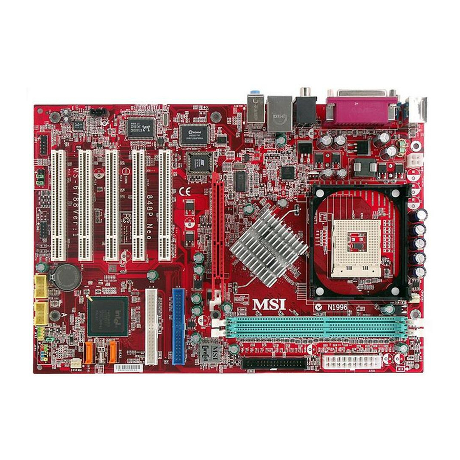
MS-6788 ATX Mainboard Mainboard Layout Top : mouse Bottom : keyboard T:SP DIF Out B:USB ports T:LAN jack (Optional) B:USB ports T:Line-In Line-Out JPW1 B:Mic BIOS Winb ond W83627THF Realtek 8110S/8100C Codec JAUD 1 JSP1 865PE Neo2-V (MS-6788 v2.X) ATX Mainboard 1 - 4 CP UFAN1 ATX Power... -
Page 11: Getting Started
PCI Slot 2 Realtek 8110S/8100C PCI Slot 3 PCI Slot 4 Codec PCI Slot 5 JAUD1 JSP1 JDB1 848P Neo-V (MS-6788 v2.X) ATX Mainboard Getting Started CP UFAN1 ATX Power Supply Intel SATA2 ICH 5 SATA1 IDE 2 IDE 1... -
Page 12: Chapter 2. Hardware Setup
Chapter 2. Hardware Setup Hardware Setup This chapter tells you how to install the CPU, memory modules, and expansion cards, as well as how to setup the jumpers on the mainboard. Also, it provides the instructions on connecting the peripheral devices, such as the mouse, keyboard, etc. -
Page 13: Quick Components Guide
MS-6788 ATX Mainboard Quick Components Guide Back Panel I/O, p.2-10 JPW1, p.2-9 AGP Slot, p.2-22 PCI Slots, p.2-22 CD1, p.2-14 JSP1, p.2-17 JAUD1, p.2-19 2 - 2 CPUFAN1, p.2-14 CPU, p.2-3 JUSB2, p.2-15 JDB1, p.2-20 DDR DIMMs, p.2-7 ATX1, p.2-9 SATA1, SATA2, p.2-16 IDE1, IDE2, p.2-16 SYSFAN1, p.2-14... -
Page 14: Central Processing Unit: Cpu
If you do not have the heat sink and cooling fan, contact your dealer to purchase and install them before turning on the computer. For the latest information about CPU, please visit http://www.msi.com.tw/ program/products/mainboard/mbd/pro_mbd_cpu_support.php Example of CPU Core Speed Derivation Procedure... -
Page 15: Cpu Installation Procedures For Socket 478
MS-6788 ATX Mainboard CPU Installation Procedures for Socket 478 Please turn off the power and unplug the power cord before installing the CPU. Pull the lever sideways away from the socket. Make sure to raise the lever up to a 90-de- gree angle. -
Page 16: Installing The Cpu Fan
CPU cooling fan and heatsink on top of the CPU. Follow the instructions below to install the Heatsink/Fan: Locate the CPU and its retention mechanism on the motherboard. retention mechanism Mount the fan on top of the heatsink. - Page 17 MS-6788 ATX Mainboard Connect the fan power cable from the mounted fan to the 3-pin fan power connec- tor on the board. fan power cable NOTES 2 - 6...
-
Page 18: Memory
2 GB/3GB without ECC. You can install DDR266/ DDR333/DDR400 DDR SDRAM modules on the DDR DIMM slots. To operate properly, at least one DIMM module must be installed. For the updated supporting memory modules, please visit http://www.msi. com.tw/program/products/mainboard/mbd/pro_mbd_trp_list.php. DIMM1... -
Page 19: Dual-Channel Ddr Introduction
DDR. DIMM1 (Ch A) DIMM2 (Ch A) 128MB~1GB MSI Reminds You... Dual-channel DDR for 865PE Neo2-V works ONLY in the DIMM1-DIMM3 combination listed in the table above. Installing DDR Modules 1. The DDR DIMM has only one notch on the center of module. The module will only fit in the right orientation. -
Page 20: Power Supply
ATX1 ATX 12V Power Connector: JPW1 This 12V power connector is used to provide power to the CPU. JPW1 MSI Reminds You... Power supply of 300 (and up) watt is highly recommended for system stability. Power Supply ATX1 Pin Definition SIGNAL 3.3V... -
Page 21: Back Panel
MS-6788 ATX Mainboard The back panel provides the following connectors: Parallel Mouse Keyboard COM A Mouse Connector The mainboard provides a standard PS/2 ® taching a PS/2 mouse. You can plug a PS/2 connector location and pin assignments are as follows: Keyboard Connector The mainboard provides a standard PS/2 ®... -
Page 22: Serial Port Connector: Com A
Serial Port Connector: COM A The mainboard offers one 9-pin male DIN connector as serial port COM A. The ports are 16550A high speed communication ports that send/receive 16 bytes FIFOs. You can attach a serial mouse or other serial devices directly to the connectors. 1 2 3 4 5 6 7 8 9 9-Pin Male DIN Connector... -
Page 23: Lan Jack: 10/100 Lan (8100C) /Giga-Bit Lan (8110S)
MS-6788 ATX Mainboard RJ-45 LAN Jack: 10/100 LAN (8100C) /Giga-bit LAN (8110S) (Optional) The mainboard provides two standard RJ-45 jacks for connection to Local Area Network (LAN). Giga-bit LAN enables data to be transferred at 1000, 100 or 10Mbps. You can connect a network cable to either LAN jack. Activity Indicator The pin assignments vary depending on the transfer rates: 10/100Mbps or 1000Mbps. -
Page 24: Parallel Port Connector: Lpt1
Parallel Port Connector: LPT1 The mainboard provides a 25-pin female centronic connector as LPT. A parallel port is a standard printer port that supports Enhanced Parallel Port (EPP) and Ex- tended Capabilities Parallel Port (ECP) mode. SIGNAL STROBE DATA0 DATA1 DATA2 DATA3 DATA4... -
Page 25: Connectors
If the mainboard has a System Hardware Monitor chipset on-board, you must use a specially designed fan with speed sensor to take advantage of the CPU fan control. CPUFAN1 MSI Reminds You... 1. Always consult the vendors for proper CPU cooling fan. 2. Please refer to the recommend CPU fans at Intel CD-In Connector: CD1 The connector is for CD-ROM audio connector. -
Page 26: Ata100 Hard Disk Connectors: Ide1 & Ide2
IDE2 (Secondary IDE Connector) IDE2 can also connect a Master and a Slave drive. MSI Reminds You... If you install two hard disks on cable, you must configure the second drive to Slave mode by setting its jumper. Refer to the hard disk docu- mentation supplied by hard disk vendors for jumper setting instructions. -
Page 27: Serial Ata Hdd Connectors: Sata1, Sata2
Serial ATA 1.0 specifications. Each Serial ATA connector can connect to 1 hard disk drive. SATA2 SATA1 Optional Serial ATA cable MSI Reminds You... Please do not fold the Serial ATA cable into 90-degree angle. Otherwise, the loss of data may occur during transmission. 2-16 Pin Definition... -
Page 28: S-Bracket (Spdif) Connector: Jsp1 (Optional)
S-Bracket (SPDIF) Connector: JSP1 (Optional) The connector allows you to connect a S-Bracket for Sony & Philips Digital Interface (SPDIF). The S-Bracket offers 2 SPDIF jacks for digital audio transmission (one for optical fiber connection and the other for coaxial), and 2 analog Line-Out jacks for 4-channel audio output. -
Page 29: Front Panel Connectors: Jfp1 & Jfp2
MS-6788 ATX Mainboard Front Panel Connectors: JFP1 & JFP2 The mainboard provides two front panel connectors for electrical connection to the front panel switches and LEDs. JFP1 is compliant with Intel Connectivity Design Guide. Power Power Switch JFP1 Reset Switch SIGNAL HD_LED_P FP PWR/SLP... -
Page 30: Front Panel Audio Connector: Jaud1
HP_ON AUD_FPOUT_L AUD_RET_L MSI Reminds You... If you don’t want to connect to the front audio header, pins 5 & 6, 9 & 10 have to be jumpered in order to have signal output directed to the rear audio ports. Otherwise, the Line-Out connector on the back panel will not function. -
Page 31: D-Bracket™ 2 Connector: Jdb1 (Optional)
MS-6788 ATX Mainboard D-Bracket™ 2 Connector: JDB1 (Optional) The mainboard comes with a JDB1 connector for you to connect to D-Bracket™ 2. D-Bracket™ 2 is a USB Bracket that supports both USB1.1 & 2.0 spec. It integrates four LEDs and allows users to identify system problem through 16 various combina- tions of LED signals. -
Page 32: Jumpers
The motherboard provides the following jumpers for you to set the computer’s function. This section will explain how to change your motherboard’s function through the use of jumpers. Clear CMOS Jumper: JBAT1 There is a CMOS RAM on board that has a power supply from external battery to keep the data of system configuration. -
Page 33: Slots
MS-6788 ATX Mainboard The motherboard provides one AGP slot and five 32-bit PCI bus slots. AGP (Accelerated Graphics Port) Slot The AGP slot allows you to insert the AGP graphics card. AGP is an interface specification designed for the throughput demands of 3D graphics. It introduces a 66MHz, 32-bit channel for the graphics controller to directly access main memory. -
Page 34: Chapter 3. Bios Setup
SETUP. You want to change the default settings for customized features. MSI Reminds You... 1. The items under each BIOS category described in this chapter are under continuous update for better system performance. -
Page 35: Entering Setup
MS-6788 ATX Mainboard Power on the computer and the system will start POST (Power On Self Test) process. When the message below appears on the screen, press <DEL> key to enter Setup. DEL: Setup F11: Boot Menu If the message disappears before you respond and you still wish to enter Setup, restart the system by turning it OFF and On or pressing the RESET button. -
Page 36: Control Keys
Control Keys < > Move to the previous item < > Move to the next item < > Move to the item in the left hand < > Move to the item in the right hand <Enter> Select the item Jumps to the Exit menu or returns to the main menu from a <Esc>... -
Page 37: The Main Menu
MS-6788 ATX Mainboard The Main Menu Once you enter AMIBIOS NEW SETUP UTILITY, the Main Menu will appear on the screen. The Main Menu displays twelve configurable functions and two exit choices. Use arrow keys to move among the items and press <Enter> to enter the sub-menu. - Page 38 BIOS Setup Set Supervisor Password Use this menu to set Supervisor Password. Set User Password Use this menu to set User Password. Load High Performance Defaults Use this menu to load the BIOS values for the best system performance, but the system stability may be affected.
-
Page 39: Standard Cmos Features
MS-6788 ATX Mainboard Standard CMOS Features The items in Standard CMOS Features Menu includes some basic setup items. Use the arrow keys to highlight the item and then use the <PgUp> or <PgDn> keys to select the value you want in each item. System Time This allows you to set the system time that you want (usually the current time). - Page 40 LBA Mode Block Mode Fast Programmed I/O Modes 32 Bit Transfer Mode Floppy Drive A: This item allows you to set the type of the floppy drive installed. Available options: [None], [360K, 5.25 in.], [1.2M, 5.25 in.], [720K, 3.5 in.], [1.44M, 3.5 in.], [2.88M, 3.5 in.]. Select [Auto] for a hard disk >...
-
Page 41: Advanced Bios Features
The items allow you to set the sequence of boot devices where BIOS attempts to load the disk operating system. MSI Reminds You... Available settings for “1st/2nd/3rd Boot Device” vary depending on the bootable devices you have installed. For example, if you did not install a floppy drive, the setting “Floppy”... - Page 42 Please disable this item if your operating system doesn’t support HT Function, or the unreliability and instability may occur. MSI Reminds You... Enabling the functionality of Hyper-Threading Technology for your com- puter system requires ALL of the following platform Components:...
- Page 43 MS-6788 ATX Mainboard MPS Revision This field allows you to select which MPS (Multi-Processor Specification) version to be used for the operating system. You need to select the MPS version supported by your operating system. To find out which version to use, consult the vendor of your operating system.
-
Page 44: Advanced Chipset Features
Advanced Chipset Features MSI Reminds You... Change these settings only if you are familiar with the chipset. DRAM Timing Setting... Press <Enter> and to enter the sub-menu screen. Configure SDRAM Timing by SPD Selects whether DRAM timing is controlled by the SPD (Serial Presence Detect) EEPROM on the DRAM module. - Page 45 MS-6788 ATX Mainboard RAS# Precharge This item controls the number of cycles for Row Address Strobe (RAS) to be allowed to precharge. If insufficient time is allowed for the RAS to accumulate its charge before DRAM refresh, refresh may be incomplete and DRAM may fail to retain data.
-
Page 46: Power Management Features
Power Management Features MSI Reminds You... S3-related functions described in this section are available only when your BIOS supports S3 sleep mode. ACPI Standby State This item specifies the power saving modes for ACPI function. If your operating system supports ACPI, such as Windows 98SE, Windows ME and Windows 2000, you can choose to enter the Standby mode in S1 (POS) or S3 (STR) fashion through the setting of this field. - Page 47 MS-6788 ATX Mainboard Power Management/APM Setting to [Enabled] will activate an Advanced Power Management (APM) device to enhance Max Saving mode and stop CPU internal clock. Settings: [Enabled], [Disabled]. Suspend Time Out (Minute) If system activity is not detected for the length of time specified in this field, all devices except CPU will be shut off.
- Page 48 Alarm Date Alarm Hour Alarm Minute Alarm Second MSI Reminds You... If you have changed this setting, you must let the system boot up until it enters the operating system, before this function will work. 01 ~ 31, Every Day...
-
Page 49: Pnp/Pci Configurations
MS-6788 ATX Mainboard PNP/PCI Configurations This section describes configuring the PCI bus system and PnP (Plug & Play) feature. PCI, or Peripheral Component Interconnect, is a system which allows I/O devices to operate at speeds nearing the speed the CPU itself uses when communi- cating with its special components. - Page 50 [PCI/AGP] The system initializes the installed PCI VGA card first. If a PCI VGA card is not available, it will initialize the AGP card. [PCI/Int-VGA] The system initializes the installed PCI VGA card first. If a PCI VGA card is not available, it will initialize the onboard VGA device. PCI IDE BusMaster Set this option to [Enabled] to specify that the IDE controller on the PCI local bus has bus mastering capability.
- Page 51 MS-6788 ATX Mainboard DMA Channel 0/1/3/5/6/7 These items specify the bus that the system DMA (Direct Memory Access) channel is used. The settings determine if AMIBIOS should remove a DMA from the available DMAs passed to devices that are configurable by the system BIOS. The avail- able DMA pool is determined by reading the ESCD NVRAM.
-
Page 52: Integrated Peripherals
Integrated Peripherals Please note that the options showed on your BIOS might be different de- pending on the motherboard you buy. USB Controller This setting is used to enable/disable the onboard USB controllers. Setting options: [Disabled], [Enabled]. USB Device Legacy Support Set to [Enabled] if your need to use any USB 1.1/2.0 device in the operating system... - Page 53 S-ATA Ports Definition This allows you to set the boot sequence of serial ATA ports. MSI Reminds You... If you wish to use S-ATA devices on your mainboard while the ATA devices connected to the IDE1 and IDE2 are also available, you MUST...
- Page 54 OnBoard LAN This setting controls the onboard LAN controller. Setting options: [Disabled], [Enabled]. AC’97 Audio This item is used to enable or disable the onboard AC’97 (Audio Codec’97) feature. Selecting [Auto] allows the mainboard to detect whether an audio device is used. If an audio device is detected, the onboard AC’97 controller will be enabled;...
- Page 55 MS-6788 ATX Mainboard EPP Version The item selects the EPP version used by the parallel port if the port is set to EPP mode. Settings: [1.7] and [1.9]. Parallel Port IRQ When Onboard Parallel Port is set to [Auto], the item shows [Auto] indicating that BIOS determines the IRQ for the parallel port automatically.
-
Page 56: Pc Health Status
BIOS Setup PC Health Status This section shows the status of your CPU, fan, overall system status, etc. Monitor function is available only if there is hardware monitoring mechanism onboard. CPU/System Temperature, CPU/System Fan Speed, Vcore, 3.3V, +5.0V, Battery, +5V SB These items display the current status of all of the monitored hardware devices/ components such as CPU voltages, temperatures and all fans’... -
Page 57: Frequency/Voltage Control
CPU while running programs, and to adjust the best CPU frequency automatically. When the motherboard detects CPU is running programs, it will speed up CPU automatically to make the program run smoothly and faster. When the CPU is temporarily suspending or staying in the low load balance, it will restore the default settings instead. - Page 58 PSB 800: [200-500MHz] Spread Spectrum When the motherboard’s clock generator pulses, the extreme values (spikes) of the pulses creates EMI (Electromagnetic Interference). The Spread Spectrum function reduces the EMI generated by modulating the pulses so that the spikes of the pulses are reduced to flatter curves.
- Page 59 CPU Vcore The setting is adjustable if you set the CPU Vcore Adjust to [Yes] . MSI Reminds You... Changing CPU Ratio/Vcore could result in the instability of the system; therefore, it is NOT recommended to change the default setting for long-term usage.
-
Page 60: Set Supervisor/User Password
If the PASSWORD CHECK option is set to Always, the password is required both at boot and at entry to Setup. If set to Setup, password prompt only occurs when you try to enter Setup. MSI Reminds You... About Supervisor Password & User Password: Supervisor password: Can enter and change the settings of User password: thesetup menu. -
Page 61: Load High Performance/Bios Setup Defaults
Pressing <Enter> loads the default BIOS values that enable the best system performance but may lead to a stability issue. MSI Reminds You... The option is for power or overclocking users only. Use of high performance defaults will tighten most timings to increase the system performance.