Table of Contents
Advertisement
Quick Links
Advertisement
Table of Contents

Related Manuals for MSI MS-6580


Summary of Contents for MSI MS-6580
- Page 1 845PE Neo MS-6580 (v3.X) ATX Mainboard Version 3.0 G52-M6580XH...
-
Page 2: Fcc-B Radio Frequency Interference Statement
Shielded interface cables and A.C. power cord, if any, must be used in order to comply with the emission limits. VOIR LA NOTICE D’INSTALLATION AVANT DE RACCORDER AU RESEAU. Micro-Star International MS-6580 Tested to comply with FCC Standard For Home or Office Use... -
Page 3: Copyright Notice
Alternatively, please try the following help resources for further guidance. Visit the MSI website for FAQ, technical guide, BIOS updates, driver updates, and other information: http://www.msi.com.tw/ Contact our technical staff at: support@msi.com.tw... -
Page 4: Safety Instructions
Safety Instructions Always read the safety instructions carefully. Keep this User’s Manual for future reference. Keep this equipment away from humidity. Lay this equipment on a reliable flat surface before setting it up. The openings on the enclosure are for air convection hence protects the equipment from overheating. -
Page 5: Table Of Contents
Live Monitor ................. 1-7 D-Bracket 2 (Optional) ..............1-8 Live BIOS/Live Driver ..............1-10 S-Bracket (Optional) ..............1-11 MSI DVD 5.1 Channel (Optional) ..........1-12 Chapter 2. Hardware Setup ............... 2-1 Quick Components Guide ..............2-2 Central Processing Unit: CPU .............. 2-3 CPU Core Speed Derivation Procedure ......... - Page 6 Back Panel ..................2-10 Keyboard Connector ..............2-10 Mouse Connector ............... 2-11 USB Connectors ................2-11 RJ-45 LAN Jack (Optional) ............2-12 Serial Port Connector: COM A ............ 2-12 Parallel Port Connector ..............2-13 Audio Port Connectors ............... 2-14 Connectors ..................2-15 Floppy Disk Drive Connector: FDD1 ...........
- Page 7 The Main Menu ................... 3-4 Standard CMOS Features ..............3-6 Advanced BIOS Features ..............3-8 Advanced Chipset Features ............... 3-13 Power Management Features ............. 3-16 PNP/PCI Configurations ..............3-20 Integrated Peripherals ................ 3-23 PC Health Status ................3-26 Frequency/Voltage Control ..............3-27 Set Supervisor/User Password ............
-
Page 8: Chapter 1. Getting Started
Getting Started Chapter 1. Getting Started Getting Started Thank you for purchasing the 845PE Neo (MS-6580 v3.X) ATX mainboard. The 845PE Neo is based on Intel 845PE & ® ICH4 chipsets for optimal system efficiency. Designed to fit the advanced Intel Pentium 4 processor in the 478-pin package, ®... -
Page 9: Mainboard Specifications
MS-6580 ATX Mainboard Mainboard Specifications Supports Socket 478 for Intel Pentium 4 processors ® Supports up to 3.06 GHz and higher speed Chipsets Intel 845PE chipsets ® - AGP 4x slot (1.5v only) - FSB 533/(800 MHz) (refer to Appendix B for details on FSB 800MHz ) - Page 10 Getting Started - 1 parallel port - 1 RJ-45 LAN jack (Optional) - audio ports in vertical - 6 USB ports (Rear * 4/ Front * 2) Audio 6 channels audio codec Realtek ALC650/655 LAN (Optional) Realtek ® 8101L - Integrated 10/100 Ethernet MAC and PHY in one chip - Supports 10Mb/s and 100Mb/s auto-negotiation operation - Compliant with PCI v2.2, mini PCi 1.0 and LAN on Motherboard (LOM) standard...
-
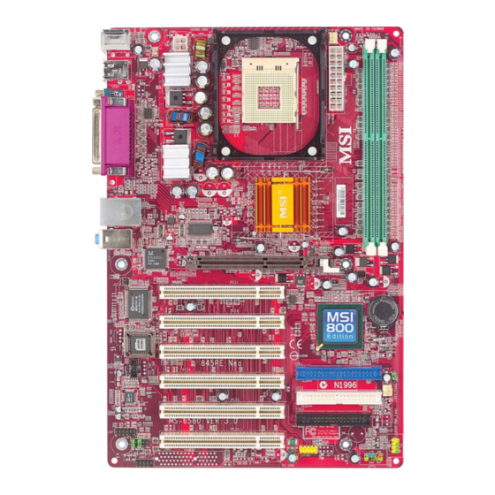
Page 11: Mainboard Layout
PCI Slot 1 Winbond W83627HF-AW PCI Slot 2 BATT ICH 4 PCI Slot 3 IDE 1 PCI Slot 4 JBAT1 CD_IN1 SYS_FAN1 IDE 2 Codec PCI Slot 5 JSP1 PCI Slot 6 FDD1 JUSB1 JFP2 JAUD1 JFP1 JDB1 MS-6580 v3.X ATX Mainboard... -
Page 12: Msi Special Features
Getting Started MSI Special Features PC Alert™ 4 The PC Alert 4 is a utility you can find in the CD-ROM disk. The utility is just like your PC doctor that can detect the following PC hardware status during real time operation: monitor CPU &... -
Page 13: Fuzzy Logic 4
After rebooting, click Turbo to apply the test result. Click Default to restore the default values. Features: MSI Logo links to the MSI Web site CPU Speed allows users to adjust the CPU speed through CPU Multiplier and FSB... -
Page 14: Live Monitor
Live Monitor™ The Live Monitor™ is a tool used to schedule the search for the latest BIOS/drivers version on the MSI Web site. To use the function, you need to install the “MSI Live Update 2” application. After the installation, the “MSI Live Monitor” icon (as shown on the right) will appear on the screen. -
Page 15: D-Bracket 2 (Optional)
MS-6580 ATX Mainboard D-Bracket™ 2 (Optional) D-Bracket™ 2 is an external USB bracket integrating four Diagnostic LEDs, which use graphic signal display to help users understand their system. The LEDs provide up to 16 combinations of signals to debug the system. The 4 LEDs can debug all problems that fail the system, such as VGA, RAM or other failures. -
Page 16: Getting Started
Getting Started D-Bracket Description Processor Initialization - This will show information regarding the processor (like brand name, system bus, etc…) Testing RTC (Real Time Clock) Initializing Video Interface - This will start detecting CPU clock, checking type of video onboard. Then, detect and initialize the video adapter. BIOS Sign On - This will start showing information about logo, processor brand name, etc…. -
Page 17: Live Bios/Live Driver
BIOS/drivers online so that you don’t need to search for the correct BIOS/driver version throughout the Web site. To use the function, you need to install the “MSI Live Update 2” application. After the installation, the “MSI Live Update 2” icon (as shown on the right) will appear on the screen. -
Page 18: S-Bracket (Optional)
Getting Started S-Bracket (Optional) S-Bracket is a bracket which provides 2 SPDIF jacks for digital audio transmission and 2 analog Line-Out connectors for additional 4-channel analog audio output. With the S-Bracket, your system will be able to perform 6- channel audio operation for wonderful surround sound effect, or connect to Sony &... -
Page 19: Msi Dvd 5.1 Channel (Optional)
To play DVD with 6-channel audio output, you must configure both the MSI DVD application and the audio codec’s software utility. Otherwise, the 6- channel audio function will not work properly. For information on how to select 6-channel mode in the audio software utility, refer to Appendix. - Page 20 Getting Started 4. Click OK. For more information about MSI DVD, you can refer to the online help coming with the application. To enter the online help: 1. Click on the icon at the bottom-right corner of the control panel.
-
Page 21: Chapter 2. Hardware Setup
Hardware Setup Chapter 2. Hardware Setup Hardware Setup This chapter tells you how to install the CPU, memory modules, and expansion cards, as well as how to setup the jump- ers on the mainboard. Also, it provides the instructions on con- necting the peripheral devices, such as the mouse, keyboard, etc. -
Page 22: Quick Components Guide
MS-6580 ATX Mainboard Quick Components Guide CPU, p.2-3 CPUFAN1, p.2-17 JPW1, p.2-9 DDR DIMMs, p.2-7 PWR1, p.2-9 Back Panel I/O, p.2-10 JCI1, p.2-24 IDE1 & IDE2, p.2-16 CD_IN1, p.2-24 JBAT1, p.2-25 SYS_FAN1, p.2-17 FDD1, p.2-15 JSP1, p.2-20 JAUD1, p.2-18 JFP2, p.2-19 JFP1, p.2-19... -
Page 23: Central Processing Unit: Cpu
CPU core speed Host Clock x Core/Bus ratio 100MHz x 14 1.4 GHz MSI Reminds You... Overheating Overheating will seriously damage the CPU and system, al- ways make sure the cooling fan can work properly to protect the CPU from overheating. -
Page 24: Cpu Installation Procedures For Socket 478
MS-6580 ATX Mainboard CPU Installation Procedures for Socket 478 Please turn off the power and unplug the power cord before Open Lever installing the CPU. Pull the lever sideways away Sliding 90 degree Plate from the socket. Make sure to raise the lever up to a 90- degree angle. -
Page 25: Installing The Cpu Fan
Hardware Setup Installing the CPU Fan As processor technology pushes to faster speeds and higher performance, thermal management becomes increasingly important. To dissipate heat, you need to attach the CPU cooling fan and heatsink on top of the CPU. Follow the instructions below to install the Heatsink/Fan: Locate the CPU and its retention Position the heatsink onto the reten-... - Page 26 MS-6580 ATX Mainboard C o nnect th e f a n p o w e r ca b le f r om th e m o unted f a n to th e 3- p i n f a n p o w e r connector on th e boa r d.
-
Page 27: Memory
Hardware Setup Memory The mainboard provides 2 slots for 184-pin DDR SDRAM DIMM (Double In-Line Memory Module) modules and supports the memory size up to 2GB. You can install PC3200/DDR400, PC2700/DDR333, PC2100/ DDR266 or PC1600/DDR200 modules on the DDR DIMM slots (DDR 1~2). For more informaton on DDR400, please refer to Appendix B. -
Page 28: Dimm Module Combination
MS-6580 ATX Mainboard DIMM Module Combination Install at least one DIMM module on the slots. Memory modules can be installed on the slots in any order. You can install either single- or double- sided modules to meet your own needs. -
Page 29: Power Supply
Hardware Setup Power Supply The mainboard supports ATX power supply for the power system. Be- fore inserting the power supply connector, always make sure that all compo- nents are installed properly to ensure that no damage will be caused. ATX 20-Pin Power Connector: PWR1 This connector allows you to connect to an ATX power supply. -
Page 30: Back Panel
MS-6580 ATX Mainboard Back Panel The back panel provides the following connectors: Parallel Mouse L-in L-out Keyboard COM A Keyboard Connector ® The mainboard provides a standard PS/2 keyboard mini DIN connec- ® ® tor for attaching a PS/2 keyboard. You can plug a PS/2 keyboard directly into this connector. -
Page 31: Mouse Connector
Hardware Setup Mouse Connector ® The mainboard provides a standard PS/2 mouse mini DIN connector ® ® for attaching a PS/2 mouse. You can plug a PS/2 mouse directly into this connector. The connector location and pin assignments are as follows: Pin Definition SIGNAL DESCRIPTION... -
Page 32: Lan Jack (Optional)
MS-6580 ATX Mainboard RJ-45 LAN Jack (Optional) The mainboard provides a RJ-45 connector that allows your computer to be connected to a network environment. Signal Description Activity Transmit differential pair Transmit differential pair Indicators Receive differential pair Not used Not used... -
Page 33: Parallel Port Connector
Hardware Setup Parallel Port Connector The mainboard provides a 25-pin female centronic connector as LPT. A parallel port is a standard printer port that supports Enhanced Parallel Port (EPP) and Extended Capabilities Parallel Port (ECP) mode. Pin Definition SIGNAL DESCRIPTION STROBE Strobe DATA0... -
Page 34: Audio Port Connectors
MS-6580 ATX Mainboard Audio Port Connectors Line Out is a connector for Speakers or Headphones. Line In is used for external CD player, Tape player, or other audio devices. Mic is a connector for microphones. Line In 1/8” Stereo Audio Connectors... -
Page 35: Connectors
Hardware Setup Connectors The mainboard provides connectors to connect to FDD, IDE HDD, case, modem, LAN, USB Ports, IR module and CPU/System FAN. Floppy Disk Drive Connector: FDD1 The mainboard provides a standard floppy disk drive connector that supports 360K, 720K, 1.2M, 1.44M and 2.88M floppy disk types. FDD1 2-15... -
Page 36: Hard Disk Connectors: Ide1 & Ide2
MS-6580 ATX Mainboard Hard Disk Connectors: IDE1 & IDE2 The mainboard has a 32-bit Enhanced PCI IDE and Ultra ATA66/100 controller that provides PIO mode 0~4, Bus Master, and Ultra ATA66/100 function. You can connect up to four hard disk drives, CD-ROM, 120MB Floppy (reserved for future BIOS) and other devices. -
Page 37: Fan Power Connectors: Cpufan1/Sys_Fan1
CPUFAN1 +12V SENSOR SYS_FAN1 MSI Reminds You... 1. Always consult the vendors for proper CPU cooling fan. 2. CPUFAN1 supports the fan control. You can install the PC Alert utility that will automatically control the CPU fan speed according to the actual CPU temperature. -
Page 38: Front Panel Audio Connector: Jaud1
MS-6580 ATX Mainboard Front Panel Audio Connector: JAUD1 You can connect an optional audio connector to the JAUD1 front panel ® audio connector. JAUD1 is compliant to Intel Front Panel I/O Connectivity Design Guide. JAUD1 Pin Definition SIGNAL DESCRIPTION AUD_MIC... -
Page 39: Front Panel Connectors: Jfp1 & Jfp2
Hardware Setup Front Panel Connectors: JFP1 & JFP2 The mainboard provides two front panel connectors for establishing elec- trical connection to the front panel switches and LEDs. JFP1 is compliant ® with Intel Front Panel I/O Connectivity Design Guide. JFP2 JFP1 JFP2 Pin Definition SIGNAL... -
Page 40: S-Bracket Connector: Jsp1
MS-6580 ATX Mainboard S-Bracket Connector: JSP1 The connector allows you to connect a S-Bracket for Sony & Philips Digital Interface (SPDIF). The S-Bracket offers 2 SPDIF jacks for digital audio transmission (one for optical fiber connection and the other for coaxial), and 2 analog Line-Out jacks for 4-channel audio output. - Page 41 Hardware Setup Optional S-Bracket Analog Line-Out jack Connect to JSP1 SPDIF jack (optical) SPDIF jack (coaxial) 2-21...
-
Page 42: Front Usb Connector: Jusb1
MS-6580 ATX Mainboard Front USB Connector: JUSB1 The mainboard provides one USB2.0 pinheader for users to connect to ® optional USB2.0 ports. The pinheader is compliant to Intel I/O Connectivity Design Guide. USB 2.0 technology increases data transfer rate up to a maximum through- put of 480Mbps, which is 40 times faster than USB 1.1, and is ideal for connect-... -
Page 43: D-Bracket 2 Connector: Jdb1
Hardware Setup D-Bracket™ 2 Connector: JDB1 The mainboard comes with a JDB1 connector for you to connect to D- Bracket™ 2. D-Bracket™ 2 is a USB Bracket that supports both USB1.1 & 2.0 spec. It integrates four LEDs and allows users to identify system problem through 16 various combinations of LED signals. -
Page 44: Chassis Intrusion Switch Connector: Jci1
MS-6580 ATX Mainboard Chassis Intrusion Switch Connector: JCI1 This connector is connected to a 2-pin chassis switch. If the chassis is opened, the switch will be short connected. The system will record this status and show a warning message on the screen. To clear the warning, you must enter ®... -
Page 45: Jumpers
Clear CMOS Keep CMOS JBAT1 MSI Reminds You... You can clear CMOS by shorting 2-3 pin while the system is off. Then return to 1-2 pin position. Avoid clearing the CMOS while the system is on; it will damage the mainboard. -
Page 46: Slots
MS-6580 ATX Mainboard Slots The motherboard provides one AGP slot and six 32-bit Master PCI bus slots. AGP Slot PCI Slots AGP (Accelerated Graphics Port) Slot The AGP slot allows you to insert the AGP 1.5V graphics card. AGP is an interface specification designed for the throughput demands of 3D graphics. -
Page 47: Pci Interrupt Request Routing
Hardware Setup PCI Interrupt Request Routing The IRQ, abbreviation of interrupt request line and pronounced I-R-Q, are hardware lines over which devices can send interrupt signals to the microprocessor. The “AGP/PCI/USB/LAN” IRQ pins are typically connected to the PCI bus INT A# ~ INT H# pins as follows: Order 1 Order 2 Order 3 Order 4 INT A# INT B#... -
Page 48: Chapter 3. Bios Setup
BIOS Setup Chapter 3. BIOS Setup BIOS Setup This chapter provides information on the BIOS Setup program and allows you to configure the system for optimum use. You may need to run the Setup program when: An error message appears on the screen during the system booting up, and requests you to run SETUP. -
Page 49: Entering Setup
MS-6580 ATX Mainboard Entering Setup Power on the computer and the system will start POST (Power On Self Test) process. When the message below appears on the screen, press <DEL> key to enter Setup. DEL:Setup F11:Boot Menu F12:Network boot TAB:Logo... -
Page 50: Control Keys
BIOS Setup Control Keys < > Move to the previous item < > Move to the next item < > Move to the item on the left-hand side < > Move to the item on the right-hand side <Enter> Select the item <Esc>... -
Page 51: The Main Menu
MS-6580 ATX Mainboard The Main Menu Once you enter AMIBIOS NEW SETUP UTILITY, the Main Menu will ap- pear on the screen. The Main Menu displays twelve configurable functions and two exit choices. Use arrow keys to move among the items and press <Enter>... - Page 52 BIOS Setup Integrated Peripherals Use this menu to specify your settings for integrated peripherals. PC Health Status This entry shows your PC health status. Frequency/Voltage Control Use this menu to specify your settings for frequency/voltage control. Set Supervisor Password Use this menu to set Supervisor Password. Set User Password Use this menu to set User Password.
-
Page 53: Standard Cmos Features
MS-6580 ATX Mainboard Standard CMOS Features The items inside STANDARD CMOS FEATURES menu are divided into 9 categories. Each category includes none, one or more setup items. Use the arrow keys to highlight the item you want to modify and use the <PgUp> or <PgDn>... - Page 54 When Enabled, BIOS will issue a virus warning message and beep if a write to the boot sector or the partition table of the HDD is attempted. Setting options: Disabled and Enabled. MSI Reminds You... This feature only protects the boot sector, not the whole hard disk.
-
Page 55: Advanced Bios Features
MS-6580 ATX Mainboard Advanced BIOS Features Quick Boot Setting the item to Enabled allows the system to boot within 5 seconds since it will skip some check items. Available options: Enabled, Disabled. Full Screen Logo Show This item enables you to show the company logo on the bootup screen. Set-... - Page 56 BIOS Setup 1st/2nd/3rd Boot Device The items allow you to set the sequence of boot devices where AMIBIOS attempts to load the operating system. The settings are: IDE-0 The system will boot from the first HDD. IDE-1 The system will boot from the second HDD. IDE-2 The system will boot from the third HDD.
- Page 57 MS-6580 ATX Mainboard MSI Reminds You... 1. Available settings for “1st/2nd/3rd Boot Device” vary de- pending on the bootable devices you have installed. For example, if you did not install a floppy drive, the setting “Floppy” does not show up.
- Page 58 This field is used to enable or disable the Hyper Threading function. Setting to Enabled will increase the system performance. Settings: Enabled, Disabled. MSI Reminds You... Enabling the functionality of Hyper-Threading Technology for your computer system requires ALL of the following platform Components: ®...
- Page 59 MS-6580 ATX Mainboard version supported by your operating system. To find out which version to use, consult the vendor of your operating system. Settings: 1.4, 1.1. CPU L1 & L2 Cache Cache memory is additional memory that is much faster than conventional DRAM (system memory).
-
Page 60: Advanced Chipset Features
BIOS Setup Advanced Chipset Features MSI Reminds You... Change these settings only if you are familiar with the chipset. DRAM Timing Setting Press <Enter> and the following sub-menu appears. DRAM Frequency Use this field to configure the clock frequency of the installed DRAM. - Page 61 MS-6580 ATX Mainboard the following fields automatically to be determined by BIOS based on the configurations on the SPD. Selecting Disabled allows users to con- figure these fields manually. CAS# Latency This controls the timing delay (in clock cycles) before SDRAM starts a read command after receiving it.
- Page 62 BIOS Setup AGP Aperture Size This setting controls just how much system RAM can be allocated to AGP for video purposes. The aperture is a portion of the PCI memory address range dedicated to graphics memory address space. Host cycles that hit the aperture range are forwarded to the AGP without any translation.
-
Page 63: Power Management Features
MS-6580 ATX Mainboard Power Management Features MSI Reminds You... S3-related functions described in this section are available only when your BIOS supports S3 sleep mode. IPCA Function This item is to activate the ACPI (Advanced Configuration and Power Man- agement Interface) function. If your operating system is ACPI-aware, such as Windows 98SE/2000/ME, select Yes. - Page 64 BIOS Setup energy. The information stored in memory will be used to re store the system when a “wake up” event occurs. Auto BIOS determines the best mode automatically. Re-Call VGA BIOS at S3 Resuming Selecting Enabled allows BIOS to call VGA BIOS to initialize the VGA card when system wakes up (resumes) from S3 sleep state.
- Page 65 MS-6580 ATX Mainboard FDC/LPT/COM Ports, Primary/Secondary master/Slave IDE These items specify if the BIOS will monitor the activity of the specified hardware peripheral or component. If set to Monitor, any activity de- tected on the specified hardware peripheral or component will wake up the system or prevent the system from entering the power saving modes.
- Page 66 Alarm Minute 00 ~ 59 Alarm Second 00 ~ 59 MSI Reminds You... If you have changed this setting, you must let the system boot up until it enters the operating system, before this function will work. USB Wakeup From S3 This item allows the activity of the USB device to wake up the system from S3 (Suspend to RAM) sleep state.
-
Page 67: Pnp/Pci Configurations
MS-6580 ATX Mainboard PNP/PCI Configurations This section describes configuring the PCI bus system and PnP (Plug & Play) feature. PCI, or Peripheral Component Interconnect, is a system which al- lows I/O devices to operate at speeds nearing the speed the CPU itself uses when communicating with its special components. - Page 68 BIOS Setup Init. Graphics Adaptor Priority This setting specifies which VGA card is your primary graphics adapter. Set- ting options are: PCI/AGP The system initializes the installed PCI VGA card first. If the PCI VGA card is not available, it will initialize the AGP card.
- Page 69 MS-6580 ATX Mainboard onboard I/O are configured as PCI/PnP. If all IRQs are set to ISA/EISA, and IRQ 14/15 are allocated to the onboard PCI IDE, IRQ 9 will still be available for PCI and PnP devices. Available settings: ISA/EISA, PCI/ PnP.
-
Page 70: Integrated Peripherals
BIOS Setup Integrated Peripherals USB Controller This setting is used to enable/disable the onboard USB controllers. Setting options: Enabled, Disabled. USB Legacy Support Set to All Device if you need to use a USB device in the operating system that does not support or have any USB driver installed, such as DOS and SCO Unix. - Page 71 MS-6580 ATX Mainboard Load Onboard LAN BIOS This feature gives you the option to load the onboard LAN BIOS or not. Setting options: Enabled, Disabled. AC’97 Audio Auto allows the mainboard to detect whether an audio device is used. If an audio device is detected, the onboard AC’97 (Audio Codec’97) controller...
- Page 72 BIOS Setup Parallel Port Mode This item selects the operation mode for the onboard parallel port: ECP, Normal, Bi-Dir or EPP. EPP Version The item selects the EPP version used by the parallel port if the port is set to EPP mode. Settings: 1.7, 1.9. Parallel Port IRQ When parallel port is set to Auto, the item shows Auto indicating that BIOS determines the IRQ for the parallel port automatically.
-
Page 73: Pc Health Status
MS-6580 ATX Mainboard PC Health Status This section shows the status of your CPU, fan, overall system status, etc. Monitor function is available only if there is hardware monitoring mechanism onboard. Chassis Intrusion The field enables or disables the feature of recording the chassis intrusion status and issuing a warning message if the chassis is once opened. -
Page 74: Frequency/Voltage Control
BIOS Setup Frequency/Voltage Control Use this menu to specify your settings for frequency/voltage control. Spread Spectrum When the motherboard clock generator pulses, the extreme values (spikes) of the pulses creates EMI (Electromagnetic Interference). The Spread Spectrum function reduces the EMI generated by modulating the pulses so that the spikes of the pulses are reduced to flatter curves. - Page 75 MS-6580 ATX Mainboard AGP/PCI Clock (MHz) This item allows you to select the AGP/PCI clock frequency. CPU Vcore Adjust This setting is used to enable or disable the ability to adjust CPU Vcore for overclocking purpose. Setting options: Yes, No.
-
Page 76: Set Supervisor/User Password
BIOS FEATURES menu. If the PASSWORD CHECK option is set to Always, the password is required both at boot and at entry to Setup. If set to Setup, password prompt only occurs when you try to enter Setup. MSI Reminds You... About Supervisor Password & User Password: Supervisor password: Can enter and change the settings of the setup menu. -
Page 77: Load High Performance/Bios Setup Defaults
MS-6580 ATX Mainboard Load High Performance/BIOS Setup Defaults The two options on the main menu allow users to restore all of the BIOS settings to High Performance defaults or BIOS Setup defaults. The High Per- formance Defaults are the values set by the mainboard manufacturer for the best system performance but probably will cause a stability issue. -
Page 78: Appendix A: Using 4- Or 6-Channel Audio Function
Using 4- or 6-Channel Audio Function Appendix A: Using 4- or 6-Channel Audio Function The motherboard is equipped with Realtek ALC650/655 chip, which provides support for 6-channel audio output, including 2 Front, 2 Rear, 1 Center and 1 Subwoofer channel. ALC650/655 allows the board to attach 4 or 6 speakers for better surround sound effect. -
Page 79: Installing The Audio Driver
MS-6580 ATX Mainboard Installing the Audio Driver You need to install the driver for Realtek ALC650/655 chip to function properly before you can get access to 4-/6-channel audio operations. Follow the procedures described below to install the drivers for different operating systems. -
Page 80: Using 4- Or 6-Channel Audio Function
Using 4- or 6-Channel Audio Function 3. Click Next to start installing files into the system. Click here 4. Click Finish to restart the system. Select this option Click here... - Page 81 MS-6580 ATX Mainboard Using 4- or 6-Channel Audio Function After installing the audio driver, you are able to use the 4-/6-channel audio feature now. To enable 4- or 6-channel audio operation, first connect 4 or 6 speakers to the appropriate audio connectors, and then select 4- or 6- channel audio setting in the software utility.
- Page 82 Using 4- or 6-Channel Audio Function audio devices you wish to use for audio outputs. The instructions shown on the Speaker Configuration screen may vary depending on how you set the options of No. of Speaker and Default Phonejack. To ensure proper hardware installation, connect your speakers to the correct phonejacks in accordance with the setting in software utility.
- Page 83 MS-6580 ATX Mainboard 7. On the S/PDIF-In tab, it shows the current status. Since this mainboard does not support the S/PDIF-in function, no selection is available. 8. On the S/PDIF-Out tab, you may slelect the format of SPDIF out.
- Page 84 Using 4- or 6-Channel Audio Function 9. On the Equalizer tab, you can adjust each volume of the speaker for current playing digital sound sources.
- Page 85 MS-6580 ATX Mainboard Connecting the Speakers When you have set the Multi-Channel Audio Function mode properly in the software utility, connect your speakers to the correct phone jacks in accordance with the setting in software utility. 2-Channel Mode for Stereo-Speaker Output...
- Page 86 Using 4- or 6-Channel Audio Function 4-Channel Mode for 4-Speaker Output When this mode is selected, plug the two front speakers to the Line Out connector on the back panel, and the other two rear speakers to the Line Out connector on the S-Bracket. Refer to the following diagram and caption for the function of each phone jack on the back panel and S-Bracket when 4-Channel mode is selected.
- Page 87 MS-6580 ATX Mainboard 6-Channel Mode for 6-Speaker Output When this mode is selected, plug the two front speakers to the Line Out connector on the back panel, and the other two rear speakers to the Line Out connector on the S-Bracket.
- Page 88 Using 4- or 6-Channel Audio Function Digital Audio Output When any Multi-Channel Audio Function mode is selected, you may also connect your speakers to the Optical or Coaxial SPDIF phone jack on the S-Bracket to exprience digital surround sound effect. Remove the plug from the optical SPIDF phone jack before inserting the fiber-optic cable, and read the following diagram and captions for the function of each phone jack on the S-Bracket.
-
Page 89: Using The Back Panel Only
MS-6580 ATX Mainboard Using the Back Panel only In addition to a default 2-channel analog audio output function, the audio connectors on the Back Panel also provide 4- or 6-channel analog audio output function if a proper setting is made in the software utility. - Page 90 Using 4- or 6-Channel Audio Function Connecting the Speakers When you have set the Multi-Channel Audio Function mode properly in the software utility, connect your speakers to the correct phone jacks in accordance with the setting in software utility. 2-Channel Mode for Stereo-Speaker Output Refer to the following diagram and caption for the function of each phone jack on the back panel when 2-Channel Mode is selected.
- Page 91 MS-6580 ATX Mainboard 4-Channel Mode for 4-Speaker Output The audio jacks on the back panel always provide 2-channel analog audio output function, however these audio jacks can be transformed to 4- or 6- channel analog audio jacks by selecting the corresponding multi-channel operation from No.
- Page 92 * Both Line In and MIC function are converted to Line Out function when 4- Channel Mode for 6-Speaker Output is selected. MSI Reminds You... If the Center and Subwoofer speaker exchange their audio channels when you play video or music on the computer, a converter may be required to exchange center and subwoofer audio signals.
-
Page 93: Testing The Connected Speakers
MS-6580 ATX Mainboard Testing the Connected Speakers To ensure that 4- or 6-channel audio operation works properly, you may need to test each connected speaker to make sure every speaker work properly. If any speaker fails to make sound, then check whether the cable is inserted firmly to the connector or replace the bad speakers with good ones. - Page 94 Using 4- or 6-Channel Audio Function 4. While you are testing the speakers in 6-Channel Mode, if the sound coming from the center speaker and subwoofer is swapped, you should select Swap Center/Subwoofer Output to readjust these two channels. A-17...
-
Page 95: Playing Karaok
MS-6580 ATX Mainboard Playing KaraOK The KaraOK function will automatically remove human voice (lyrics) and leave melody for you to sing the song. Note that this function applies only for 2-channel audio operation. Playing KaraOK 1. Click the audio icon from the window tray at the lower-right corner of the screen. -
Page 96: Appendix B: The Explanation For Overspecification And Overclocking On Intel 845Pe Chipset
The explanation for overspecification and overclocking Appendix B: The explanation for overspecification and ® overclocking on Intel 845PE chipset ® The default specification of Intel 845PE chipset is only able to support FSB 400/533MHz CPU and DDR 266/333 DRAM technology. However, we have spent engineering efforts to allow the overspecification and overclocking of 845PE Max under certain conditions. - Page 97 MS-6580 ATX Mainboard 2. Configure BIOS settings You also need to configure BIOS settings for overclocking. A. In the “Advanced Chipset Features”, go to the sub-menu “DRAM Timing Settings” and set the “DRAM Frequence” to “Auto”. B. In the “Frequency/Voltage Control”, set “CPU FSB Clock (MHz)” as 200,...
- Page 98 The explanation for overspecification and overclocking 3. System configuration and DDR 400/PC 3200 Qualified Memory Test List When using DDR400 memory modules, a maximum of 2 DIMMs are recommended. Please refer to the system configuration and DDR400/PC3200 DIMMs listed below for overclocking. Table 1: System Configuration System Configuration Manufacturer...
- Page 99 MS-6580 ATX Mainboard Table 2: DDR400/PC3200 Memory Test List Memory Memory R.S.T Model Size Slot Bandwidth Benchmark √ √ Infineon HYS64D16301GU-5-B 128MB √ (Infineon HYB25D256160BT-5) √ √ Nanya NT128D64SH4B1G-5 128MB √ (Nanya NT5DS16M16BT-5) √ √ A-DATA MD0M05F3G31JB1EAZ 256MB √ (Mosel V58C2256804SAT5) √...
- Page 100 The explanation for overspecification and overclocking Memory Memory R.S.T Model Size Slot Bandwidth Benchmark √ √ AL5D8A53TK1-5B 256MB √ (PSC A2S56D30ATP-5) √ √ M368L3223DTM-CC4 256MB √ (SEC K4H560838D-TCC4) √ √ M368L3223ETM-CCC 256MB √ (SEC K4H560838E-TCCC) √ TwinMos M2G9I08AFATT9F0811DDT 256MB √ (TwinMOS TMD7608F8E50B) √...
- Page 101 MS-6580 ATX Mainboard Memory Memory R.S.T Model Size Slot Bandwidth Benchmark √ √ Kingston KVR400X64C25/512 512MB √ (Winbond W942508BH-5) √ √ Micron MT16VDDT6464AG-40BC4 512MB √ (Micron MT46V32M8TG-5B C) √ √ Nanya NT512D64S8HB1G-5T 512MB √ (Nanya NT5DS32M8BT-5T) √ √ AL6D8A53TK1-5B 512MB √...