Table of Contents
Advertisement
Quick Links
C h a p t e r 1 .
Introduction
The 845 Pro (MS-6529) ATX mainboard is a high-performance
computer mainboard based on Intel
Pro (MS-6529) is designed for Intel
package that delivers a high performance and professional desktop platform
solution.
®
The Intel
sor interface, SDRAM interface, AGP interface and hub interface. It supports:
a single processor with a data transfer rate of 400MHz, SDRAM at 133MHz
operation (PC133), AGTL+ host bus with integrated termination supporting
32-bit host addressing, 1.5V AGP interface with 4x SBA/data transfer and 2x/4x
fast write capability, and 8-bit, 66MHz 4x hub interface to the Intel ICH2.
®
The Intel
multifunctional I/O Controller Hub that provides the interface to the PCI Bus
and integrates many of the functions needed in today's PC platforms. It
communicates with the host controller over a dedicated hub interface and
provides added flexibility in designing cost-effective system solutions.
This chapter includes the following topics:
Mainboard Specification
Mainboard Layout
Quick Components Guide
Key Features
MSI Special Features
82845 Memory Controller Hub (MCH) provides the proces-
82801BA (ICH2) chipset is a highly integrated
®
82845 & 82801BA chipsets. The 845
®
®
Pentium
4 processor in the 423 pin
1-1
Introduction
1
1-2
1-4
1-5
1-6
1-7
Advertisement
Table of Contents

Related Manuals for MSI 845 Pro


Summary of Contents for MSI 845 Pro
- Page 1 Introduction C h a p t e r 1 . Introduction The 845 Pro (MS-6529) ATX mainboard is a high-performance ® computer mainboard based on Intel 82845 & 82801BA chipsets. The 845 ® ® Pro (MS-6529) is designed for Intel...
-
Page 2: Mainboard Specification
Chapter 1 Mainboard Specification ® Supports Intel Pentium 4 processor (423 pin package) Supports 1.1GHz, 1.2GHz, 1.8GHz or faster Chipset ® Intel 845 chipset (593 FC-BGA) - AGP 4x/2x universal slot - Supports 100MHz FSB - Supports 400MHz Intel NetBurst micro-architecture bus ®... - Page 3 Introduction - 1 parallel port supports SPP/EPP/ECP mode - 4 USB ports (Rear * 2 / Front * 2), one for USB PC 2 PC Networking function - 1 Line-In/Line-Out/Mic-In/Game port - 1 D-Bracket™ header (Optional) Audio S/W Audio ICH2 chip integrated AC’97 2.1 Compliant Support 2/4 Channel Audio BIOS...
-
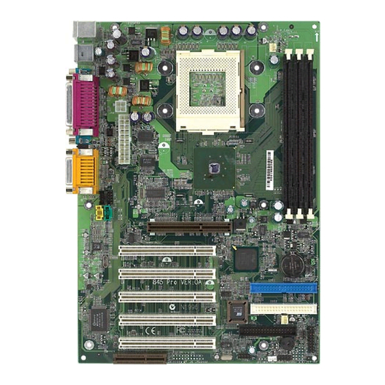
Page 4: Mainboard Layout
AGP Slot AUX_IN1 MDM_IN1 PCI Slot 1 Codec ICH 2 PCI Slot 2 BATT IDE 2 PCI Slot 3 IDE 1 PCI Slot 4 S_FAN1 F_P1 PCI Slot 5 FDD 1 JUSB1 (Optional) JMDM1 JWOL1 JGL1 845 Pro (MS-6529) ATX Mainboard... -
Page 5: Quick Components Guide
Introduction Quick Components Guide Component Function Reference DIMM1~3 Installing DIMM modules See p. 2-5~2-6 Socket 423 Installing CPU See p. 2-2~2-3 C_FAN1 Connecting to CPU FAN See p. 2-20 S_FAN1 Connecting to SYSTEM FAN See p. 2-20 ATX Power Supply Installing power supply See p. -
Page 6: Key Features
Chapter 1 Key Features ATX Form Factor ® ® CPU: Socket 423 for Intel Pentium 4 Processors Memory: 3 SDRAM DIMMs Slot: 1 AGP slot, 1 CNR slot, 5 PCI slots I/O: 2 serial ports, 1 parallel port, 4 USB 1.1 ports, 1 floppy port, 1 IrDA connector, 1 Audio/Game port PC2001 Compliant Vcore/Vio Adjustable... -
Page 7: Msi Special Features
Introduction MSI Special Features The MSI special features are designed by MSI R&D which are only available in MSI mainboards. The 845 Pro (MS-6529) mainboard is equipped with Fuzzy Logic™ III ,D-LED™, T.O.P. Tech™ III, Live BIOS™ and Live Driver™. -
Page 8: D-Led™ & D-Bracket
Chapter 1 D-LED™ & D-Bracket™ The D-LED™ uses graphic signal display to help users understand their system. Four LEDs embedded in the mainboard provide up to 16 combinations of signals to debug the system. The 4 LEDs can debug all problems that fail the system, such as VGA, RAM or other failures. - Page 9 Introduction D-LED D-Bracket Description 1 2 3 4 Processor Initialization - This will show information regarding the processor (like brand name, system bus, etc…) Testing RTC (Real Time Clock) Initializing Video Interface - This will start detecting CPU clock, checking type of video onboard.
- Page 10 Chapter 1 T.O.P Tech™ III The T.O.P Tech is a extended sensing device that can 100% accu- rately detect the CPU’s temperature. You can find out the temperature on BIOS setup menu. The PC Alert also provides the information. CPU temperaure on Setup menu AMIBIOS SETUP - Hardware Monitor Setup (C)2001 American Megatrends, Inc.
-
Page 11: Live Bios™ & Live Driver
To use the function, you need to install the “MSI Live Update Series” application. After installation, the “MSI Live Update Series” icon (as the right view) will appear on the screen. Double click the “MSI Live Update Series” icon, and the following screen will appear. -
Page 12: Chapter 2. Hardware Setup
Hardware Setup Chapter 2. Hardware Setup Hardware Setup This chapter provides you with the information about hardware setup procedures. While doing the installation, be careful in holding the compo- nents and follow the installation procedures. For some components, if you install in the wrong orientation, the components will not work properly. -
Page 13: Central Processing Unit (Cpu)
Chapter 2 Central Processing Unit: CPU ® ® The mainboard supports Intel Pentium 4 processor. The mainboard uses a CPU socket called Socket 423 for easy CPU installation. Make sure that the CPU has a Heat Sink and a cooling fan attached to prevent overheating. -
Page 14: Installing The Cpu Fan
Hardware Setup Installing the CPU Fan As processor technology pushes to faster speeds and higher performance, thermal management becomes increasingly important. To dissipate heat, you need to attach the CPU cooling fan and heatsink on top of the CPU. The Pentium 4 has its specific CPU fan. Unproper CPU fan may lead to overheating problem that will damage the CPU. -
Page 15: Cpu Core Speed Derivation Procedure
Chapter 2 CPU Core Speed Derivation Procedure CPU Clock 100MHz Core/Bus ratio then CPU core speed Host Clock x Core/Bus ratio 100MHz x 14 1.4GHz Overclocking This motherboard is designed to support overclocking. However, please make sure your components are able to WARNING! tolerate such abnormal setting, while doing overclocking. -
Page 16: Introduction To Sdram
Hardware Setup Memory The mainboard supports a maximum memory size of 3GB. It provides three 168-pin unbuffered SDRAM DIMM (Double In-Line Memory Module) sockets and supports 64MB to 1GB technology. DIMM Slots (DIMM 1~3) Introduction to SDRAM Synchronous DRAM (SDRAM) is a type of dynamic RAM memory chip that has been widely used starting in the latter part of the 1990s. -
Page 17: Dimm Modules Combination
Chapter 2 DIMM Modules Combination You can install one or more DIMM modules in the following combination: DIMM Socket Memory Module Total Memory Socket 1 64MB, 128MB, 256MB, 64MB ~ 1GB (Bank 0 & Bank 1) 512MB, 1GB Socket 2 64MB, 128MB, 256MB, 64MB ~ 1GB (Bank 2 &... -
Page 18: Power Supply
Hardware Setup Power Supply The mainboard supports ATX power supply for the power system. Before inserting the power supply connectors, always make sure that all com- ponents are installed properly to ensure that no damage will be caused. ATX 20-Pin Power Connector This connector allows you to connect to an ATX power supply. -
Page 19: Atx 12V Power Connector: Jpw1
Chapter 2 ATX 12V Power Connector: JPW1 Attaching the ATX power supply to the connector helps offering suf- ficient voltage to Pentium 4 CPU. JPW1 SIGNAL Note: We strongly recommend users to purchase and use the ATX power supply that comes with the 12V connector. Otherwise, the system might become unstable without connection of the 12V power connector after a period of time . -
Page 20: Back Panel
Hardware Setup Back Panel The Back Panel provides the following connectors: Parallel Midi/Joystick Mouse Keyboard COM A COM B L-out L-in MIC Mouse Connector ® The mainboard provides a standard PS/2 mouse mini DIN connector ® ® for attaching a PS/2 mouse. -
Page 21: Keyboard Connector
Chapter 2 Keyboard Connector ® The mainboard provides a standard PS/2 keyboard mini DIN connec- ® ® tor for attaching a PS/2 keyboard. You can plug a PS/2 keyboard directly into this connector. Pin Definition SIGNAL DESCRIPTION Keyboard DATA Keyboard DATA No connection Ground Keyboard Clock... -
Page 22: Parallel Port Connector
Hardware Setup Parallel Port Connector The mainboard provides a 25-pin female centronic connector for LPT. A parallel port is a standard printer port that supports Enhanced Parallel Port (EPP) and Extended Capabilities Parallel Port (ECP) mode. Pin Definition SIGNAL DESCRIPTION STROBE Strobe DATA0... -
Page 23: Serial Port Connectors: Com A & Com B
Chapter 2 Serial Port Connectors: COM A & COM B The mainboard has two 9-pin male DIN connectors for serial port COM A and COM B. You can attach a serial mouse or other serial devices. Pin Definition 1 2 3 4 5 SIGNAL DESCRIPTION Data Carry Detect... -
Page 24: Floppy Disk Drive Connector: Fdd1
Hardware Setup Connectors The mainboard provides connectors to connect FDD, IDE HDD, case, modem, LAN, USB Ports, IR module and CPU/System FAN. Floppy Disk Drive Connector: FDD1 The mainboard provides a standard floppy disk drive connector that supports 360KB, 720KB, 1.2MB, 1.44MB and 2.88MB floppy disk types. FDD1 2-13... -
Page 25: Hard Disk Connectors: Ide1 & Ide2
Chapter 2 Hard Disk Connectors: IDE1 & IDE2 ® The mainboard uses an IDE controller on the Intel ICH2 chipset that provides PIO mode 0-4, Bus Master, and Ultra DMA 66/100 modes. It has two HDD connectors IDE1 (Primary) and IDE2 (Secondary). You can connect up to four hard disk drives, CD-ROM or 120MB Floppy to IDE1 and IDE2. -
Page 26: Power Switch
Hardware Setup Case Connector: F_P1 The case connector block F_P1 allows you to connect to the Power Switch, Reset Switch, Speaker, Power LED, Keylock and HDD LED on the case. Keylock HDD LED Buzzer (short pin) Power Speaker Power Switch Reset Switch F_P1... - Page 27 Chapter 2 3-pin dual color power LED: Connected to pin 4, 5 & 6. The 3-pin power LED changes its color to indicate different system states: GREEN color indicates full-on mode. ORANGE color indicates suspend/sleep mode. Speaker Speaker from the system case is connected to this pin. If on-board Buzzer is available, then: Short pin 14-15: On-board Buzzer Enabled.
-
Page 28: Power Saving Led Connector: Jgl1
Hardware Setup Power Saving LED Connector: JGL1 JGL1 is connected to a power saving LED. There are two types of LED that you can use: 3-pin dual color or 2-pin dual color LED. When connected to a dual color LED, the LED light is green when system is turned on, and turns to orange color while entering the suspend/sleep state. -
Page 29: Power Saving Switch Connector: Jgs1
Chapter 2 IrDA Infrared Module Connector: IR2 This connector allows you to connect to an IrDA Infrared module. You must configure the setting through the BIOS setup to use the IR function. Signal IRRX IRTX Power Saving Switch Connector: JGS1 Attach a power saving switch to this connector. -
Page 30: Wake On Ring Connector: Jmdm1
Hardware Setup Wake On Ring Connector: JMDM1 This connector allows you to connect to a modem card with Wake On Ring function. The connector will power up the system when a signal is received through the modem card. MDM_WAKEUP 5VSB JMDM1 Note: Modem wake-up signal is active “low”. -
Page 31: Fan Power Connectors: C_Fan1/S_Fan1
Chapter 2 Fan Power Connectors: C_FAN1/S_FAN1 The C_FAN1 (processor fan) and S_FAN1 (system fan) support system cooling fan with +12V. It supports three-pin head connector. When connecting the wire to the connectors, always take note that the red wire is the positive and should be connected to the +12V, the black wire is Ground and should be connected to GND. - Page 32 Hardware Setup CD-In/Aux Line-In/Modem-In Connector: CD_IN1/ AUX_IN1/MDM_IN1 CD_IN1 connector is for CD-ROM audio connector. AUX_IN1 connector is for DVD add-on card with Line-in connector. MDM_IN1 connector is for modem with internal audio connector. CD_IN1 Mono_Out Phone_In MDM_IN1 AUX_IN1 Note: Mono_Out is connected to the Modem speaker-out connector. Phone_In is connected to the Modem Microphone-In connector.
- Page 33 Chapter 2 USB PC To PC Connector: JUSB1 (Optional) The mainboard provides one USB (Universal Serial Bus) pin header that allows you to connect optional USB ports. JUSB1 is optionally imple- mented with USB PC to PC Networking function. Depending on the model you purchased, the mainboard may offer three regular USB 1.1 ports and one USB PC2PC port, or just four regular USB 1.1 ports.
- Page 34 Hardware Setup Note: USB PC to PC Networking feature allows users to transfer and receive data from other computers or share system resources with others without using any network adapter. See below for instructions. To Attach the USB PC to PC cable Check whether the package includes the following items.
- Page 35 Chapter 2 Connect your PC to another PC via USB PC to PC cable. The transfer rate will run at USB 1.1 speed (12Mbps/s). Connect to the B Connect to the Type Connector USB 1.1 port of on your PC another PC B Type Connector For more information on USB PC to PC Networking function,...
- Page 36 Hardware Setup D-Bracket™ Connector: J2 (Optional) If your motherboard comes with the J2 connector, you can connect a D- Bracket™ to J2. D-Bracket™ is a USB Bracket integrating four LEDs whose functions are similar to D-LED™ and allows users to identify system problem through 16 various combinations of LED signals.
- Page 37 Chapter 2 D-Bracket™ with one USB PC to PC port and one regular USB port Connected to J2 Connected to JUSB1 pin header which is implemented with USB PC To PC Networking function D-Bracket™ with two regular USB ports Connected to J2 Connected to JUSB1 pin header which does NOT support USB PC To PC Networking function...
-
Page 38: Clear Cmos Jumper: Jbat1
Hardware Setup Jumpers The motherboard provides one jumper for you to set the computer’s function. This section will explain how to change your motherboard’s function through the use of the jumper. Clear CMOS Jumper: JBAT1 There is a CMOS RAM on board that has a power supply from external battery to keep the data of system configuration. -
Page 39: Agp (Accelerated Graphics Port) Slot
Chapter 2 Slots The motherboard provides five 32-bit Master PCI Bus Slots, one AGP slot, and one CNR slot. AGP Slot PCI Slots CNR Slot AGP (Accelerated Graphics Port) Slot The AGP slot allows you to insert the AGP graphics card. AGP is an interface specification designed for the throughput demands of 3D graphics. -
Page 40: Cnr (Communication Network Riser) Slot
Hardware Setup the power supply first. Meanwhile, read the documentation for the expansion card to make any necessary hardware or software settings for the expansion card, such as jumpers, switches or BIOS configuration. CNR (Communication Network Riser) Slot The CNR slot allows you to insert the CNR expansion cards. CNR is a specially designed network, audio, or modem riser card for ATX family motherboards. -
Page 41: Ami Bios Setup
® BIOS Setup Chapter 3. AMI ® BIOS Setup BIOS Setup ® ® The mainboard uses AMI BIOS ROM that provides a Setup utility for users to modify the basic system configuration. The information is stored in a battery-backed CMOS RAM so it retains the Setup information when the power is turned off. -
Page 42: Entering Setup
Chapter 3 Entering Setup Power on the computer and the system will start POST (Power On Self Test) process. When the message below appears on the screen, press <DEL> key to enter Setup. DEL:Setup F11:Boot Menu F12:Network boot TAB:Logo If the message disappears before you respond and you still wish to enter Setup, restart the system by turning it OFF and On or pressing the RESET button. -
Page 43: Control Keys
® BIOS Setup Control Keys < ↑ > Move to the previous item Move to the next item <↓> Move to the item in the left hand <←> <→> Move to the item in the right hand <Enter> Select the item <Esc>... -
Page 44: Getting Help
Chapter 3 Getting Help After entering the Setup utility, the first screen you see is the Main Menu. Main Menu The main menu displays the setup categories the BIOS supplies. You can use the arrow keys ( ↑↓ ) to select the item. The on-line description for the selected setup category is displayed on the bottom of the screen. -
Page 45: The Main Menu
® BIOS Setup The Main Menu Once you enter AMIBIOS SIMPLE SETUP UTILITY, the Main Menu will appear on the screen. The Main Menu displays twelve configurable functions and two exit choices. Use arrow keys to move among the items and press <Enter>... - Page 46 Chapter 3 PNP/PCI Configurations This entry appears if your system supports PnP/PCI. Integrated Peripherals Use this menu to specify your settings for integrated peripherals. Hardware Monitor Setup This entry shows your PC’s current status, and allows you to adjust CPU clock, core voltage etc.
-
Page 47: Standard Cmos Features
® BIOS Setup Standard CMOS Features The items inside STANDARD CMOS SETUP menu are divided into 9 categories. Each category includes none, one or more setup items. Use the arrow keys to highlight the item you want to modify and use the <PgUp> or <PgDn>... - Page 48 Chapter 3 Pri Master/Pri Slave/Sec Master/Sec Slave Press PgUp/<+> or PgDn/<-> to select the hard disk drive type. The specification of hard disk drive will show up on the right hand according to your selection. TYPE Type of the device. SIZE Capacity of the device.
-
Page 49: Advanced Bios Features
® BIOS Setup Advanced BIOS Features AMIBIOS SETUP - BIOS FEATURES SETUP (C)2001 American Megatrends, Inc. All Rights Reserved Quick Boot :Enabled 1st Boot Device :Floppy 2nd Boot Device :IDE-0 3rd Boot Device :CDROM Try Other Boot Devices :Yes Full Screen LOGO Show :Disabled S.M.A.R.T. - Page 50 Chapter 3 CDROM The system will boot from the CD-ROM. SCSI The system will boot from the SCSI. NETWORK The system will boot from the Network drive. BBS-0 The system will boot from the first BBS (BIOS Boot Specification) compliant device. BBS-1 The system will boot from the second BBS (BIOS Boot Specification) compliant device.
- Page 51 ® BIOS Setup keypad. Setting: On and Off. Swap Floppy Setting to Enabled will swap floppy drives A: and B:. Seek Floppy Setting to Enabled will make BIOS seek floppy drive A: before booting the system. Settings: Disabled and Enabled. Password Check This specifies the type of AMIBIOS password protection that is implemented.
-
Page 52: Advanced Chipset Features
Chapter 3 Advanced Chipset Features AMIBIOS SETUP - CHIPSET FEATURES SETUP (C)2001 American Megatrends, Inc. All Rights Reserved ******** DRAM Timing ***** Configure SDRAM Timing by :SPD CAS# Latency :3 Clocks RAS# Precharge :3 Clocks RAS# to CAS# Delay :3 Clocks Precharge Delay :7 Clocks DRAM Integrity Mode... - Page 53 ® BIOS Setup allowed to precharge. If insufficient time is allowed for the RAS to accumu- late its charge before DRAM refresh, refresh may be incomplete and DRAM may fail to retain data. This item applies only when synchronous DRAM is installed in the system.
-
Page 54: Power Management Setup
Chapter 3 Power Management Setup AMIBIOS SETUP - POWER MANAGEMENT SETUP (C)2001 American Megatrends, Inc. All Rights Reserved IPCA Function :Yes Mouse PowerOn Function :Disabled ACPI Standby State :S1/POS Keyboard PowerOn Function :Disabled USB Wakeup From S3 :Disabled Specific Key for PowerOn :N/A Power Management/APM :Enabled... - Page 55 ® BIOS Setup USB Wakeup From S3 This item allows the activity of the USB device to wake up the system from S3 sleep state. S3 is the STR (Suspend to RAM) mode. Available settings: Enabled and Disabled. Power Management/APM Setting to Enabled will activate the Advanced Power Management (APM) features to enhance power saving modes.
- Page 56 Chapter 3 turned off. Wake Up On Ring/LAN/PME When setting to Enabled, these features allow your system to be awakened from the power saving modes through an incoming call from the modem, a signal from the LAN, or any event on PME (Power Management Event). Settings: Enabled and Disabled.
- Page 57 ® BIOS Setup Specific Key for PowerOn If Keyboard PowerOn Function is set to Specific Key, you can assign a password for the keyboard to power on the system in the field. Power Again This item specifies whether you system will reboot after a power failure or interrupt occurs.
-
Page 58: Pnp/Pci Configurations
Chapter 3 PNP/PCI Configurations This section describes configuring the PCI bus system and PnP (Plug & Play) feature. PCI, or Personal Computer Interconnect, is a system which allows I/O devices to operate at speeds nearing the speed the CPU itself uses when communicating with its special components. - Page 59 ® BIOS Setup registers of both VGA devices to be identical. The setting must be set to Enabled if any non-standard VGA adapter card, such as MPEG card, installed in the system requires VGA palette snooping. DMA Channel 0/1/3/5/6/7 These items specify the bus that the system DMA (Direct Memory Access) channel is used.
-
Page 60: Integrated Peripherals
Chapter 3 Integrated Peripherals AMIBIOS SETUP - INTEGRATED PERIPHERALS (C)2001 American Megatrends, Inc. All Rights Reserved USB Controller :All USB Port USB Legacy Support :Disabled On-Chip IDE :Both AC’97 Audio :Auto AC’97 Modem :Auto Floppy Controller :Enabled Serial Port A :Auto Serial Port B :Auto... - Page 61 ® BIOS Setup will be enabled; if not, the controller is disabled. Disable the function if you want to use other controller cards to connect an audio device. Settings: Disabled and Auto. AC’97 Modem This item is used to enable or disable the onboard MC’97 (Modem Codec’97) feature.
- Page 62 Chapter 3 IR Pin Select Set to IRRX/IRTX when using an internal IR module connected to the IR (IR2) connector. Set to SINB/SOUTB. when connecting an IR adapter to COM B. Parallel Port This field specifies the base I/O port address of the onboard parallel port. Selecting Auto allows AMIBIOS to automatically determine the correct base I/O port address.
- Page 63 ® BIOS Setup Settings: Disabled, 200 and 208. 3-23...
-
Page 64: Hardware Monitor Setup
Chapter 3 Hardware Monitor Setup This section describes how to set the CPU FSB frequency, monitor the current hardware status including CPU/system temperatures, CPU/System Fan speeds, Vcore etc. Monitor function is available only if there is hard- ware monitoring mechanism onboard. AMIBIOS SETUP - Hardware Monitor Setup (C)2001 American Megatrends, Inc. - Page 65 ® BIOS Setup overclocking the processor. CPU Vcore Adjust The item is used to enable or disable the CPU Vcore Adjust function. The item enables you to overclock the processor. Settings: No and Yes. CPU Vcore The item is used to adjust the CPU core voltage (Vcore). DRAM Voltage Adjust Use the field to select the appropriate DRAM voltage.
-
Page 66: Load High Performance/Bios Setup Defaults
Chapter 3 Load High Performance/BIOS Setup Defaults The two options on the main menu allow users to restore all of the BIOS settings to the default High Performance or BIOS Setup defaults. The High Performance defaults are the default values set by the mainboard manufac- turer for the best system performance but probably will cause a stability issue. - Page 67 ® BIOS Setup When you select Load BIOS Setup Defaults, a message as below appears: AMIBIOS SIMPLE SETUP UTILITY - VERSION 1.45 (C)2001 American Megatrends, Inc. All Rights Reserved Standard CMOS Features Load High Performance Defaults Advanced BIOS Features Load BIOS Setup Defaults Supervisor Password Advanced Chipset Features User Password...
-
Page 68: Supervisor/User Password
Chapter 3 Supervisor/User Password When you select this function, a message as below will appear on the screen: AMIBIOS SIMPLE SETUP UTILITY - VERSION 1.45 (C)2001 American Megatrends, Inc. All Rights Reserved Load High Performance Defaults Standard CMOS Features Advanced BIOS Features Load BIOS Setup Defaults Supervisor Password Advanced Chipset Features... - Page 69 ® BIOS Setup Additionally, when a password is enabled, you can also have AMIBIOS to request a password each time the system is booted. This would prevent unauthorized use of your computer. The setting to determine when the pass- word prompt is required is the PASSWORD CHECK option of the ADVANCED BIOS FEATURES menu.
-
Page 70: Ide Hdd Auto Detection
Chapter 3 IDE HDD AUTO Detection You can use this utility to AUTOMATICALLY detect the characteristics of most hard drives. AMIBIOS SETUP - STANDARD CMOS SETUP (C)2001 American Megatrends, Inc. All Rights Reserved Date (mm/dd/yyyy) : Mon Jul 02, 2001 Time (hh/mm/ss) : 00:00:00 TYPE... -
Page 71: Save And Exit Setup
® BIOS Setup Save & Exit Setup When you want to quit the Setup menu, you can select this option to save the changes and quit. A message as below will appear on the screen. AMIBIOS SIMPLE SETUP UTILITY - VERSION 1.45 (C)2001 American Megatrends, Inc. -
Page 72: Exit Without Saving
Chapter 3 Exit Without Saving When you want to quit the Setup menu, you can select this option to abandon the changes. A message as below will appear on the screen. AMIBIOS SIMPLE SETUP UTILITY - VERSION 1.45 (C)2001 American Megatrends, Inc. All Rights Reserved Standard CMOS Features Load High Performance Defaults Load BIOS Setup Defaults... -
Page 73: Appendix A. Usb Pc To Pc Net
USB PC to PC Networking Function Appendix A. USB PC to PC Net- working Function USB PC to PC Networking Function USB PC to PC is the best solution for providing the easiest network connection service to you. By connecting multiple PCs through USB PC to PC port, you can build up a local area network without any network adapter. -
Page 74: Installing Genelink™ Lan Driver
Appendix A Installing GeneLink™ LAN Driver Before you use the function, you need to install the GeneLink™ LAN Driver to all PCs connected via USB PC to PC cables. Step 1. Installing driver 1. Insert the driver CD and click “USB PC to PC” button to install the driver. 2. - Page 75 USB PC to PC Networking Function Notice: 1. You should use the same network protocol (TCP/IP, NetBEUI or IPX) for connecting GeneLink LAN to existing Home/Office LAN. 2. If you’ve already configured your [IPX/SPX] and [Client for Netware Networks] before installing GeneLink driver, we strongly recommend that you should also install Software Router while installing GeneLink...
-
Page 76: Using Usb Pc To Pc Networking Function
Appendix A Using USB PC to PC Networking Function How to share your files, folders, drives and printers Go to the file, folder, drive or printer that you want to share. Right click your mouse pointer on the resource you want to share, you’ll see a POP-UP Menu. - Page 77 USB PC to PC Networking Function In “Sharing” tag, select “Share As”. Enter a name to help others recognize your sharing file or device (optional). Select “Access Type”. If you select “ Depend on Password”, your need to assign an access password for this device. Click “OK”...
- Page 78 Appendix A Connecting to Internet through USB PC to PC & Office/Home LAN If you would like to access Internet resources through USB PC to PC, here are some things you should notice: You must define which computer should install GeneLink Software Router.
- Page 79 USB PC to PC Networking Function - Click on “Properties”, you’ll see another menu. - Choose TCP/IP in Configuration tag, and then press “Proper- ties” button. You’ll see “TCP/IP Properties” menu.
- Page 80 Appendix A - Now you need to navigate between “IP Address”, “Gateway”, and “DNS Configuration” tags to specify “IP Address”, “Subnet Mask”, “Gateway” and “DNS Server”. If you don’t know their values, pleases consult your Network Administrator. - Press “OK” button to go back to “Network” pop-up menu. Choose “Identification”...
- Page 81 USB PC to PC Networking Function SPECIAL NOTICE for those users who have already installed Network Adapter in their system: If you’ve already configured your [IPX/SPX] and [Client for Netware Networks] before installing GeneLink driver, we strongly recommend that you should also install Software Router when you install GeneLink driver into your system.
- Page 82 Appendix A Connecting to internet through USB PC to PC & remote modem If there is no existing Office/Home LAN and your computer does not have a modem, you still can connect USB PC to PC to internet through another computer with a modem installed.
- Page 83 USB PC to PC Networking Function “Communications”. The “Communications” window appears. Check “Internet Connection Sharing” and click “OK”. The “Home Networking Wizard” starts. Click “Next”. A-11...
- Page 84 Appendix A Click “Adirect connection to my ISP using the following device”, and select “GeneLink Network Adapter” from the pull- down menu. Click “Next”. Note: For the computer with a modem installed, you need to select “My Connection” instead of “GeneLink Network Adapter”...
- Page 85 USB PC to PC Networking Function Click “Finish.” Restart the computer. Note: In Windows® 98SE, you can access internet through the shared connection of another computer, but it is unable for you to control the remote modem. However, in Windows® ME, you are allowed to dial the remote modem of another computer using the dialing program built in Windows®.