
Related Manuals for MSI 645E Max-U


Summary of Contents for MSI 645E Max-U
- Page 1 645E Max-U MICRO-STAR INTERNATIONAL MS-6547 (v2.1) ATX Mainboard Version 2.2 G52-MA00646...
- Page 2 Manual Rev: 2.2 Release Date: July 2002 FCC-B Radio Frequency Interference Statement This equipment has been tested and found to comply with the limits for a class B digital device, pursuant to part 15 of the FCC rules. These limits are designed to provide reasonable protection against harmful interference when the equip- ment is operated in a commercial environment.
- Page 3 Edition July 2002 Copyright Notice The material in this document is the intellectual property of MICRO-STAR INTERNATIONAL. We take every care in the preparation of this document, but no guarantee is given as to the correctness of its contents. Our products are under continual improvement and we reserve the right to make changes without notice.
- Page 4 Safety Instructions Read the safety instructions carefully. Save this User’s Guide for possible use later. Keep this equipment away from humidity. Lay this equipment on a stable and flat surface before setting it up. The openings on the enclosure are used for air convection and to prevent the equipment from overheating.
-
Page 5: Table Of Contents
Chapter 1. Getting Started ................ 1-1 Mainboard Specification ..............1-2 Mainboard Layout ................1-4 Quick Components Guide ..............1-5 MSI Special Features ................1-6 Fuzzy Logic™ 4 ................1-6 Live BIOS™/Live Driver™ ............1-7 D-Bracket™ 2 ................1-8 PC Alert™ III ................1-10 Chapter 2. - Page 6 Connectors ..................2-12 Floppy Disk Drive Connector: FDD1 ........... 2-12 Hard Disk Connectors: IDE1 & IDE2 ........... 2-13 Fan Power Connectors: CPUFA/SYSFA ........2-14 Front Panel Connector: JFP1 & JFP2 ........... 2-15 Front Panel Audio Connector: JAUD1 ........2-16 D-Bracket™ 2 Connector: JLED1 ..........2-17 Front USB Connectors: JUSB1 &...
- Page 7 Integrated Peripherals ................ 3-21 PC Health Status ................3-25 Frequency/Voltage Control ..............3-26 Set Supervisor/User Password ............3-28 Load Optimal/High Performance Defaults .......... 3-29 Appendix: Using 4- or 6-Channel Audio Function ........A-1 Installing the Audio Driver ..............A-2 Installation for Windows 98SE/ME/2000/XP ........ A-2 Using 4- or 6-Channel Audio Function ..........
-
Page 8: Chapter 1. Getting Started
Chapter 1. Getting Started Getting Started Thank you for purchasing the 645E Max-U (MS-6547 v2.1) ATX mainboard. The 645E Max-U is a superior computer mainboard based on 645DX & SiS 962L chipsets for optimal system efficiency. Designed to fit ®... -
Page 9: Mainboard Specification
Chapter 1 Mainboard Specification Support Socket 478 for Intel Pentium 4 processors (Williamette- and ® ® Northwood-core) Support FSB at 400/533MHz (100/133MHz QDR) Core Frequency 533MHz from 1.3GHz to 2.53GHz Chipset 645DX Chipset NB ® - Support 64 bit P4 processors at 533MHz - Support 32 bit AGP 4x/2x slot - Support 64 bit high performance DDR333/DDR266 memory controller - Support bi-directional 16 bit data bus with 533MHz bandwidth MuTIOL... - Page 10 Getting Started On-Board Peripherals On-Board Peripherals include: - 1 floppy port supports 2 FDDs with 360K, 720K, 1.2M, 1.44M and 2.88Mbytes - 2 serial ports (COM A + COM B) - 1 parallel port supports Normal/Bi-Dir/EPP/ECP mode - 2 USB ports (USB 2.0 Controller by SiS 962L SB) ®...
-
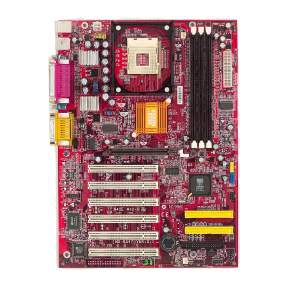
Page 11: Mainboard Layout
PCI Slot 1 JUSB2 962L PCI Slot 2 JSP1 JBT1 IDE 1 PCI Slot 3 IDE 2 PCI Slot 4 Winbond W83697HF FDD 1 BATT PCI Slot 5 JFP2 BIOS JIR1 SYSFA JAUD1 JBAT1 JLED1 JFP1 645E Max-U (MS-6547 v2.X) ATX Mainboard... -
Page 12: Quick Components Guide
Getting Started Quick Components Guide Component Function Reference CONN1/JPW1 ATX power connectors See p. 2-7 JKBMS1 Mouse connector See p. 2-8 JKBMS1 Keyboard connector See p. 2-9 USB Connectors Connecting to USB devices See p. 2-9 COM A & COM B Serial port connectors See p. -
Page 13: Msi Special Features
After rebooting, click Turbo to apply the test result. Click Default to restore the default values. Features: MSI Logo links to the MSI Web site CPU Speed allows users to adjust the CPU speed through CPU Multiplier and FSB... -
Page 14: Live Bios™/Live Driver
Web site. To use the function, you need to install the “MSI Live Update Series 2” application. After the installation, the “MSI Live Update Series 2” icon (as shown on the right) will appear on the screen. Double click the “MSI Live Update Series 2” icon, and the following screen will appear: Five buttons are placed on the leftmost pane of the screen. -
Page 15: D-Bracket™ 2
Chapter 1 D-Bracket™ 2 (Optional) D-Bracket™ 2 is a USB bracket integrating four Diagnostic LEDs, which use graphic signal display to help users understand their system. The LEDs provide up to 16 combinations of signals to debug the system. The 4 LEDs can detect all problems that fail the system, such as VGA, RAM or other failures. - Page 16 Getting Started D-Bracket™ 2 Description Processor Initialization - This will show information regarding the processor (like brand name, system bus, etc…) Testing RTC (Real Time Clock) Initializing Video Interface - This will start detecting CPU clock, checking type of video onboard.
-
Page 17: Pc Alert™ Iii
Chapter 1 PC Alert™ III The PC Alert III is an utility you can find in the CD-ROM disk. The utility is just like your PC doctor that can detect the following PC hardware status during real time operation: * monitor CPU & system temperatures * monitor fan speed(s) * monitor system voltage * monitor chassis intrusion... -
Page 18: Chapter 2. Hardware Setup
Hardware Setup Chapter 2. Hardware Setup Hardware Setup This chapter provides you with the information about hardware setup procedures. While doing the installation, be careful in holding the components and follow the installation procedures. For some components, if you install in the wrong orientation, the components will not work properly. -
Page 19: Central Processing Unit: Cpu
Chapter 2 Central Processing Unit: CPU ® ® The mainboard supports Intel Pentium 4 processor in the 478 pin package. The mainboard uses a CPU socket called PGA478 for easy CPU installation. When you are installing the CPU, make sure the CPU has a heat sink and a cooling fan attached on the top to prevent overheating. -
Page 20: Installing The Cpu Fan
Hardware Setup Installing the CPU Fan As processor technology pushes to faster speeds and higher performance, thermal management becomes increasingly important. To dissi- pate heat, you need to attach the CPU cooling fan and heatsink on top of the CPU. Follow the instructions below to install the Heatsink/Fan: 1. -
Page 21: Cpu Core Speed Derivation Procedure
Chapter 2 5. Connect the fan power cable from the mounted fan to the 3-pin fan power connector on the board. fan power cable CPU Core Speed Derivation Procedure CPU Clock 100MHz Core/Bus ratio then CPU core speed Host Clock x Core/Bus ratio 100MHz x 14 1.4GHz Overclocking... -
Page 22: Memory
Hardware Setup Memory The mainboard provides 3 slots for 184-pin, 2.5V DDR DIMM with 6 memory banks. You can install PC1600/PC2100/PC2700 DDR SDRAM modules on the DDR DIMM slots (DDR 1~3). To operate properly, at least one DIMM module must be installed. DDR DIMM Slots (DDR 1~3) Introduction to DDR SDRAM... -
Page 23: Ddr Module Combination
Chapter 2 DDR Module Combination You can install either single-sided or double-sided 184-pin DDR DIMM modules into DDR DIMM slots to meet your needs. Different from the SDR DIMM, the DDR DIMM has only one notch on the center of module. The module will only fit in the right orientation. -
Page 24: Power Supply
Hardware Setup Power Supply The mainboard supports ATX power supply for the power system. Be- fore inserting the power supply connector, always make sure that all compo- nents are installed properly to ensure that no damage will be caused. ATX 20-Pin Power Connector: CONN1 This connector allows you to connect to an ATX power supply. -
Page 25: Back Panel
Chapter 2 Back Panel The Back Panel provides the following connectors: Parallel Midi/Joystick Mouse Keyboard USB COM A COM B L-out L-in MIC Mouse Connector: JKBMS1 ® The mainboard provides a standard PS/2 mouse mini DIN connector for ® ® attaching a PS/2 mouse. -
Page 26: Keyboard Connector: Jkbms1
Hardware Setup Keyboard Connector: JKBMS1 ® The mainboard provides a standard PS/2 keyboard mini DIN connector ® ® for attaching a PS/2 keyboard. You can plug a PS/2 keyboard directly into this connector. Pin Definition SIGNAL DESCRIPTION Keyboard DATA Keyboard DATA No connection Ground Keyboard Clock... -
Page 27: Serial Port Connector: Com A & Com B
Chapter 2 Serial Port Connector: COM A & COM B The mainboard offers two 9-pin male DIN connectors for serial port COM A and COM B. The ports are 16550A high speed communication ports that send/receive 16 bytes FIFOs. You can attach a serial mouse or other serial devices directly to them. -
Page 28: Parallel Port Connector: Lpt1
Hardware Setup Parallel Port Connector: LPT1 The mainboard provides a 25-pin female centronic connector for LPT. A parallel port is a standard printer port that supports Enhanced Parallel Port (EPP) and Extended Capabilities Parallel Port (ECP) mode. Pin Definition SIGNAL DESCRIPTION STROBE Strobe... -
Page 29: Connectors
Chapter 2 Connectors The mainboard provides connectors to connect to FDD, IDE HDD, case, modem, LAN, USB Ports, IR module and CPU/System FAN. Floppy Disk Drive Connector: FDD1 The mainboard provides a standard floppy disk drive connector that supports 360K, 720K, 1.2M, 1.44M and 2.88M floppy disk types. FDD 1 2-12... -
Page 30: Hard Disk Connectors: Ide1 & Ide2
Hardware Setup ATA133 Hard Disk Connectors: IDE1 & IDE2 The mainboard has a 32-bit Enhanced PCI IDE and Ultra DMA 33/66/100/ 133 controller that provides PIO mode 0~4, Bus Master, and Ultra DMA 33/66/ 100/133 function. You can connect up to four hard disk drives, CD-ROM, 120MB Floppy (reserved for future BIOS) and other devices. -
Page 31: Fan Power Connectors: Cpufa/Sysfa
Chapter 2 Fan Power Connectors: CPUFA/SYSFA The CPUFA (processor fan) and SYSFA (system fan) support system cooling fan with +12V. It supports three-pin head connector. When connect- ing the wire to the connectors, always take note that the red wire is the positive and should be connected to the +12V, the black wire is Ground and should be connected to GND. -
Page 32: Front Panel Connector: Jfp1 & Jfp2
Hardware Setup Front Panel Connector: JFP1 & JFP2 The mainboard provides two front panel connectors for electrical con- nection to the front panel switches and LEDs. JFP1 and JFP2 are compliant ® with Intel Front Panel I/O Connectivity Design Guide. JFP2 (Intel spec) JFP1... -
Page 33: Front Panel Audio Connector: Jaud1
Chapter 2 Front Panel Audio Connector: JAUD1 The front panel audio connector, JAUD1, allows you to connect to the ® front panel audio and is compliant with Intel Front Panel I/O Connectivity Design Guide. JAUD1 Pin Definition SIGNAL DESCRIPTION AUD_MIC Front panel microphone input signal AUD_GND Ground used by analog audio circuits... -
Page 34: D-Bracket™ 2 Connector: Jled1
Hardware Setup D-Bracket™ 2 Connector: JLED1 The mainboard comes with a JLED1 connector for you to connect to D- Bracket™ 2. D-Bracket™ 2 is a USB Bracket that supports both USB1.1 & 2.0 spec. It integrates four LEDs and allows users to identify system problem through 16 various combinations of LED signals. -
Page 35: Front Usb Connectors: Jusb1 & Jusb2
Chapter 2 Front USB Connectors: JUSB1/2 The mainboard provides two USB2.0 pinheaders for users to connect to ® optional USB2.0 ports. These pinheaders are compliant to Intel I/O Connec- tivity Design Guide. USB 2.0 technology increases data transfer rate up to a maximum through- put of 480Mbps, which is 40 times faster than USB 1.1, and is ideal for connect- ing high-speed USB interface peripherals such as USB HDD, digital cameras, MP3 players, printers, modems and the like. - Page 36 Hardware Setup To Attach the Optional USB 2.0 Ports: 1. Take out the USB 2.0 bracket and D-Bracket™ 2 (if there is any). 2. Locate the blue USB pinheader (JUSB2) and yellow USB pinheader (JUSB1) on the motherboard. 3. Connect the USB 2.0 bracket to blue USB pinheader, and D-Bracket™ 2 to yellow USB pinheader.
-
Page 37: Bluetooth Connector: Jbt1
Chapter 2 Bluetooth Connector: JBT1 This connector is used to connect a bluetooth module for wireless connection. JBT1 JBT1 Pin Definition SIGNAL SIGNAL 5VDUAL 3VDUAL D+ (USB signal) D- (USB signal) Note: 1. Because the bluetooth connector shares the USB interface with blue-colored USB2.0 connector, the left USB2.0 port will not func- tion when you attach a bluetooth module to this connector. -
Page 38: S-Bracket Connector: Jsp1
Hardware Setup S-Bracket Connector: JSP1 The connector allows you to connect a S-Bracket for Sony & Philips Digital Interface (SPDIF). The S-Bracket offers 2 SPDIF jacks for digital audio transmission (one for optical fiber connection and the other for coaxial), and 2 analog Line-Out jacks for 4-channel audio output. -
Page 39: Cd-In Connector: Jcd1
Chapter 2 CD-In Connector: JCD1 The connector is for CD-ROM audio connector. JCD1 IrDA Infrared Module Header: JIR1 This connector allows you to connect to IrDA Infrared modules. You must configure the setting through the BIOS setup to use the IR function. JIR1 ®... -
Page 40: Jumpers
Hardware Setup Jumpers The motherboard provides one jumper for you to set the computer’s function. This section will explain how to change your motherboard’s function through the use of the jumper. Clear CMOS Jumper: JBAT1 There is a CMOS RAM on board that has a power supply from external battery to keep the data of system configuration. -
Page 41: Slots
Chapter 2 Slots The motherboard provides six 32-bit Master PCI bus slots and one AGP slot. AGP Slot PCI Slots AGP (Accelerated Graphics Port) Slot The AGP slot allows you to insert the AGP graphics card. AGP is an interface specification designed for the throughput demands of 3D graphics. It introduces a 66MHz, 32-bit channel for the graphics controller to directly access main memory and provides three levels of throughputs: 1x (266Mbps), 2x (533Mbps) and 4x (1.07Gbps). -
Page 42: Pci Interrupt Request Routing
Hardware Setup PCI Interrupt Request Routing The IRQ, abbreviation of interrupt request line and pronounced I-R-Q, are hardware lines over which devices can send interrupt signals to the microprocessor. The PCI IRQ pins are typically connected to the PCI bus INT A# ~ INT D# pins as follows: Order 1 Order 2... -
Page 43: Chapter 3. Bios Setup
BIOS Setup ® ® Chapter 3. AMI BIOS Setup ® BIOS Setup ® This chapter provides information on the AMI BIOS Setup program and al- lows you to configure the system for optimum use. You may need to run the Setup program when: An error message appears on the screen during the system booting up, and requests you to run SETUP. -
Page 44: Entering Setup
Chapter 3 Entering Setup Power on the computer and the system will start POST (Power On Self Test) process. When the message below appears on the screen, press <DEL> key to enter Setup. DEL:Setup F11:Boot Menu F12:Network boot TAB:Logo If the message disappears before you respond and you still wish to enter Setup, restart the system by turning it OFF and On or pressing the RESET button. -
Page 45: Control Keys
BIOS Setup ® Control Keys <↑> Move to the previous item <↓> Move to the next item Move to the item in the left hand <←> <→> Move to the item in the right hand <Enter> Select the item <Esc> Jumps to the Exit menu or returns to the main menu from a submenu <+/PU>... -
Page 46: The Main Menu
Chapter 3 The Main Menu Once you enter AMIBIOS NEW SETUP UTILITY, the Main Menu will appear on the screen. The Main Menu displays twelve configurable functions and two exit choices. Use arrow keys to move among the items and press <Enter> to enter the sub-menu. - Page 47 BIOS Setup ® PNP/PCI Configurations This entry appears if your system supports PnP/PCI. Integrated Peripherals Use this menu to specify your settings for integrated peripherals. PC Health Status Use this menu to show the current status of your PC, such as temperature, Vcore, and other settings.
-
Page 48: Standard Cmos Features
Chapter 3 Standard CMOS Features The items inside STANDARD CMOS SETUP menu are divided into 9 catego- ries. Each category includes none, one or more setup items. Use the arrow keys to highlight the item you want to modify and use the <PgUp> or <PgDn> keys to switch to the value you prefer. - Page 49 BIOS Setup ® Pri Master/Pri Slave/Sec Master/Sec Slave Press PgUp/<+> or PgDn/<-> to select the hard disk drive type. The specifica- tion of hard disk drive will show up on the right hand according to your selection. Type Select how to define the HDD parameters Cylinders Enter cylinder number Heads...
-
Page 50: Advanced Bios Features
Chapter 3 Advanced BIOS Features Quick Boot Setting the item to Enabled allows the system to boot within 5 seconds since it will skip some check items. Available options: Enabled and Disabled. Full Screen Logo Show This item enables you to show the company logo on the bootup screen. Set- tings are: Silent Shows the POST messages at boot. - Page 51 BIOS Setup ® Boot Device Priority The items allow you to set the sequence of boot devices where AMIBIOS attempts to load the operating system. The settings are: Disabled Disable this sequence. IDE-0 The system will boot from the first HDD. IDE-1 The system will boot from the second HDD.
- Page 52 Chapter 3 Note: Available settings for “Boot Device Priority” vary depending on the bootable devices you have installed. For example, if you did not install a floppy drive, the setting “Floppy” does not show up. Try Other Boot Devices Setting the option to Yes allows the system to try to boot from other devices if the system fails to boot from the 1st/2nd/3rd boot device.
- Page 53 BIOS Setup ® Internal/External Cache Cache memory is additional memory that is much faster than conventional DRAM (system memory). When the CPU requests data, the system transfers the requested data from the main DRAM into cache memory, for even faster access by the CPU.
-
Page 54: Advanced Chipset Features
Chapter 3 Advanced Chipset Features Note: Change these settings only if you are familiar with the chipset. AGP Aperture Size The field selects the size of the Accelerated Graphics Port (AGP) aperture. Aperture is a portion of the PCI memory address range dedicated for graphics memory address space. - Page 55 BIOS Setup ® Timing Setting Mode The DRAM timing is controlled by the DRAM Timing Registers. The Timings programmed into this register are dependent on the system design. Slower rates may be required in certain system designs to support loose layouts or slower memory.
- Page 56 Chapter 3 Power Management Features Power Button Function This feature sets the function of the power button. Settings are: Power Off The power button functions as normal on/off button. Suspend When you press the power button, the computer enters the suspend/sleep mode, but if the button is pressed for more than four seconds, the computer is turned off.
-
Page 57: Power Management Setup
BIOS Setup ® S1/POS The S1 sleep mode is a low power state. In this state, no system context is lost (CPU or chipset) and hardware maintains all system context. S3/STR The S3 sleep mode is a lower power state where the infor- mation of system cofiguration and open applications/ files is saved to main memory that remains powered while most other hardware components turn off to save energy. - Page 58 Chapter 3 Set Wake Up Events Press <Enter> to enter the sub-menu and the following screen appears: Wake Up On Ring, Wake Up On PME#, Resume on PS2 Mouse From S3, PS2 MOUSE Wake Select Mode, USB Wakeup From S1/S3 These items specify whether the system will be awakened from power savingh modes when activity or input signal of the specified hardware peripheral or component is detected.
- Page 59 BIOS Setup ® Keyboard PowerOn From S3 The item specify how the system will be awakened from power saving mode when input signal of the keyboard is detected. If set to Specific Key, <Ctrl+Alt+BackSpace> is the only one Power On event. If set to Password, please press <Enter>...
-
Page 60: Pnp/Pci Configurations
Chapter 3 PNP/PCI Configurations This section describes configuring the PCI bus system and PnP (Plug & Play) feature. PCI, or Peripheral Component Interconnect, is a system which allows I/O devices to operate at speeds nearing the speed the CPU itself uses when communicating with its special components. - Page 61 BIOS Setup ® Allocate IRQ to PCI VGA Set to Yes allows BIOS to assign an IRQ to PCI/VGA card. Select No if you want to release the IRQ. PCI IDE BusMaster Set this option to Enabled to specify that the IDE controller on the PCI local bus has bus mastering capability.
- Page 62 Chapter 3 Set DMAs to PnP or ISA Press <Enter> to enter the sub-menu and the following screen appears: DMA Channel 0/1/3/5/6/7 These items specify the bus that the system DMA (Direct Memory Access) channel is used. The settings determine if AMIBIOS should remove a DMA from the available DMAs passed to devices that are configurable by the system BIOS.
-
Page 63: Integrated Peripherals
BIOS Setup ® Integrated Peripherals AC97 Audio Enabled allows the mainboard to detect whether an audio device is used. If the device is detected, the onboard AC’97 (Audio Codec’97) controller will be enabled; if not, it is disabled. Disable the controller if you want to use other controller cards to connect an audio device. - Page 64 Chapter 3 USB 2.0 Supports Set to Enabled if your need to use any USB 2.0 device in the operating system that does not support or have any USB 2.0 driver installed, such as DOS and SCO Unix. Setting options: Disabled, Enabled. USB Legacy Support Set to Enabled if your need to use any USB device in the operating system that does not support or have any USB driver installed.
- Page 65 BIOS Setup ® OnBoard Serial Port A/B These items specify the base I/O port addresses of the onboard Serial Port 1 (COM A)/Serial Port 2 (COM B). Selecting Auto allows AMIBIOS to automatically determine the correct base I/O port address. Settings: Auto, 3F8/COM1, 2F8/COM2, 3E8/COM3, 2E8/COM4 and Disabled.
- Page 66 Chapter 3 Parallel Port DMA Channel This feature needs to be configured only when Port Mode is set to the ECP mode. When Parallel Port is set to Auto, the field will show Auto indicating that BIOS automatically determines the DMA channel for the parallel port.
-
Page 67: Pc Health Status
BIOS Setup ® PC Health Status This section shows the status of your CPU, fan, warning for overall system status. Vcore, +3.3V, +5.0V, +12V, -12V, -5.0V, Battery Voltage, SYSTEM Fan Speed, CPU FAN Speed, SYSTEM Temperature, CPU Temperature These items display the current status of all of the monitored hardware de- vices/components such as system voltages, temperatures and fan speeds. -
Page 68: Frequency/Voltage Control
Chapter 3 Frequency/Voltage Control This section describes how to set the Chassis Intrusion feature, CPU FSB frequency, monitor the current hardwae status including CPU/system temperatures, CPU/System Fan speeds, Vcore etc. Monitor function is available only if there is hardware monitoring mechanism onboard. Detect CPU FSB Clock This setting enables you to detect the CPU Front Side Bus clock frequency. - Page 69 BIOS Setup ® CPU FSB Clock Setting Options 100MHz 1:1, 3:4, 3:5, 2:3, By SPD 101~132MHz 1:1, 3:4, 3:5, 2:3 133~160MHz 4:3, 1:1, 4:5, By SPD 161~200MHz Auto DRAM Frequency This item shows the current frequency of DDR DRAM. (read only) CPU Multiple Factory This item allows users to select the CPU multiplier value.
-
Page 70: Set Supervisor/User Password
Chapter 3 Set Supervisor/User Password When you select this function, a message as below will appear on the screen: Type the password, up to six characters in length, and press <Enter>. The password typed now will replace any previously set password from CMOS memory. -
Page 71: Load Optimal/High Performance Defaults
BIOS Setup ® Load Optimal/High Performance Defaults The two options on the main menu allow users to restore all of the BIOS settings to High Performance defaults or Optimal defaults. The High Perform- ance Defaults are the default values set by the mainboard manufacturer for the best system performance but probably will cause a stability issue. -
Page 72: Appendix: Using 4- Or 6-Channel Audio Function
Using 4- or 6-Channel Audio Function Appendix. Using 4- or 6-Channel Appendix: Using 4- or 6-Channel Audio Audio Function Function The motherboard comes with Realtek ALC650 chip, which provides support for 6-channel audio output, including 2 Front, 2 Rear, 1 Center and 1 Subwoofer channel. -
Page 73: Installing The Audio Driver
Appendix Installing the Audio Driver You need to install the driver for Realtek ALC650 chip to function prop- erly before you can get access to 4-/6-channel audio operations. Follow the procedures described below to install the drivers for different operating systems. Installation for Windows 98SE/ME/2000/XP ®... - Page 74 Using 4- or 6-Channel Audio Function Click here Click Finish to restart the system. Select this option Click here...
-
Page 75: Using 4- Or 6-Channel Audio Function
Appendix Using 4- or 6-Channel Audio Function After installing the audio driver, you are able to use the 4-/6-channel audio feature now. To enable 4- or 6-channel audio operation, first connect 4 or 6 speakers to the appropriate audio connectors, and then select 4- or 6-channel audio setting in the software utility. - Page 76 Using 4- or 6-Channel Audio Function 2-Channel Analog Audio Output We recommend that you should still attach the speakers to BACK PANEL’s Line Out connector during 2-channel audio mode even though S- Bracket’s Line Out connectors function properly. Back Panel Line Out (Front channels) Line In 4-Channel Analog Audio Output...
- Page 77 Appendix 6-Channel Analog Audio Output Line Out (Front channels) Description: Line In Connect two speakers to back panel’s Line Out connector and four speakers to both Line Out connectors of S-Bracket. Optical SPDIF jack Coaxial SPDIF jack Line Out (Center and Subwoofer channel) Line Out (Rear channels) Back Panel S-Bracket...
- Page 78 Using 4- or 6-Channel Audio Function Optical SPDIF jack Description: Coaxial SPDIF jack Select the correct type of SPDIF jack to connect Line Out SPDIF speakers. For optical connection, remove the plug from the S-Bracket before Line Out inserting the fiber-optic cable to it. S-Bracket Plug Using BACK PANEL connectors only:...
- Page 79 Appendix 4-Channel Analog Audio Output Line Out (Front channels) Line Out (Rear channels) Description: Line In is converted to Line Out function under 4-channel configuration. 6-Channel Analog Audio Output Line Out (Front channels) Line Out (Rear channels) Line Out (Center and Subwoofer channel) Description: Both Line In and MIC are converted to Line Out function under 6-channel configuration.
-
Page 80: Selecting 4- Or 6-Channel Setting
Using 4- or 6-Channel Audio Function Selecting 4- or 6-Channel Setting Click the audio icon from the window tray at the bottom of the screen. Select any surround sound effect you prefer from the “Environment” pull-down menu under the Sound Effect tab. Click here and the pull- down menu will appear Click the Speaker Configuration tab. - Page 81 Appendix The following window appears. Select the multi-channel operation you prefer from No. of Speakers. Select the audio device that you wish to use as audio output connectors. There are two options for this: Make sure Use S-Bracket is NOT selected if you want to use audio connectors on the back panel only.
-
Page 82: Testing The Connected Speakers
Using 4- or 6-Channel Audio Function Testing the Connected Speakers To ensure 4- or 6-channel audio operation works properly, you may need to test each connected speaker to make sure every speaker work properly. If any speaker fails to sound, then check whether the cable is inserted firmly to the connector or replace the bad speakers with good ones. -
Page 83: Playing Karaok
Appendix Playing KaraOK The KaraOK function will automatically remove human voice (lyrics) and leave melody for you to sing the song. The function is applied only for 2- channel audio operation, so make sure “2 channels mode” is selected in the “No. -
Page 84: Glossary
Glossary Glossary Glossary ACPI (Advanced Configuration & Power Interface) This power management specification enables the OS (operating system) to control the amount of power given to each device attached to the computer. Windows 98/98SE, Windows 2000 and Windows ME can fully support ACPI to allow users managing the system power flexibly. - Page 85 Glossary example, a modem chipset contains all the primary circuits for transmitting and receiv- ing data; a PC chipset provides the electronic interfaces between all subsystems. CMOS (complementary metal-oxide semiconductor) CMOS is a widely used type of semiconductor, which features high speed and low power consumption.
- Page 86 Glossary ECC Memory (error correcting code memory) A type of memory that contains special circuitry for testing the accuracy of data and correcting the errors on the fly. IDE (Integrated Drive Electronics) A type of disk-drive interface widely used to connect hard disks, CD-ROMs and tape drives to a PC, in which the controller electronics is integrated into the drive itself, eliminating the need for a separate adapter card.
- Page 87 Glossary PCI (Peripheral Component Interconnect) A local bus standard developed by Intel that first appeared on PCs in late 1993. PCI provides “plug and play” capability and allows IRQs to be shared. The PCI controller can exchange data with the system's CPU either 32 bits or 64 bits at a time. PnP (Plug and Play) A set of specifications that allows a PC to configure itself automatically to work with peripherals.