
Related Manuals for Lampert PUK 111


Summary of Contents for Lampert PUK 111
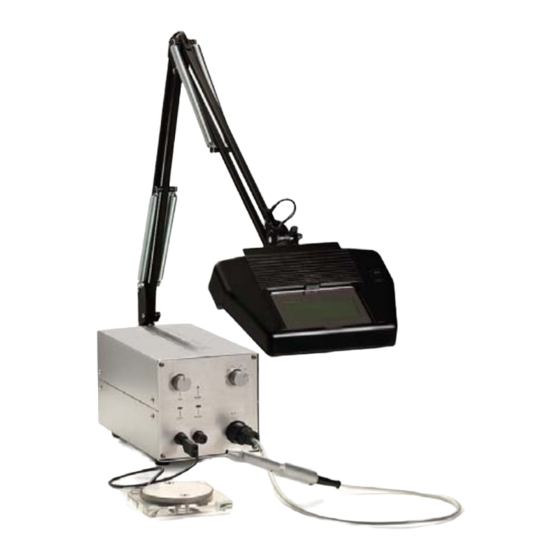
- Page 1 Operating Instructions Precision Welding Device PUK 111 PUK - Optic Device Lampert Tools USA, Inc 115 V...
- Page 3 Operating Instructions 115V Dear Customer This handbook is intended to help you with the Note on Symbol operation of your PUK 111. It is important to read equipment manufactured “Lampert the instructions carefully and to follow the TOOLS GmbH“ fulfil the standard requirements...
-
Page 4: Table Of Contents
TABLE OF CONTENTS SECTION 1 – GENERAL APPLICATION ........SECTION 2 –... -
Page 5: Section 1 - General Application
SECTION 1 – GENERAL APPLICATION • • fixing or fastening work pieces prior to not authorized for welding teeth fittings soldering or other additional processing (dental techniques) • Operation in outdoor areas is prohibited. Use • the placement of spot welding on precious in dry room areas only. -
Page 6: Personal Protection And Danger
PUK111 can be operated in series using a device should only be opened mains voltage of 115V~ authorized customer service, otherwise the manufacturer`s warrantee is invalid. Yellow/green electric conductor = grounded terminal (PE) if the device is setup for a special voltage, Other conductors L1 and N are connected to technical data contained on the output sticker phase and neutral of plug. -
Page 7: Section 4 - Safety Precautions - Read Before Using
SECTION 4 – SAFETY PRECAUTIONS - READ BEFORE USING 4-1. Arc Welding Hazards ► The symbols shown below are used throughout this _ Do not connect more than one electrode or work cable to manual to call attention to and identify possible any single weld output terminal. - Page 8 WELDING can cause fire or explosion. MAGNETIC FIELDS can affect Welding on closed containers, such as pacemakers. tanks, drums, or pipes, can cause them to blow up. Sparks can fly off from the _ Pacemaker welding arc. The flying sparks, hot wearers keep away.
-
Page 9: Additional Symbols For Installation, Operation, And Maintenance
4-2. Additional Symbols For Installation, Operation, And Maintenance FIRE EXPLOSION MOVING PARTS can cause hazard. injury. _ Do not install or place unit on, _ Keep away from moving parts such over, or near combustible surfaces. as fans. _ Do not install unit near flammables. _ Keep all doors, panels, covers, and _ Do not overload building wiring –... -
Page 10: Principal Safety Standards
4-3. Principal Safety Standards Safety in Welding, Cutting, and Allied Processes, ANSI Boulevard, Rexdale, Ontario, Canada M9W 1R3 (phone: Standard Z49.1, from American Welding Society, 550 800–463–6727 or in Toronto 416–747–4044, website: N.W. LeJeune Rd, Miami FL 33126 (phone: 305-443- www.csa–in-ternational.org). -
Page 11: Section 5 - Installation
SECTION 5 – INSTALLATION 5-1. TECHNICAL DATA: Device suitable for welding in dry rooms. Protective gas min. Argon 99.9 % Mains voltage ~ 115 V / 50-60 Hz +/- 15% “Argon grade 5” (ARGON 4.6) Mains fuse T4,0 A max. gas pressure 10 bar Power input 500VA Protection class I Operating voltage 20-38 V... -
Page 12: Setting Up
Ready for use signal (4) (green when device is ready for welding) RESET Sockets (5) for connection of contact elements such as welding table, welding clamp, holding pliers. PUK 111 WAIT READY Output regulator (6) . Power regulated in 8 steps Connecting socket for tool piece (7) -
Page 13: Starting The Welding Process
5-5. STARTING THE WELDING PROCESS: • The device must be set up on a flat and stable To connect the microscope, plug in the round surface, a work table is best suitable. plug and fasten it as like the optic unit above. •... -
Page 14: Section 6 - Operation
SECTION 6 – OPERATION 6-1. WELDING GUIDELINES • • Place the work piece on the welding table welding process takes place • automatically: Make sure there is good contact between protective gas floats around welding spot work piece and table •... -
Page 15: Grinding The Electrodes
6-3. GRINDING THE ELECTRODES The electrodes must be ground on a fine or medium diamond wheel. The angle should be about 25°. (Figure 4) Figure 4 25° SECTION 7 – MAINTENANCE AND TROUBLESHOOTING 7-1. ROUTINE MAINTENANCE • PUK111 requires a minimum amount of care and Occasionally check mains plug and cables maintenance when used under normal operating and welding cable for damage. -
Page 16: Troubleshooting
7-2. TROUBLESHOOTING CHECK LIST ERROR CAUSE SOLUTION 1. No welding power Mains switch turned on Operation Interrupted cable Check cable and Mains signal does not light up 2. No welding power Welding cable connection Check connections Mains switch turned on interrupted. -
Page 17: Section 8 - List Of Spare Parts
SECTION 8 – LIST OF SPARE PARTS LIST OF SPARE PARTS Hand piece 150 151 100 100 complete hand piece 100 150 extrusion die 100 151 pliers 100 152 tension nut Welding table 100 300 Welding table complete with 500mm cable Electrodes 100 400 10 electrodes in display box (thoriumoxide-free) -
Page 18: Section 9 - Contact
SECTION 9 – CONTACT Lampert Tools USA, Inc. 67 East Madison, #512 Chicago, IL 60603 Phone: 1-866-4-PUK111 (1-866-478-5111) Fax: 1-312-641-2678 info@lampertusa.com www.lampertusa.com... - Page 19 This handbook is intended to help you with the Note on Symbols operation of your PUK Optic Device. It is important The equipment manufactured by “Lampert Tools to read the instructions carefully and to follow the GmbH“ fulfil the standard requirements of CE...
- Page 20 TABLE OF CONTENTS SECTION 1 – GENERAL APPLICATION ........SECTION 2 –...
-
Page 21: Section 3 - General Safety Instructions - Read Before Using
SECTION 3 – GENERAL SAFETY INSTRUCTIONS - READ BEFORE USING 3-1. SAFETY INSTRUCTIONS • from the mains. In the case of more complex Opening the device is permitted only by activity where you must leave the work area – trained experts. Before opening the device, even for a short time –... -
Page 22: Principal Safety Standards
4-2. Principal Safety Standards Safety in Welding, Cutting, and Allied Processes, ANSI Standard Z49.1, from American Welding Society, 550 N.W. LeJeune Rd, Miami FL 33126 (phone: 305-443-9353, website: www.aws.org). Recommended Safe Practices for the Preparation for Welding and Cut-ting of Containers and Piping, American Welding Society Standard AWS F4.1, from American Welding Society, 550 N.W. -
Page 23: Section 5 - Operation And Instructions
OPERATION AND INSTRUCTIONS SECTION 5 – 5-1. SETTING UP • • Plug the optic device into the holder (3) Keep a minimum 15 cm distance between the • light and the workpiece and/or the welding Insert lights into the holder with a maximum of table. -
Page 24: Technical Data
(Fig . 2) LAMP HOLDER (3) CONNECTIVE PLUG (4) SOCKET (5) MAINS CABLE (6) 5-3. TECHNICAL DATA • Optical view protection and lighting unit for the • Lighting material = energy saving lamps with exclusive use with PUK precision devices max. -
Page 25: Section 7 - Contact
SECTION 7 – CONTACT Lampert Tools USA, Inc. 67 East Madison, #512 Chicago, IL 60603 Phone: 1-866-4-PUK111 (1-866-478-5111) Fax: 1-312-641-2678 info@lampertusa.com www.lampertusa.com...