
Related Manuals for Lampert PUK 6


Summary of Contents for Lampert PUK 6
- Page 1 OPERATING MANUAL Lampert Werktechnik GmbH Fine welding device Issue EN 2022/05...
- Page 2 Product : Fine welding device Type: PUK 6 Manufacturer: Lampert Werktechnik GmbH Ettlebener Strasse 27 97440 Werneck Telefon: +49 (0)9722 94 59 – 0 Telefax: +49 (0)9722 94 59 – 100 E-Mail: mail@lampert.info Website: www.lampert.info Revision index: – Date of revision:...
-
Page 3: Table Of Contents
Selection and qualification of personnel ............14 Safety devices...................... 15 Safety signs ......................16 Structure and function ..................18 Functional description ..................18 Scope of delivery ........................18 General overview ....................19 3/56 Issue EN 2022/05 PUK 6 Operating manual... - Page 4 Contents PUK 6 ........................20 Handpiece with connection cable ............... 24 Optional electrode grinding motor (item number 100 858) ........ 25 Optional foot switch (item number 100 850) ............26 Type plate ......................27 Transport and storage ..................28 Transport ......................28 Storage .........................
- Page 5 Standby mode ...................... 43 Using the PUK 6 ....................44 Adjusting the gas flow ..................44 Switching on the PUK 6 ..................44 Welding with the PUK 6 ..................45 Switching off the PUK 6 ..................47 Basic information and tips ................... 47 Help with faults ....................
-
Page 6: About This Operating Manual
Safety and danger notices on the device must be kept in legible condition and must not be removed, covered or damaged. 6/56 Issue EN 2022/05 PUK 6 Operating manual... -
Page 7: Presentation Of Information
The result symbol describes the result or intermediate result of an ac- tion. Application tip The "TIP" indicates additional information for easy and safe use of the de- vice. TIP: Note on the optimal use of the device. 7/56 Issue EN 2022/05 PUK 6 Operating manual... -
Page 8: Structure Of The Warnings
Type of hazard (description of the hazard) • Consequences of the hazard (description of the consequences of the hazard) • Hazard prevention (measures to prevent the hazard) DANGER! Type of hazard Consequences of hazard Hazard prevention 8/56 Issue EN 2022/05 PUK 6 Operating manual... - Page 9 Warning about the danger of hand injuries. Hot surfaces Warning of hot surfaces. Pressurised containers Warning of fire and explosion hazard. Optical radiation Warning of optical radiation. Hazard due to electromagnetic radiation Warning of electromagnetic fields. 9/56 Issue EN 2022/05 PUK 6 Operating manual...
-
Page 10: General Safety Regulations
- up to 50 % at 40 °C (104 °F) • - up to 90 % at 20 °C (68 °F) The ambient air should be free of dust, acids, corrosive gases or substances. 10/56 Issue EN 2022/05 PUK 6 Operating manual... -
Page 11: Foreseeable Misuse
• Eye protection • Dry clothing (non-synthetic and flame retardant) Furthermore, the workplace must be sufficiently ventilated. If this cannot be ensured by fresh air supply, an exhaust system must be installed. 11/56 Issue EN 2022/05 PUK 6 Operating manual... -
Page 12: Handling Protective Gas Cylinders
Before each start-up of the device, make sure that the gas connection on the back of the device as well as the connection on the flow regula- tor have been hand-tightened without tools. 12/56 Issue EN 2022/05 PUK 6 Operating manual... -
Page 13: During Operation
• The contact clamp for fixation welding must be removed from the blue socket on the right hand side of the PUK 6 ( - ) again after fixation weld- ing has been completed. In normal welding operation, always make sure that the contact clamp for fixation welding is not connected to the device. -
Page 14: During Disassembly
The safety-conscious working of the personnel must be checked at regular intervals. All persons who are instructed to work on the device undertake, before starting work, to • observe the fundamental regulations governing occupational safety and accident prevention 14/56 Issue EN 2022/05 PUK 6 Operating manual... -
Page 15: Safety Devices
2.7 Safety devices • The device has a thermal cut-off device that is activated if the heat build-up is too high, preventing the device from overheating. 15/56 Issue EN 2022/05 PUK 6 Operating manual... -
Page 16: Safety Signs
Electromagnetic fields may impair the function of pacemak- ers. Inhaling welding fumes can endanger your health. Arcs can damage the eyes and injure the skin. Welding sparks may cause an explosion or fire. 16/56 Issue EN 2022/05 PUK 6 Operating manual... - Page 17 The union nut of the protective gas hose may only be tight- ened by hand on the protective gas connection. The use of tools (e.g. wrenches) can damage the protective gas con- nection. Tab. 2.1 Safety sign 17/56 Issue EN 2022/05 PUK 6 Operating manual...
-
Page 18: Structure And Function
Structure and function 3.1 Functional description The PUK 6 is a micro-pulse TIG welder. The welding process is controlled by the central control and regulation unit of the PUK 6. For a precise welding process and a perfect result, the welding process is continuously monitored and the target parameters are adjusted as required using control algorithms. -
Page 19: General Overview
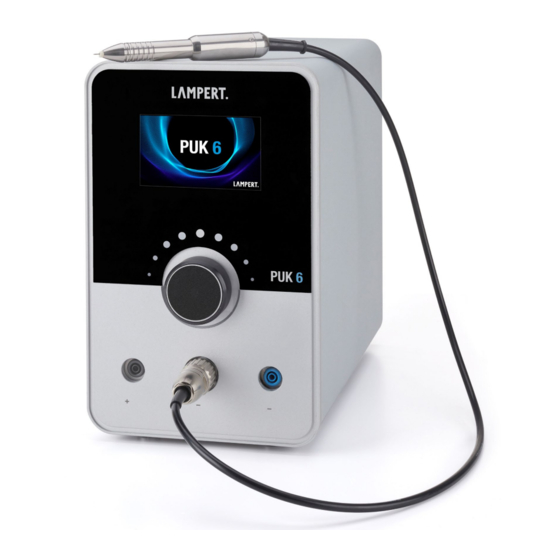
Structure and function 3 3.2 General overview Fig. 3.1 Overview of PUK 6 with handpiece PUK 6 Handpiece with connection cable 19/56 Issue EN 2022/05 PUK 6 Operating manual... -
Page 20: Puk 6
3 Structure and function 3.3 PUK 6 Fig. 3.2 PUK 6 Front Display Turn-push controller with tilt function Socket (-) for contacting tools (fixation welding) Handpiece connection socket (-) for the welding handpiece Socket (+) for contacting tools (spot welding) Display Displays the user interface of the operating software. - Page 21 For connecting contact elements for fixation welding. Socket (-) for contacting tools For connecting the handpiece. Handpiece socket (-) For connecting contact elements such as welding table, contact terminals or Socket (+) for contacting clamps. tools 21/56 Issue EN 2022/05 PUK 6 Operating manual...
- Page 22 3 Structure and function 2 3 4 Fig. 3.3 PUK 6 Rear Type plate Bus connection USB connection LAN connection Mains switch Fuse compartment IEC-60320 C14 socket Protective gas connection Mains voltage approved for this device Ventilation opening Connection socket for foot switch...
- Page 23 A foot switch with M12 connection can be connected to this socket. Connection socket for foot switch A Lampert electrode grinding motor from the accessories range can be con- Connection socket for nected to this socket. electrode grinding motor...
-
Page 24: Handpiece With Connection Cable
The hand- nozzle piece can be guided freely (appropriate eye protection required) or clamped in a corresponding device (e.g. handpiece holding arm of a Lampert welding microscope). The nozzle with ceramic insert ensures the targeted gas supply at the welding location. -
Page 25: Optional Electrode Grinding Motor (Item Number 100 858)
(15° angle, Ø 0.5, 0.6, 0.8, 1.0 mm) and an on/off button. Connection cable with The connection cable is screwed with the M12 plug to the corresponding socket on the rear of the welding device housing. plug 25/56 Issue EN 2022/05 PUK 6 Operating manual... -
Page 26: Optional Foot Switch (Item Number 100 850)
(workpiece contact) is deactivated. When the fixation welding mode is selected, the foot switch is permanently activated. Connection cable with The foot switch connection cable with M12 plug is screwed to the back of M12 plug the welding device. 26/56 Issue EN 2022/05 PUK 6 Operating manual... -
Page 27: Type Plate
Maximum rated welding current at 20 °C ambient temperature No-load peak value Symbol for the welding process: Tungsten inert gas welding here Symbol for the welding current: DC here Welding current source symbol: Single-phase transformer here Manufacturer's type designation 27/56 Issue EN 2022/05 PUK 6 Operating manual... -
Page 28: Transport And Storage
For longer storage, disconnect the mains plug and cut off the gas supply. The storage location of the device must be dry and dust-free and must not be subject to extreme temperatures (colder than -20 °C or hotter than +55 °C). 28/56 Issue EN 2022/05 PUK 6 Operating manual... -
Page 29: Commissioning
Fasten the appropriate flow regulator to the shielding gas cylinder with the corresponding tool. ATTENTION: In doing so, observe the separate operating instructions provided by the manufacturer. • Use only inert gases as shielding gas, e.g. argon 4.6 29/56 Issue EN 2022/05 PUK 6 Operating manual... -
Page 30: Connect Eye Protection
5 Commissioning 5.3 Connect eye protection Warning! Only suitable original eye protection systems from Lampert may be connected to the welding system! Other eye protection systems can lead to permanent health damage or damage to the welding device. The operat- ing instructions of the respective personal protective equipment (micro- scope) must be observed. -
Page 31: Adjusting The Electrode Length
Now hand-tighten the nut and fit the argon nozzle. (See Fig. 5.2) If you do not have a Lampert welding microscope, clamp the tung- sten electrode in the handpiece so that it protrudes approx. 4 - 6 mm beyond the nozzle. -
Page 32: Connecting The Handpiece
The optional accessories (e.g. grinding motor or foot switch) are connected via the M12 plug attached to the connection cable. The respective sockets on the back of the device are colour-coded for this. Always tighten the plugs only hand-tight. 32/56 Issue EN 2022/05 PUK 6 Operating manual... -
Page 33: Graphical User Interface
Performing test functions • Showing error messages 6.1 Main menu Fig. 6.1 Main menu Material selection Menu bar Foot switch activated (optional) Geometry selection Pulse duration in milliseconds Speed levels Welding power (in percent) 33/56 Issue EN 2022/05 PUK 6 Operating manual... -
Page 34: Material Selection
Here you select the material to be processed. The following materials are available for selection: Abbreviation Material designation Universal Gold Silver Platinum Palladium CuSn Bronze Stainless steel Titanium CuZn Brass Copper Tab. 6.1 Material selection 34/56 Issue EN 2022/05 PUK 6 Operating manual... -
Page 35: Welding Power And Pulse Duration
Welding power Pulse duration Blue range To make welding with the PUK 6 easier, a value range for the welding power and pulse duration is marked blue in the display as a recommenda- tion for each material-geometry combination. Foot switch (optional, The foot switch is activated by pressing the connected foot switch for a longer time (approx. - Page 36 20 % and slowly work up to higher powers. To make welding with the PUK 6 easier, a value range for the welding power is marked blue in the display as a recommen- dation for each material-geometry combination.
-
Page 37: Menu Bar
The menu bar can be used to switch to the various menu and setting levels. Fig. 6.4 Menu bar The menu bar consists of the following menu levels: Main menu Micro mode Fixation mode Settings menu Standby mode 37/56 Issue EN 2022/05 PUK 6 Operating manual... -
Page 38: Geometry Selection
Melting of welding wire. Use identical alloy wire with a diameter of ca. 0.4 Application of welding wire on claws and stone settings. Particularly low- energy melting of thin welding wire with a diameter of ca. 0.2 mm. 38/56 Issue EN 2022/05 PUK 6 Operating manual... -
Page 39: Speed Levels
Micro mode is suitable for particularly sensitive materials and thin material thicknesses. In micro mode, the pulse duration is always preselected as the focus because it is critical for the introduction of heat into the workpiece. In 39/56 Issue EN 2022/05 PUK 6 Operating manual... -
Page 40: Fixation Mode
During fixation welding, the foot switch is always active, and cannot be de- activated! The shielding gas flow is deactivated during fixation welding. TIP: Fixation welding is particularly well suited for metals with low conductivity, for example titanium or steel. 40/56 Issue EN 2022/05 PUK 6 Operating manual... -
Page 41: Settings Menu
Here the eye protection filter is activated and thus darkened. With this func- tion, the Lampert eye protection system can be checked for correct function. Here the gas valve in the device is opened. This function is used to be able to set the gas flow correctly on the flow controller (recommended gas flow 2 –... -
Page 42: Update Menu
The device software is now updated. If the update was not successful, the above steps must be repeated. If the update did not work even after repeated attempts, please contact customer service. 42/56 Issue EN 2022/05 PUK 6 Operating manual... -
Page 43: Standby Mode
If you do not use the device for more than one hour between two applica- tions, we always recommend that you switch the device off completely us- ing the mains switch for optimum energy consumption. 43/56 Issue EN 2022/05 PUK 6 Operating manual... -
Page 44: Using The Puk 6
The gas flow is now set correctly. 7.2 Switching on the PUK 6 CAUTION! Danger due to operating errors As soon as the device is switched on at the mains master switch, voltage is applied to the contact tools. -
Page 45: Welding With The Puk 6
Set the power switch to "I". Read the safety instruction on the display and confirm it by pressing the rotary-push control. The device is now ready for operation 7.3 Welding with the PUK 6 CAUTION Hot surfaces Danger of burns to the skin It is absolutely essential to wear gloves when welding ... - Page 46 7 Using the PUK 6 Proceed as follows: Check the function of the eye protection filter. To do this, connect the eye protection system to the welding device. Press the button for the eye protection test in the settings menu of the welding device. This darkens the field of vision.
-
Page 47: Switching Off The Puk 6
Using the PUK 6 7 7.4 Switching off the PUK 6 Proceed as follows: Set the contact clamp down such that no accidental contact can take place. Switch off the device at the main switch on the back of the device. -
Page 48: Help With Faults
Device begins to weld imme- Malfunction Immediately put the device out of oper- diately when touching the ation and contact customer service workpiece (no gas pre-flow) Tab. 8.1 Causes of errors and fault rectification 48/56 Issue EN 2022/05 PUK 6 Operating manual... -
Page 49: Care And Inspection Work
Grind the electrode at a 15° angle. With the grinding motor from the PUK 6 original accessories, this angle is predetermined by the guide holes. Now the electrode can be reinserted into the handpiece. -
Page 50: Disposal And Recycling
EU countries: In accordance with European directive 2012/19/EU regarding the disposal of used electrical and electronic equipment, discarded electri- cal devices must be separated and collected and sent for recovery in an en- vironmentally friendly manner. 50/56 Issue EN 2022/05 PUK 6 Operating manual... -
Page 51: Dimensions And Technical Data
Dimensions and technical data 11 11 Dimensions and technical data 11.1 Device dimensions Name Value Unit Earth Earth Length Width Height Tab. 11.1 Machine dimensions 51/56 Issue EN 2022/05 PUK 6 Operating manual... -
Page 52: Technical Data For The Device
Up to 50 % at 40 °C Up to 90 % at 20 °C Max. location altitude (above sea level) 1000 Protection type per EN 60529:2014 IP21S Shielding gas Argon Tab. 11.2 Technical data for the machine 52/56 Issue EN 2022/05 PUK 6 Operating manual... -
Page 53: Appendix
Germany +49 9722 9459 0 mail@lampert.info 12.2 Spare and wear parts Only original spare and wear parts may be used for your PUK 6. These are listed in the Lampert spare parts catalogue and on the manufacturer's web- site. 53/56... -
Page 54: Ce Conformity
12 Appendix 12.3 CE conformity 54/56 Issue EN 2022/05 PUK 6 Operating manual... - Page 55 Appendix 12 55/56 Issue EN 2022/05 PUK 6 Operating manual...
- Page 56 All contents of these operating instructions, in particular text, photographs and graphics, are pro- tected by copyright. The copyright is held by Lampert Werktechnik GmbH, unless expressly stated otherwise. Lampert Werktechnik GmbH reserves the right to change this documentation and the descriptions, dimensions and technical data contained therein without prior notice.