
Related Manuals for Leviton Topaz 12


Summary of Contents for Leviton Topaz 12
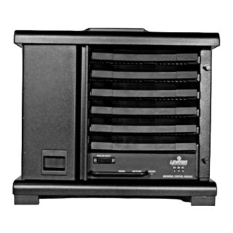
- Page 1 TOPAZ 12 PORTABLE PACK ASSOCIATED CONTROL MODULES USER GUIDE (Part # LIT-29433-1A) © Copyright March 2002 Leviton Manufacturing Co. Inc.
-
Page 2: Table Of Contents
TABLE OF CONTENTS CHAPTER I: USING THIS MANUAL……………………………………………... CHAPTER II: PORTABLE PACK INSTALLATION………………………………. CHAPTER III: REMOTE CONTROL MODULE…………………………………… CHAPTER IV: UNIVERSAL CONTROL MODULE……………………………….. 10 CHAPTER V: FINAL ASSEMBLY…………………………………………………. 17 CHAPTER VI: MAINTENANCE AND ADJUSTMENT……………………………. 18 CHAPTER VII: TROUBLE SHOOTING…………………………………………….. 19 APPENDIX A: SPECIFICATIONS………………………………………………….. -
Page 3: Chapter I: Using This Manual
The TOPAZ 12 Pack is an extremely versatile piece of equipment which can be tailored to meet the needs of any small to medium-sized dimming application. This manual is designed to assist you in identifying each of the parts of your system and to correctly connect each of those parts. -
Page 4: Chapter Ii: Portable Pack Installation
A. PACK LOCATION The TOPAZ 12 Pack should be located in a dust-free space with an ambient temperature between 32 - 104°F (0-40°C) and a relative humidity of 10 - 90% without condensation. It should be located on a stable surface suitable for supporting the weight indicated in Appendix A, Specifications. - Page 5 The TOPAZ 12 Pack comes wired from the factory to accept a 3 phase, 4 wire, wye service with equipment ground. If this is the type of service which will be used for your particular installation, connect the line wiring to the A, B, C, Neutral and Ground Lugs, See Figure 2;...
- Page 6 If the service you have available is a single phase, 3 wire (split phase) service, convert the pack using the following directions: Phase Conversion Loosen the four bolts on the dimmer power feed busses using a 7/16" socket wrench. See figure 3. Rotate the Phase B1 jumper bar up so that it connects to the Phase A bus.
- Page 7 The TOPAZ 12 PACK dimmer module is available in 1.8kW or 2.4kW sizes for 120V operation, and 2.5kW for 240V operation. The 1.8/2.4/2.5kW modules are dual dimmers. The model number may be found on the bottom of each dimmer module.
-
Page 8: Chapter Iii: Remote Control Module
CHAPTER III: REMOTE CONTROL MODULE MODEL NO. LEC2102 - 120V The purpose of the Remote Control Module is to control the TOPAZ 12 Pack when only a digital multiplexed control signal is used. The remote control module automatically detects whether the control signal is DMX512 or CMX (Colortran's version of DMX) protocol upon power-up, reset or first appearance of a valid control signal. - Page 9 Status Control Console Jumper 4. STATUS CONTROL CONSOLE JUMPER (JP 5, internal, Figure 5) IMPORTANT: This jumper should ONLY be moved when using a Status control console, moving the jumper and using any other control console may damage the control console. By placing the jumper in the "Status"...
- Page 10 The control module is preset at the factory for 120 or 240 volts and should not require further phase trim adjusting; but if you are using the TOPAZ 12 Pack in an environment that has unusually high or low voltage, including 100V or 220V, the phase trim will need to be adjusted.
- Page 11 Push the module in firmly making sure that the edge connectors are making full contact. Control wiring to this module is via the 5-pin XLR connectors on the back of the pack. See Figure 6. If LEVITON control cables are not available, cables must be made using Neutrik NC5MX-B (male) and NC5FX-B (female), or equivalent connectors, and Belden 9829 or equivalent cable.
-
Page 12: Chapter Iv: Universal Control Module
CHAPTER IV: UNIVERSAL CONTROL MODULE, MODEL NO. 600-902 - 120V The purpose of the Universal Control Module is to control the TOPAZ 12 Pack when a digital or analog multiplexed control signal and/or standard analog control signals are used. When in the digital multiplex mode, the Universal control module automatically detects whether the control signal is DMX512 or CMX (Colortran’s version of DMX) protocol upon... - Page 13 2. RESET SWITCH (Front Panel, Figure 7) If a control module becomes inoperative or "freezes", the Reset Switch should be pressed. This will cause a "warm boot" of the system and it should resume normal operations. 3. TEST SWITCH (Front Panel, Figure 7) This switch is used to test the individual outputs of each dimmer without the use of a signal from a lighting console.
- Page 14 DIP Switches Figure 8 - Universal Control Module Internal Switches Non-Dim Switches Figure 9 - Universal Control Module Non-Dim Switches Page 12...
- Page 15 6. DIP SWITCHES (Red Switches Numbered 1 thru 3, Internal, Figure 8) These switches offer a large range of configurations in which the module can operate. The operation of each switch is explained below. Note that switches 1 thru 3 offset only the multiplexed control and not the analog control. SWITCH NO.
- Page 16 8. FRONT PANEL LED'S (Front Panel, Figure 7, Page 10) SIGNAL INDICATOR (Green) This LED senses the presence of a digital signal from the lighting console. If a digital signal is correctly applied, the LED will glow solid green. If signal is not present or incorrectly applied, the LED will either not turn on or will flicker.
- Page 17 The control module is preset at the factory for 120 or 240 volts and should not require further phase trim adjusting; but if you are using the TOPAZ 12 Pack in an environment that has unusually high or low voltage, including I00V or 220V, the phase trim will need to be adjusted.
- Page 18 After you have made all necessary settings on the Universal Control Module, you can install it into the TOPAZ 12 pack. Push the module in firmly making sure that the edge connectors are making full contact. Multiplex control wiring to this module is via the 5-pin XLR connectors on the back of the Pack. See Figure 10. If LEVITON control cables are not available, cables can be made using Neutrik NC5MX-B (male) and NC5FX-B (female), or equivalent connectors and Belden 9829, or equivalent cable.
-
Page 19: Chapter V: Final Assembly
(Note to Canadian users: CSA requires screwdriver-installed screws in lieu of thumb screws. Two 8-32 x 1/2 screws are provided for this purpose.) 9. Test the dimmers using control console. THIS COMPLETES THE INSTALLATION OF THE TOPAZ 12 PACK DIMMING SYSTEM. IF THERE ARE ANY TECHNICAL QUESTIONS OR DIFFICULTIES, SEE CHAPTER VIII: TROUBLESHOOTING. CHAPTER V: FINAL ASSEMBLY... -
Page 20: Chapter Vi: Maintenance And Adjustment
IMPORTANT: Disconnect Pack from power source before performing any maintenance. 1. MAINTENANCE The only maintenance which should be required on the TOPAZ 12 Pack is the occasional cleaning of the dimmer modules and the tightening of the feeder bus bar lugs. -
Page 21: Chapter Vii: Troubleshooting
Before requesting service for this unit, check the charts below for a possible cause of the problem you are experiencing. Some simple checks or a minor adjustment on your part may eliminate the problem and restore proper operation. If you are in doubt about some of the checkpoints, or if the remedies indicated in the chart do not solve the problem, consult your local dealer or call the NSI Technical Support line for assistance. -
Page 22: Appendix A: Specifications
APPENDIX A: SPECIFICATIONS PACK CAPACITY: DIMENSIONS: WEIGHT: EMPTY: LOADED: NOMINAL INPUT: 120V CIRCUITS 240V CIRCUITS (FOREIGN ELECTRICAL SERVICE ONLY) POWER FEEDER ENTRY: MAXIMUM FAN NOISE RATING: MAXIMUM AMBIENT OPERATING TEMPERATURE: MAXIMUM OPERATING HUMIDITY PHASE-TO-NEUTRAL OPERATING VOLTAGE: OPERATING FREQUENCY: ENCLOSURE TYPE: 12 CIRCUITS, 20AMP MAX PER CIRCUIT 13.00"H x 14.65”W x 9.63"D (33.0cm) x (37.2cm) x (24.4cm) -
Page 23: Appendix B: Dimmer Pack Feeder Cables
APPENDIX B: DIMMER PACK FEEDER CABLES The 2002 National Electrical Code allows for smaller, lighter, less expensive cables, providing the terminations on each end are capable of dealing with the elevated temperatures. All Pack terminations are rated to operate at the elevated temperatures at which 90˚C rated cables operate. Proper selection is dependent on the rating of the terminations on the opposite end of the cable. -
Page 24: Appendix C: Load Connectors
INTERLOCK STACKING CAPABILITIES The TOPAZ 12 Pack is designed so that several units can be stacked on top of each other. The channel on the bottom of the packs is designed to fit over the handle on the top and the rubber feet minimize slipping. Numerous packs can be stacked on top of each other as stability permits.