
Related Manuals for Leviton i Series e


Summary of Contents for Leviton i Series e
-
Page 1: Users Guide
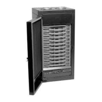
& i series Quad Dimmer Racks Users Guide Software Version #1.50 P/N: LIT-31903-00 April 2003... - Page 2 Tualatin, Oregon 97062 -or- Leviton Lighting Controls Division Technical Services 20497 SW Teton Tualatin, Oregon 97062 (800)959-6004 - voice (503)404-5601 - fax Leviton Manufacturing Company Incorporated. i Series e Users Guide LIT-31903-00 © Copyright 1998,2003 All Rights Reserved. Page 2 of 35...
-
Page 3: Table Of Contents
I SERIES E HHT – LOCAL MODE – DIMMER VIEW ...22 Dimmer View Menu ...22 Selecting Dimmers in the Dimmer Display...25 I SERIES E HHT – LOCAL MODE – FORCE DIMMER –OR- DIMMER CHECK...25 I SERIES E HHT – LOCAL MODE – DIMMER PROFILE EDITING...26 Edit Screen...26 I SERIES E HHT –... -
Page 4: New Features
Lutron Hi-Lume/Eco-10 d. Low Voltage, Magnetic Transformer Configuration Security Features & Password system This revise users manual includes configuration and usage information for all of the previous, modified and new features. i Series e Users Guide LIT-31903-00 Page 4 of 35... -
Page 5: I Series E Overview
All other individual parameters for the rack are stored in the socketed serial EEPROM chips on the i series e backplane. On power up, the control module automatically loads all the unique information from the serial EEPROMS on the... -
Page 6: Patch Assignments (Dmx-512 & Luma-Net Channel Numbers)
In each column is given an address range. This the range of address patched from the control source (DMX-512 or Luma-Net) to the dimmer number. Dimmer numbers are either sequential or phase balanced. i Series e Users Guide LIT-31903-00 i24e w/JP1 In... -
Page 7: Dimmer Numbering - Sequential Vs. Phase Balanced
The violet i Light indicates the current operating status of the rack. The indications are as follows i LIGHT ON : i LIGHT OFF : i LIGHT FLASHING : i Series e Users Guide LIT-31903-00 Sequential Patch Phase-Balanced Patch 13,14... -
Page 8: Dimmer Module Indicators - I Series E
Dimmer Module Indicators – i Series e On the front of each dimmer module are several indicators which indicate the current operating condition of the dimmer module. STATUS LED OFF : STATUS LED GREEN : STATUS LED YELLOW : This dimmer module is in Overtemp Warning. -
Page 9: Control Module -- Power Led's
PANIC LED LED OFF : LED ON: FLASHING ALTERNATE WITH i Series e Users Guide LIT-31903-00 The indicated phase is within the specified operating voltage of between 90-135V or 200-260V. The power source on the indicated Phase is either too low, or non-existent. - Page 10 LED OFF : RESET LED LED ON : LED OFF : i Series e Users Guide LIT-31903-00 Emergency mode causes only the panic scene to be activated. All other input control sources are disabled. For Version 1.2 software, the diagnostic led only comes on: *During the boot sequence *When a button has been pressed on the Hand Held Remote.
-
Page 11: Control Module - Abnormal Led Diagnostics
DMX OK,ANALOG, PANIC, AND BACKUP for about 30 seconds then operates normally. i Series e Users Guide LIT-31903-00 No power to rack, or no power to control module. Pull the control module. This will turn on the fan to full if there is power to the rack. -
Page 12: Dmx-512 Input Snapshot Procedure
DMX-512 Input Snapshot Procedure The i series e Control Module has the ability to store scenes in the rack itself. The scenes are saved from a snapshot picture taken of the levels coming in on the DMX-512 control line. When the record sequence is triggered, the Scene is copied from the DMX-512 input and stored in the EEPROM on the backplane of the control module. -
Page 13: The 12 Analog Scenes
[ T/C of Remembrance station ] connects to [ T/C of TB2 on i series e Backplane ] [ A1 through A12 of Remembrance station ] connects to [ A1 through A12 of TB4 ] on i series e Backplane DMX Snapshot Record Mode: Activate the scene to be recorded on the DMX-512 input port. -
Page 14: The Backup Scenes
The control modules will auto-increment to the next scene on completion of the cross fade. Press [GO] to execute the next crossfade, or [ENTER] to change the next scenes fade time, or completely change the next backup look # . i Series e Users Guide LIT-31903-00 Page 14 of 35... -
Page 15: I Series E Hand Held Terminal
Hand Held Terminal There are two operating modes for the i series e Hand Held Terminal (HHT): Local Mode (HHT plugged into the front connector of the control module) Remote Mode ( HHT connected through the Backplane Terminal Block TB2 ) -
Page 16: I Series E Hand Held Terminal - Local Mode
Hand Held Terminal – Local Mode Getting Started. To get started using your Hand Held Terminal (HHT), go to a powered up i series e dimmer rack and plug your Hand Held Terminal into the front of a control module. Please note that only one HHT may be plugged into the HHT wiring system at a time. -
Page 17: Main Local Menu
1.2 or later software, so please call (503) 404-5500 and ask to speak to a tech services representative. They will walk you through the i series e HHT configuration procedure. You should now be at the main local menu which is:... -
Page 18: I Series E Hht - Local Mode -- Display Rack View
HHT – Local Mode -- Display Rack View Press (RACK) or [S1] from the main menu. The LCD screen will then display the following: Display Rack – Main Screen S P L A Y U P P E R... - Page 19 Shows whether or not the Luma-Net restore option is activated (ON) or disabled (OFF). DMX512 START LUMA-NET START Shows the current start address for the DMX512 and Luma-Net input sources i Series e Users Guide LIT-31903-00 Page 19 of 35...
-
Page 20: I Series E Hht - Local Mode - Edit Config Rack
HHT – Local Mode – Edit Config Rack To change rack configuration options for this control module, you first enter configuration mode and then page through the screens and make your changes. The configuration screens are laid out the same as the display rack screens as discussed in chapter 3.2. -
Page 21: Config Rack - Change Rack Password
HHT screen goes blank. The default is now loaded. Proceed as if you had just plugged in the HHT by pressing any key. i series e HHT – Local Mode –Help Several help screens are available to walk users through setting the rack configuration parameters and give you additional basic information. -
Page 22: I Series E Hht - Local Mode - Dimmer View
HHT – Local Mode – Dimmer View Go to the main local menu. Assuming this control module has been set for rack 01 upper control module , 120VAC system, on a 60hz line, you will see the following:... - Page 23 This is the minimum level the dimmer will ever go to, regardless whether any of the control inputs tell it to go lower. This feature is useful for extending lamp life by eliminating the shock of cold tungsten inrushes, and i Series e Users Guide LIT-31903-00...
- Page 24 This is the DMX control channel that the current dimmer slot is patched to. This value is determined from the thumb -wheel address setting, the phase balanced or sequential jumper setting JP6 on the i series e BACKPLANE (installed = phase balanced / removed = sequential), or in the case of thumb -wheel address position 0, the DMX channel is determined from the custom patch stored on the eeprom of the back-plane.
-
Page 25: Selecting Dimmers In The Dimmer Display
HHT – Local Mode – Force Dimmer –or- Dimmer Check A dimmer check can be used any time you want to “force” the level of a dimmer to a particular point disregarding the instructions of any incoming control signal. -
Page 26: I Series E Hht - Local Mode - Dimmer Profile Editing
HHT – Local Mode – Dimmer Profile Editing To edit any of the setting on a per-dimmer slot basis, from the dimmer view screen, you follow the following procedure: From the dimmer view screen, press the (EDIT) softkey. -
Page 27: I Series E Hht - Local Mode - Custom Patches
LVMAG – standard square-law incandescent dimmer curve with adjustable cutoff in lieu of min and max level. NOTE: i Series e and QUAD will not control Mark VII fluorescent ballasts because there are no analog output circuits available. Then pressing that soft key will enter that “curve” into the edit screen and reorganize that screen appropriately. - Page 28 This is a quick way to create a custom “offset” patch. i series e HHT – Local Mode – Status_____________________ From the main local menu, there is a soft key option, [STAT], that mimics the state of the control input LED functions and displays the current control module status condition.
-
Page 29: I Series E Hht - Remote Mode - Hht Connection
HHT – Remote Mode – HHT Connection In order to activate the backup looks on the i series e rack (s), the hand held terminal must be plugged into a remote hand port that is wired to terminal block TB2 on the each of the racks. The pin out is as follows:... -
Page 30: I Series E Hht - Remote Mode - Go To Look
[REC LOOK] or [GO TO LOOK] menus. i series e HHT – Remote Mode – Go To Look To play backup looks, either plug in the HHT into the remote mode port, and press [GO TO LOOK] , or from... - Page 31 [ENTER] key, or a different look number and fade time may be entered. As with all the i series e HHT menu’s, the [ENTER] key increments cursor through the various selection fields, while the [BACK] softkey backs up a position or a field entry.
- Page 32 When you are finished playing backup looks, with the cursor on the most significant GO TO LOOK # digit, press the [BACK] key. This will return the system to the main menu where either [REC LOOK] or [GO TO LOOK] may be selected. i Series e Users Guide Page 32 of 35 LIT-31903-00...
-
Page 33: I Series E Maintenance
Every six months, check wire terminations for tightness: bus to bus, bus to lug, and lug to terminal or wire. Refer to the Installation Manual for the terminal-to-wire torque ratings and for other torque ratings. i Series e Users Guide LIT-31903-00... -
Page 34: I Series E Specifications
24.0 /M’ 78.7 /km PCC FT 1 Note: Belden 9830 may be substituted for Belden 9829 i Series e Users Guide LIT-31903-00 96/48 Circuits, 20 (120V) or 25A (240V) Amp max. per circuit 48/24 Circuits, 50 Amp max. per circuit 84.5”... -
Page 35: I Series E Limited Warranty
Leviton Manufacturing will repair or replace at its option, defective materials provided you have identified yourself as the original owner of the product to Leviton Manufacturing or any authorized Colortran dealer. Transportation charges to an authorized dealer or to the Leviton Manufacturing factory for repair shall be the responsibility of the owner.