Table of Contents
Advertisement
Quick Links
User Guide
-2000
a
D
IGITAL
12 & 24 C
Software revision 2.40 and above
D
TM
IMMER
C
ONTROLS
IRCUIT
C
ABINET WITH
V
ERSIONS
R
FULL
BRIGHT
PHASE LOSS
FULL BRIGHT
FAN
SELECT
SAVE
COMMUNICATION PORTS
AUXILIARY
DMX
CANCEL
LUMANET
CLEAR
20
PHASE
A
CONTROL
20
PHASE
B
20
PHASE
C
NORMAL
BYPASS
20
MODULE
1
20
20
MODULE
2
20
20
20
MODULE
3
NORMAL
BYPASS
20
MODULE
4
20
20
20
MODULE
5
20
MODULE
6
20
NORMAL
BYPASS
20
MODULE
7
20
20
MODULE
8
20
20
MODULE
9
20
NORMAL
BYPASS
20
MODULE
10
20
20
MODULE
11
20
20
20
MODULE
12
a-2000
TM
R
TUALATIN, OR
MADE IN U.S.A.
INDUSTRIAL CONTROL EQUIPMENT
LISTED
C
32300A
R
88H9
R
Advertisement
Table of Contents

Related Manuals for Leviton a-2000


Summary of Contents for Leviton a-2000
-
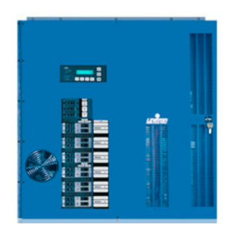
Page 1: User Guide
IGITAL 12 & 24 C IRCUIT Software revision 2.40 and above IMMER ONTROLS ERSIONS PHASE LOSS FULL BRIGHT COMMUNICATION PORTS AUXILIARY LUMANET a-2000 TUALATIN, OR MADE IN U.S.A. INDUSTRIAL CONTROL EQUIPMENT LISTED 32300A 88H9 ABINET WITH FULL BRIGHT SELECT SAVE... - Page 2 Notes:...
-
Page 3: Table Of Contents
DMX-512 ...32 DMX Wire Recommendation: ...32 Analog Input, 0-10 VDC (Optional) ...33 Photocell Input ...33 Multiple Signal Types ...35 External Full On/Emergency (Full Bright) ...36 a-2000 Dimmer Cabinets with Digital Controls Revision G November 2006 a-2000 User Guide Page 1... - Page 4 Verifying Assignment of Mark VII Analog Output Signal ...62 Step 13G: Daylight Harvesting/Photocells ...62 Background-Daylighting: ...62 Background-Photocells: ...63 Configuring your a-2000 cabinet to use a photocell: ...63 For example, to use this feature given the following installation: ...65 To Enable the dimmer for photocell control ...65 Page 2...
- Page 5 Warranty Information ........74 Limited Warranty ...74 Power Considerations for Control Systems ...77 Terminology ...77 Power Requirements & Maximum Run Length ...77 Power Wire - Run Length ...82 a-2000 Dimmer Cabinets with Digital Controls Revision G November 2006 a-2000 User Guide Page 3...
- Page 6 Page 4...
-
Page 7: Overview
Report all damage to the freight carrier who delivered the system. Claims for damages are filed with the freight carrier as all freight is shipped FOB Tualatin, Oregon. The a-2000 can be serviced in the field with replacement factory components in case of damaged parts. -
Page 8: Control Overview
Surface-mount and flush-mount units both include necessary mounting hardware. Control Overview The Leviton a-2000D Dimmer Cabinet uses an intelligent central control card (Digital Main Control Module), enabling the dimmers in this system to dim and control virtually any incandescent or fluorescent lighting load. The software can... -
Page 9: Feed And Load Wiring
Bypass, all the dimmer electronics are removed from the circuit and line is connected directly to load. Leviton normally ships the cabinet with all these switches in the Bypass position and all circuit breakers in the Off position. -
Page 10: Bypass Switch-Universal Units Only
Bypass Switch-Universal Units Only The bypass switch has two modes: Normal and Bypass. When the switch is set to Bypass (red LED illuminated) the SCR’s and relays are forced to turn on independent of the control module. Modules The dimmer modules simply slide and plug in. No tools are required, except for a shipping screw when dimmers are pre-installed at the factory. -
Page 11: Warnings
CIRCUIT BREAKER OR FUSE AND TEST THAT THE POWER IS OFF BEFORE WIRING, OPENING THE PANEL, OR REPLACING A DIMMER MODULE! a-2000 Dimmer Cabinets with Digital Controls Revision G November 2006 5a) Hook up flourescent control wiring, if required C copper wire at 75 a-2000 User Guide ampacity. Page 9... -
Page 12: Installation
Installation Installation Checklist - Non Universal 120V Units Install the cabinets by following these simple steps: Step 1 Step 2 Step 3 Step 4 Step 5 Step 6 Step 7 Step 8 Step 9 Step 10 Step 11 Step 12 Step 13 Installation Checklist - Non Universal 277V and Universal Units... -
Page 13: Step 1: Mounting
Class 2/PELV Wiring to Controls Wiring Raceway Feed Wiring Load Wiring Max Height to top of Circuit Breaker is 6' 7" Side View a-2000 User Guide 4" Min clearance to floor " self tapping screws " hardware to be Page 11... -
Page 14: Flush Mount
Figure 2 - Surface Mount Hardware Leviton recommends that cabinet mounting hardware reaches through the drywall and attaches to the wall studs. However, properly sized struts and suitable hardware can also be used. They must distribute the load to the anchors without exceeding the recommended anchor limit. - Page 15 User Guide Once the cabinet is mounted, proceed to Step 2: Feed and Load Wiring. Figure 3 - Flush Mounting Hardware a-2000 Page 13 Dimmer Cabinets with Digital Controls Revision G November 2006...
-
Page 16: Main Feed And Load Wiring
Main Feed and Load Wiring Step 2: Power Wiring - Feed\Line Wiring The entire right side of the dimmer cabinet is reserved for power wiring. Refer to Figure 4 and the cabinet labels for all appropriate wiring notes. The cabinet includes: •... - Page 17 Low Voltage Wiring Area High Voltage Connections Figure 4 - Typical Low Voltage and High Voltage Wire Connections a-2000 Dimmer Cabinets with Digital Controls Revision G November 2006 a-2000 User Guide Optional Main Breaker Page 15...
- Page 18 Note: Non Universal Cabinet pictured above Figure 5 - Appropriate Wireways for High and Low Voltage Wires Depending on the cabinet that was ordered, it will have either main lugs or a main breaker. See Table 4-5 for feeder information. Information shown is for feeder lugs only.
- Page 19 24, 36 #4-250kcmil 24, 36 #4-250kcmil #4-250kcmil Phase Max Feed Size Wire Size 125A #14-#2 AWG #14-#2 AWG 250A #6-250kcmil 250A #6-250kcmil 250A #4 - 250kcmil 175A #4 - 250kcmil 500A (2) #6-250kcmil 350A (2) #6-250kcmil a-2000 User Guide Page 17...
-
Page 20: Step 3: Load Circuit Wiring - 120 Volt Units
Table 6- Wire Combinations for Load and Neutral Block Preferred wire entry is from the right hand side of the cabinet. For all loads except Lutron’s Hi-Lume ®, Eco-10, Fluorescent dimming ballasts and the Leviton High Rise Dimmer Module: SWITCHED Figure 6 - Incandescent, Non-Dim and Constant Loads... - Page 21 Figure 7 - Load Terminal Wiring for Leviton High Rise Time Dimmer SWITCHED DIMMED Black - Dimmed Hot Figure 8 - Load Terminal Wiring for Advance Mark X Wire a-2000 Dimmer Cabinets with Digital Controls Revision G November 2006 Dimmed Hot/Live...
- Page 22 GRAY VIOLET Grey SWITCHED DIMMED Violet Black - Switched Hot Figure 9 - Load Terminal Wiring for 0-10 VDC Control Dimming Ballasts Orange - Dimmed Hot SWITCHED DIMMED Figure 10 - Load Terminal Wiring for Lutron Hi-Lume or Eco 10 Page 20 BALLAST 0-10 VDC...
-
Page 23: Step 4 - Relay Cabinet (Optional)
12 or 24 channel cabinet only at the factory. Figure 11 - Relay Cabinets Attached to a 24 Circuit a-2000 Cabinet (on left) and a 12 Circuit cabinet (on the right) - Page 24 +12VDC SENSE 1 +12DC 1 SENSE 2 +12DC 2 SENSE 3 +12DC 3 C 2002 LEVITON MFG. CO. INC. ALL RIGHTS RESERVED WORLDWIDE +12VDC MADE IN THE U.S.A. Contact Rating (Max.): 20A, 120VAC, Tungsten 20A, 277VAC, Ballast 15A, 347VAC, Ballast...
-
Page 25: Low Voltage Control Wiring
Once the power wiring has been completed, control wiring can be addressed. The upper left side of the dimmer cabinet is reserved for control wiring. Refer to Figure 4 and 28 for the location of the control module and the low voltage wire way. -
Page 26: Luma-Net® Iii
Quantity of Station A's attached Figure 14 - Load Rating Verification Formula The a-2000 cabinets are designed to be able to power either D4200 or D8000 stations from the internal power supply. See Table 7 for the available power from each cabinet. - Page 27 • D4200 Entry Stations • Remote IR Station • Powered from an a-2000 24 Cabinet with a Standard Power Supply Use these quantities along with the Load Rating verification formula (Figure 15) to do the math and verify that the combined unit input load does not exceed the maximum input Unit Load Available.
-
Page 28: Power Wire - Run Length
15 is less than the 40 available so all the components CAN BE wired on a single run from the a-2000 24 Channel cabinet without an additional external power supply. Power Wire - Run Length The maximum total run length of each segment is a function of the total number of unit loads. - Page 29 D4200 CONTROL STATION PRESET SELECT STATION a-2000D BRIGHT FULL FULL BRIGHT PHASE LOSS SAVE SELECT COMMUNICATION PORTS AUXILIARY LUMANET CANCEL CLEAR a-2000 User Guide a-2000D FULL PHASE LOSS FULL BRIGHT BRIGHT SELECT SAVE AUXILIARY COMMUNICATION PORTS LUMANET CLEAR CANCEL Page 27...
- Page 30 Manufacturer Belden Belden Belden Alpha Alpha Table 10- Luma-Net Recommended Wire Wire/Color Belden 9729 Black White Drains/Shields Belden 9829 Blue with white stripe White with blue stripe Orange with white stripe White with orange stripe Drain/Shield Table 11 - Color Coding for Belden Wire Drain/Shield Foil Black...
-
Page 31: Wiring The Phoenix Connector
Tie the Drain/Shield wires together and insulate using a small piece of heat shrink tubing. Install termination jumpers as required. Termination jumpers are required at the two ends of the Luma-Net run. Phoenix Connector a-2000 User Guide Black (Common) 2#14AWG min. Red (+V ) Page 29... -
Page 32: Special Feature For Low Voltage Power Terminations
Figure 19- Luma-Net Termination Jumper Locations The common (DCC) must be connected to earth ground at only one point in the run. The dimmer cabinet or a Luma-Net Hub (if used) are the most likely places. Special Feature for Low Voltage Power Terminations The 12 and 24 circuit dimming cabinets have a separate +24 VDC and Common terminal strip. -
Page 33: Testing The Wiring
November 2006 Test the following wire pairs for shorts at each station location, using an ohmmeter or other continuity tester. 1-2 Open 2-3 Open 3-4 Open Repair any short circuits before continuing. a-2000 User Guide +24 VDC COMMON Page 31... -
Page 34: Dmx-512
The digital control panel accepts DMX-512 signals (In and Out), an industry standard signal widely used in the theater industry. This offers the opportunity to use theatrical consoles to control some or all of the dimmers in the a-2000D Dimmer Cabinet. Figure 21 - DMX Wiring Schematics DMX Wire Recommendation: •... -
Page 35: Analog Input, 0-10 Vdc (Optional)
MUST BE connected to the TB9 terminal on the main control module board - See Figures 22. Photocell Input See page 71 for details on photocell operation. This section relates to the connection of the photocell device to the a-2000 dimmer cabinet. a-2000 Dimmer Cabinets with Digital Controls Revision G... - Page 36 In order to use photocells in daylight harvesting applications, the analog input card must be installed. To connect the photocell to the a-2000, perform the following steps (reference figures 24-25): Connect the +0-10VDC output from the photocell to one of the a-2000 analog input terminals, labeled "Input 1, Input 2,...
-
Page 37: Multiple Signal Types
Emergency/Full (see page 35) Figure 24: Control Signal Precedence and Merging a-2000 Dimmer Cabinets with Digital Controls Revision G November 2006 To 10VDC Photocells Power Supply Incoming power Analog Merge Bright To Dimmer Module a-2000 User Guide LumaNet Page 35... -
Page 38: External Full On/Emergency (Full Bright)
External Full On/Emergency (Full Bright) The a-2000 cabinet has an external trigger which can be used to force selected dimmers to The external full bright input is enabled with a contact closure between terminals on TB7. The software feature is called External Full Bright, however the label of TB7 is called "Emergency"... - Page 39 COMPLETING THE "FULL ON" CIRCUIT IN THE "NORMAL/EMERGENCY" CABINET. NORMAL POWER FEED a2000-D PROCESSOR (THIS IS NOT AN A/V INTERFACE, IT IS USED FOR CONTROL MODULE a-2000 User Guide Ø Ø A A Ø Ø B B Ø Ø C C...
-
Page 40: Step 6: Fluorescent Dimming And Control Output Wiring
Step 6: Fluorescent Dimming and Control Output Wiring Many installations incorporate fluorescent dimming ballasts into some or all of the fluorescent fixtures. Refer to the Appendix section for general information about dimming ballasts, their use and their control methods. For best lamp life, lamp manufacturers recommend their fluorescent lamps should be operated at full brightness for a minimum or 100 hours before dimming is permitted. -
Page 41: Other Ballast Types
Make sure the dimmer ballasts are correctly wired prior to turn on. Other Ballast Types For other ballast wiring options, see the following page on Dimmer Module Wiring. a-2000 Dimmer Cabinets with Digital Controls Revision G November 2006 a-2000 User Guide Page 39... -
Page 42: Dimmer Module Installation
Dimmer Module Installation Step 7: Dimmer Module Installation and/or Replacement Blanking Plates In some instances the dimmer modules are shipped separately from the cabinet. When this occurs, the blanking plates (two per module slot) must be removed prior to installing the dimmer modules. These plates are installed to maintain proper airflow. -
Page 43: Removal Or Installation Of Dimmer Module
These positions are marked in the cabinet and shown on the installation diagrams provided with the system and should also have a label inside the cabinet instructing where these modules should be placed. - Page 44 Connector plugs Notches Top Of Dimmer Tabs Cabinet Figure 28 - Dimmer Module Installation and Removal Slide the dimmer until the back of it slides underneath the tabs. The dimmer should slide into the mating connector plugs with a small amount of pressure.
-
Page 45: Step 8: Bypass Mode
• Bypass. When the switch is set to Bypass, all the dimmer electronics are removed from the dimming circuit and the line is connected directly to load. Leviton normally ships the dimmer cabinet with all these switches in Bypass mode. -
Page 46: 277V Non Universal Bypass
You can use the FULL BRIGHT button on the control panel in addition to the bypass switches to set the lights to full brightness. Be sure to turn Full Bright switch off when you turn off the bypass switches and go to normal operation. This switch overrides all controls and forces all lights to full brightness. -
Page 47: Step 9: Double Check The Wiring
Step 12: 120 V Systems - Set Bypass Switches to Normal Note: If your system uses constant modules for testing in lieu of bypass switches, replace the constant modules with the appropriate dimmer module. a-2000 Dimmer Cabinets with Digital Controls Revision G November 2006 a-2000 User Guide Page 45... -
Page 48: Digital Control Panel
Digital Control Panel Readouts and Indicators Programming buttons LCD display LED indicators Navigation buttons LCD Display The LCD display helps you determine that the system is operating properly: it helps locate certain types of malfunctions or errors in connections to the system, and enables certain setup instructions to be programmed, such as combining more than one dimmer to a single channel of control. -
Page 49: Navigation Buttons
Navigation Buttons The lower four buttons, used for navigation of menu items, are LEFT DOWN a-2000 Dimmer Cabinets with Digital Controls Revision G November 2006 , and RIGHT a-2000 User Guide , UP Page 47... -
Page 50: Step 13: Configuration And Programming
See Figure 40-44 for the Flow Chart of LCD Display Menu’s. The next few pages will give you a pictorial overview for reference of menu structures used for programming your a-2000 cabinet. Following the menu structures is a text based description of the setup, configuration and programming procedure. - Page 51 User Guide Figure 30 - 42 Main Menu Screens a-2000 Page 49 Dimmer Cabinets with Digital Controls Revision G November 2006...
- Page 52 Figure 31 - Module Set Up Screens Page 50...
- Page 53 Figure 32 - Module Set Up Screen Shots and Sub-Menu Options a-2000 Dimmer Cabinets with Digital Controls Revision G November 2006 a-2000 User Guide LCD Menus for Non Dim Setup SETUP MOD 01A DM PH ANAww xx y zz Page 51...
- Page 54 Figure 33- Module Set Up Screen Shots and Sub-Menu Options Page 52...
-
Page 55: Basic Concepts
Examples of dimmer function types are: dimmer, non-dim. Mark VII (fluorescent). Mark X (fluorescent). For programming these password- protected function types see Section 13C a-2000 Dimmer Cabinets with Digital Controls Revision G November 2006 a-2000 User Guide Page 53... -
Page 56: Step 13A: Display At Startup
The main menu should appear like the menu below. It indicates the version of software and if the voltage is single or three phase power. If "Fault Condition" appears in lieu of "Status=OK", call Leviton’s Technical Service Department at 1-800-959-6004. - Page 57 20 amp high rise time (700 micro second) single channel module Univers-Dimmer (DM) 20 amp universal dual dimmer module Dual-Dimmer (DM) 120/277 Volt dual dimmer module Univers-Dimmer (DM) 120/277 universal dual dimmer module N.A. 20A dual 120/277V constant module a-2000 User Guide Page 55...
- Page 58 If a “High Rise Time” dimmer” is used for an incandescent circuit, it occupies one whole module space. The software sees it is as a single dimmer, and does not assign or try to use the B position of that module. •...
-
Page 59: Assign The Module/Load Type
The flashing moves from Function types. or DOWN buttons to select a dimmer type button to move on to another channel, a-2000 User Guide button until the LCD display to several choices of dimmer Page 57... -
Page 60: Step 13D: Modify The Dimmer Type Features
Step 13D: Modify the Dimmer Type Features: Once you have assigned the module type, you can alter the default settings for each dimmer type. Features applicable to all dimmer types: • Full Bright Input: Toggles On/Off override to Full Bright from the front control panel •... - Page 61 (A or B) is the circuit within the module. SETUP MOD 01A DM TYPE DUAL button to move to another circuit of another module. The number stops flashing, and the module type starts flashing. a-2000 User Guide Page 59...
-
Page 62: Step 13E: Verifying Module Programming In A Dimmer Cabinet
Cancel/Clear button several times slowly to return to the main menu. Step 13E: Verifying Module Programming in a Dimmer Cabinet To determine how the modules are programmed in the dimmer cabinet, check the module programming: Make sure the powered on and in operating normally. Press the UP Press the UP Press the SELECT button. -
Page 63: Step 13F: Assigning Luma-Net And/Or Dmx512 Channels
(the factory default is 0001), and the system automatically assigns the control channel numbers in numerical order to the dimming zones (dimmers) within the dimmer cabinet. If a second dimmer cabinet is connected, its system-wide address can be set (to 0025, for example), and the dimmer circuits are assigned beginning with that number. -
Page 64: Verifying Assignment Of Mark Vii Analog Output Signal
To select a dimming circuit to modify: Press the UP Press the Select/Save button. Press the UP actual setup code. Press the Select/Save button. Press the Select/Save button. Press the UP to be modified (01A, 01B, 02A, etc.). Press the Select/Save button to select the dimming circuit. To modify the channel: Press the UP or press the UP... -
Page 65: Background-Photocells
When the photocell receives 0fc of incident light, the output voltage will be 0V. Likewise, when the photocell receives 70fc of incident light, the output voltage will be +10Vdc. When received by the a-2000, this is converted to a scale of 0- 255. - Page 66 SETUP Indicates "photocell" setup mode Analog input with photocell controlling this dimmer Figure 35- Setting up Dimmer Module 01A Module type - is set elsewhere in the module setup screens and the information is provided here for reference only. ANA01 - is used to set which analog input the photocell is connected to which this dimmer is listening to.
-
Page 67: For Example, To Use This Feature Given The Following Installation
‘ All of these settings can be set through the a-2000 menu structure as shown. However, in some installations which also have connected either Dimension 4200 or Dimension 8000 control stations, other methods can be used to set these settings. -
Page 68: Luma-Net Restore
Regulation is designed to maintain basic long term levels and will not correct for momentary instantaneous changes in excess of 10% of Line Voltage. When turned "ON", the dimmer cabinet will maintain consistent lighting levels as the incoming voltage varies. When turned "OFF" the cabinet will not compensate for the varying voltage levels. -
Page 69: Parts Replacement
Parts Replacement Figure 37 - 12 Circuit Cabinet a-2000 Dimmer Cabinets with Digital Controls Revision G November 2006 a-2000 User Guide Page 67... -
Page 70: Specifications
Specifications Dimmer cabinet capacity Dimensions with surface-mount hardware Weight, fully loaded Conduit entry Maximum fan noise rating Ambient operating temperature Maximum operating humidity Input Feeder Configurations 120V 3φ Cabinets Input Feeder Configurations 120V 1φ Cabinets Input Feeder Configurations 277V 3φ Cabinets... -
Page 71: Appendix A
Control Inputs Luma-Net® III The most common input is Luma-Net III, a Leviton protocol, that sends serial digital data over a twisted pair of communication (data) wires. With this system, controls can be located up to 2000 ft. from the dimming cabinet. The two data wires terminate on REM+ and REM- of the Luma-Net Terminal Block. -
Page 72: Types Of Dimmer Modules
Constant Module 000-A20DC-012 (120V), -A27 (120/277V) Occasionally there is a requirement to provide a circuit from the dimmer cabinet to a load that is never switched or dimmed. There is a module that fits into one of the dimmer slots that contains only two 20-amp circuit breakers and no other components, providing two “constant”... -
Page 73: Dual Universal Module 000-A20Un-012(120V), -027 (120/277V)
A row of screw compression terminals located along the top of the PC board provides the 0 VDC a-2000 Dimmer Cabinets with Digital Controls Revision G November 2006 a-2000 User Guide Page 71... -
Page 74: Two-Wire Fluorescent Ballasts (Additional Control Wiring Is Not Required)
(+V) control wire for up to eight circuits using these ballasts. Therefore the maximum number of circuits with this type ballasts that can be fed from one a-2000D dimmer cabinet is eight. The system automatically assigns outputs in order of these dimmer types. Refer to the Configuring and Programming Section to determine that assignment. - Page 75 Figure 38 - Factory Set Dip Switches The above figure shows the dip switches on the Control Module. These are factory set and should not be altered unless instructed to do so by an authorized Leviton Factory Person. a-2000 Dimmer Cabinets with Digital Controls...
-
Page 76: Warranty Information
Leviton will not be responsible for any loss of use time or subsequent damages should any of the equipment fail during the warranty period, but agrees only to repair or replace defective equipment returned to its plant in Tualatin, Oregon. - Page 77 User Guide This Page Left Intentionally Blank a-2000 Page 75 Dimmer Cabinets with Digital Controls Revision G November 2006...
- Page 78 Page 76...
-
Page 79: Power Considerations For Control Systems
Power Control Device (PCD) • Examples of Devices in the Leviton product line which control power are dimming racks, relay panels, A-2000, i-series e, Z-MAX, etc. Generally PCD’s also supply a certain amount of power to connected low voltage control devices Control Devices •... - Page 80 Determine the maximum available current of your supply, be it a PCD or other Step 3: Power Supply. Convert this to the maximum number of Unit Loads if necessary. Sum the required load of each Control Device, expressed in unit loads Step 4: Verify that the Sum from Step 2 <= the maximum available power from your Step 5:...
- Page 81 Maximum number of Unit Loads available in the PCD or supply. a-2000 Dimmer Cabinets with Digital Controls Revision G November 2006 The sum of all devices connected to all power output terminals a-2000 User Guide Page 79...
- Page 82 Page 80...
- Page 83 Voltage Switch 4 Button Low Voltage Switch 5 Button Low Voltage Switch 6 Button Low Voltage Switch 8 Button Low Voltage Switch 10 Button Low Voltage Switch Photocell, pcatr-000 a-2000 User Guide Unit Unit Load Load @ 24VDC 12VDC Page 81...
-
Page 84: Power Wire - Run Length
Control Devices @12VD Photocell, pcout- Photocell, pcsky- Control Device Loads Power Wire - Run Length The maximum total run length of each segment is a function of the total number of unit loads. A run becomes too long when the voltage drop, due to wire size and run length, increases to a point where the station does not have sufficient voltage to operate. - Page 85 Leviton Manufacturing Co., Inc. 59-25 Little Neck Parkway, Little Neck, NY 11362-2591 Telephone: 1-800-323-8920 • FAX: 1-800-832-9538 Visit Leviton’s Web site at http://www.leviton.com © 2002-2006 Leviton Manufacturing Co., Inc. All Rights Reserved Specifications and Pricing Subject to Change at any time LIT-32400-00...