GEM 550 Operating Instructions Manual
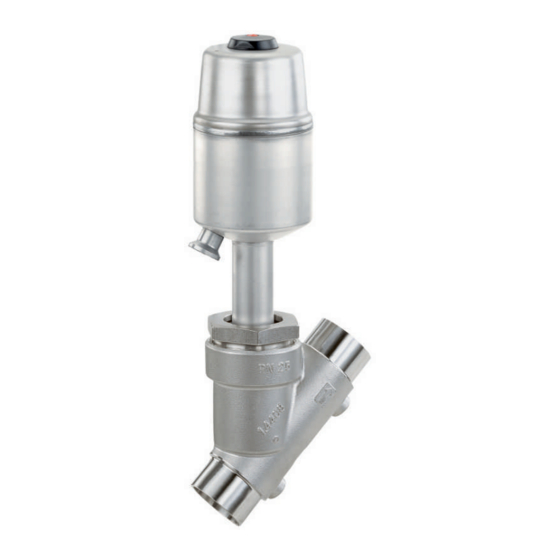
Pneumatically operated angle seat globe valve
Hide thumbs
Also See for 550:
- Installation, operating and maintenance instructions (44 pages) ,
- Assembly instructions manual (16 pages) ,
- Installation, operating, & maintenance instructions (44 pages)

Related Manuals for GEM 550


Summary of Contents for GEM 550
- Page 1 GEMÜ 550 Pneumatically operated angle seat globe valve Operating instructions further information webcode: GW-550...
- Page 2 All rights including copyrights or industrial property rights are expressly reserved. Keep the document for future reference. © GEMÜ Gebr. Müller Apparatebau GmbH & Co. KG 03.06.2022 GEMÜ 550 2 / 46 www.gemu-group.com...
-
Page 3: Table Of Contents
Description ..........Function ............ Control function ........Flow direction ........... Vent hole in the actuator ......Product label ..........4 GEMÜ CONEXO ............ 5 Correct use ............6 Order data ............7 Technical data ............. Medium ............ Temperature ..........Pressure ........... -
Page 4: General Information ............................................. 4 16 Removal From Piping
– Lists 1.3 Definition of terms Danger - corrosive materials Working medium The medium that flows through the GEMÜ product. Control function The possible actuation functions of the GEMÜ product. Control medium The medium whose increasing or decreasing pressure causes the GEMÜ... -
Page 5: Product Description
15. Consult the nearest GEMÜ sales office. page 41)"). 3.2 Description The GEMÜ 550 2/2-way angle seat globe valve has a low- maintenance stainless steel piston actuator and is pneumatic- ally operated. The valve spindle is sealed by a self-adjusting www.gemu-group.com 5 / 46 GEMÜ... -
Page 6: Function
The flow direction is indicated by an arrow on the valve body. 2/2-way body 2/2-way body under the seat over the seat Angle valve body Angle valve body under the seat over the seat Over the seat Under the seat (code M) (code G) GEMÜ 550 6 / 46 www.gemu-group.com... -
Page 7: Product Label
Traceability number Consecutive number The month of manufacture is encoded in the traceability num- ber and can be obtained from GEMÜ. The product was manu- factured in Germany. The operating pressure stated on the product label applies to a media temperature of 20 °C. The product can be used up to the maximum stated media temperature. -
Page 8: Correct Use
The product is designed for installation in piping systems and for controlling a working medium. 1. Use the product in accordance with the technical data. 2. Note the supplement acc. to ATEX 3. Please note the flow direction on the valve body. GEMÜ 550 8 / 46 www.gemu-group.com... -
Page 9: Order Data
Clamp Ra ≤ 0.4 μm (15 μinch) for media wetted surfaces, 1909 Clamp ASME BPE, in accordance with DIN 11866 H4, ASME BPE SF1 face-to-face dimension FTF ASME BPE mechanically polished internal www.gemu-group.com 9 / 46 GEMÜ 550... - Page 10 6 Seat seal PTFE 7 Control function Normally closed (NC) 8 Actuator version Actuator size 1G1 9 Type of design Without 10 Special version Certified to DIN EN 161, class A 11 CONEXO Without GEMÜ 550 10 / 46 www.gemu-group.com...
-
Page 11: Technical Data
All pressures are gauge pressures. When the flow is over the seat (M), there may be the danger of water ham- mer with liquid media! For max. operating pressures the pressure/temperature correlation must be observed. www.gemu-group.com 11 / 46 GEMÜ 550... - Page 12 All pressures are gauge pressures. When the flow is over the seat (M), there may be the danger of water ham- mer with liquid media! For max. operating pressures the pressure/temperature correlation must be observed. Pressure rating: PN 16 GEMÜ 550 12 / 46 www.gemu-group.com...
- Page 13 DN 20 Operating pressure [bar] 4 – 8 bar DN 50 DN 40 DN 32 Operating pressure [bar] 5 – 8 bar DN 80 DN 65 DN 50 DN 40 DN 32 Operating pressure [bar] www.gemu-group.com 13 / 46 GEMÜ 550...
- Page 14 5 – 8 bar DN 50 DN 40 DN 32 DN 25 DN 20 DN 15 Operating pressure [bar] 5 – 8 bar DN 50 DN 40 DN 32 DN 25 DN 20 Operating pressure [bar] GEMÜ 550 14 / 46 www.gemu-group.com...
- Page 15 0, 16, 17, 59, 25.0 20.6 18.7 17.1 15.8 14.8 17, 59, 60 25.0 21.2 19.3 17.9 16.8 15.9 * max. temperature 140 °C All pressures are gauge pressures. The valves may be used to -10 °C www.gemu-group.com 15 / 46 GEMÜ 550...
-
Page 16: Product Conformity
7.4 Product conformity Food: Regulation (EC) No. 1935/2004* Regulation (EC) No. 10/2011* FDA* * depending on version and/or operating parameters Pressure Equipment Dir- 2014/68/EU ective: Machinery Directive: 2006/42/EC GEMÜ 550 16 / 46 www.gemu-group.com... - Page 17 7 Technical data Gas: EN 161 EN 16678 Gas identification: Valve group: 2 Valve class: A Explosion protection: ATEX (2014/34/EU) on request www.gemu-group.com 17 / 46 GEMÜ 550...
-
Page 18: Mechanical Data
0.50 2.50 0.63 0.50 0.35 0.65 3.10 0.63 0.90 0.75 1.00 4.60 1.08 1.10 0.98 1.30 5.10 1.28 1.80 1.70 1.80 7.20 2.07 3.40 3.20 3.40 3.69 4.20 4.10 4.40 4.60 Weights in kg GEMÜ 550 18 / 46 www.gemu-group.com... -
Page 19: Dimensions
G 1/8 84.0 M 16 x 1 28.0 G 1/4 104.0 M 22 x 1.5 32.0 G 1/4 135.0 M 22 x 1.5 41.0 G 1/4 Dimensions in mm H max*: dependent on nominal size www.gemu-group.com 19 / 46 GEMÜ 550... -
Page 20: Installation Dimensions
M 90 x 2.0 295.0 M 105 x 2.0 312.0 Dimensions in mm The specified dimensions refer to control function 1 (normally closed NC). The dimensions are smaller for control function 2 (normally open NO). GEMÜ 550 20 / 46 www.gemu-group.com... - Page 21 264.0 291.0 M 72 x 2.0 233.0 271.0 298.0 Dimensions in mm The specified dimensions refer to control function 1 (normally closed NC). The dimensions are smaller for control function 2 (normally open NO). www.gemu-group.com 21 / 46 GEMÜ 550...
-
Page 22: Body Dimensions
Code 17: Spigot EN 10357 series A (formerly DIN 11850 series 2)/DIN 11866 series A Code 59: Spigot ASME BPE Code 60: Spigot ISO 1127/EN 10357 series C/DIN 11866 series B 2) Valve body material Code 40: 1.4435 (F316L), forged body GEMÜ 550 22 / 46 www.gemu-group.com... - Page 23 Code 17: Spigot EN 10357 series A (formerly DIN 11850 series 2)/DIN 11866 series A Code 37: Spigot SMS 3008 Code 59: Spigot ASME BPE Code 60: Spigot ISO 1127/EN 10357 series C/DIN 11866 series B 2) Valve body material Code 34: 1.4435, investment casting www.gemu-group.com 23 / 46 GEMÜ 550...
- Page 24 Code 17: Spigot EN 10357 series A (formerly DIN 11850 series 2)/DIN 11866 series A Code 37: Spigot SMS 3008 Code 59: Spigot ASME BPE Code 60: Spigot ISO 1127/EN 10357 series C/DIN 11866 series B 2) Valve body material Code 37: 1.4408, investment casting GEMÜ 550 24 / 46 www.gemu-group.com...
- Page 25 Code 17: Spigot EN 10357 series A (formerly DIN 11850 series 2)/DIN 11866 series A Code 59: Spigot ASME BPE Code 60: Spigot ISO 1127/EN 10357 series C/DIN 11866 series B 2) Valve body material Code C2: 1.4435, investment casting www.gemu-group.com 25 / 46 GEMÜ 550...
- Page 26 Dimensions in mm 1) Connection type Code 1: Threaded socket DIN ISO 228 Code 3D: Threaded socket NPT, end-to-end dimension ETE DIN 3202-4 series M8 2) Valve body material Code 37: 1.4408, investment casting GEMÜ 550 26 / 46 www.gemu-group.com...
- Page 27 Code 3C: Threaded socket Rc ISO 7-1, EN 10226-1, JIS B 0203, BS 21, end-to-end dimension ETE DIN 3202-4 series M8 Code 3D: Threaded socket NPT, end-to-end dimension ETE DIN 3202-4 series M8 2) Valve body material Code 37: 1.4408, investment casting www.gemu-group.com 27 / 46 GEMÜ 550...
- Page 28 Dimensions in mm 1) Connection type Code 1: Threaded socket DIN ISO 228 Code 3D: Threaded socket NPT, end-to-end dimension ETE DIN 3202-4 series M8 2) Valve body material Code 37: 1.4408, investment casting GEMÜ 550 28 / 46 www.gemu-group.com...
- Page 29 1/2" 65.0 19.0 G 3/4 12.0 Dimensions in mm 1) Connection type Code 9: Threaded spigot DIN ISO 228 2) Valve body material Code 37: 1.4408, investment casting Code 40: 1.4435 (F316L), forged body www.gemu-group.com 29 / 46 GEMÜ 550...
- Page 30 G 2⅜ 15.0 2½" 216.0 52.0 15.0 3" 254.0 64.0 G 3½ 18.0 Dimensions in mm 1) Connection type Code 9: Threaded spigot DIN ISO 228 2) Valve body material Code 37: 1.4408, investment casting GEMÜ 550 30 / 46 www.gemu-group.com...
- Page 31 = number of bolts 1) Connection type Code 10: Flange EN 1092, PN 25, form B, face-to-face dimension FTF EN 558 series 1, ISO 5752, basic series 1 2) Valve body material Code 37: 1.4408, investment casting www.gemu-group.com 31 / 46 GEMÜ 550...
- Page 32 Dimensions in mm n = number of bolts 1) Connection type Code 13: Flange EN 1092, PN 25, form B Code 47: Flange ANSI Class 150 RF 2) Valve body material Code 34: 1.4435, investment casting GEMÜ 550 32 / 46 www.gemu-group.com...
- Page 33 Code 86: Clamp DIN 32676 series A, face-to-face dimension FTF EN 558 series 1 Code 88: Clamp ASME BPE, face-to-face dimension FTF EN 558 series 1 2) Valve body material Code 34: 1.4435, investment casting www.gemu-group.com 33 / 46 GEMÜ 550...
- Page 34 Code 86: Clamp DIN 32676 series A, face-to-face dimension FTF EN 558 series 1 Code 88: Clamp ASME BPE, face-to-face dimension FTF EN 558 series 1 2) Valve body material Code C2: 1.4435, investment casting GEMÜ 550 34 / 46 www.gemu-group.com...
-
Page 35: Manufacturer's Information
"Technical data"). ● 4. Do not store solvents, chemicals, acids, fuels or similar CAUTION fluids in the same room as GEMÜ products and their spare parts. Hot plant components! ▶ Risk of burns. Only work on plant that has cooled ●... -
Page 36: Installation Position
(see chapters below). 14. Please note the flow direction (see chapter "Flow direc- tion"). 15. Please note the installation position (see chapter "Installa- tion position"). 10.3 Installation position The installation position of the product is optional. GEMÜ 550 36 / 46 www.gemu-group.com... -
Page 37: Installation With Threaded Sockets
3. Screw the pipe into the threaded connection of the valve body in accordance with valid standards. ð Use appropriate thread sealant. 4. Re-attach or reactivate all safety and protective devices. 10.8 Installation with flanged connection Fig. 8: Flanged connection www.gemu-group.com 37 / 46 GEMÜ 550... -
Page 38: Pneumatic Connections
+ = available Control medium connector 2 – = not available Control medium connector 2 Fig. 10: GEMÜ 550, control function 2 and 3 1. Use suitable connectors. 2. Connect the control medium lines tension-free and without any bends or knots. -
Page 39: Commissioning
CAUTION ð The product closes. Cleaning agent 2. Vent the actuator via control medium connector 4. ▶ Damage to the GEMÜ product. ð The product opens. The plant operator is responsible for selecting the clean- ● ing material and performing the procedure. -
Page 40: Troubleshooting
Tighten threaded connections / unions Sealing material faulty Replace sealing material Valve body leaking Valve body leaking or corroded Check valve body for damage, replace valve body if necessary * see chapter "Spare parts" GEMÜ 550 40 / 46 www.gemu-group.com... -
Page 41: Inspection And Maintenance
K 500… 5. Depressurize the plant or plant component. Gasket 550…SVS… 6. Actuate GEMÜ products which are always in the same po- Seat seal sition four times a year. 7. After removing / installing the GEMÜ product check that the union nut a is mechanically secured and re-tighten if necessary. -
Page 42: Removing The Actuator
6. Check parts for potential damage, replace if necessary of actuator and valve body is correct. (only use genuine parts from GEMÜ). Compare the product label of the actu- ● 15.4 Replacing the seals ator with the valve body marking. - Page 43 Returned goods can be processed only when this note is completed. If no return delivery note is included with the product, GEMÜ cannot process credits or repair work but will dispose of the goods at the operator's expense.
- Page 44 19 Declaration of Incorporation according to 2006/42/EC (Machinery Directive) Declaration of Incorporation according to the EC Machinery Directive 2006/42/EC, Annex II, 1.B for partly completed machinery Manufacturer: GEMÜ Gebr. Müller Apparatebau GmbH & Co. KG Postfach 30 Fritz-Müller-Straße 6-8 D-74653 Ingelfingen-Criesbach...
- Page 45 EN 1983, AD 2000 Note for products with a nominal size ≤ DN 25: The products are developed and produced according to GEMÜ process instructions and quality standards which comply with the requirements of ISO 9001 and ISO 14001. According to Article 4, Paragraph 3 of the Pressure Equipment Directive 2014/68/EU these products must not be identified by a CE-label.
- Page 46 GEMÜ Gebr. Müller Apparatebau GmbH & Co. KG Fritz-Müller-Straße 6-8, 74653 Ingelfingen-Criesbach, Germany Subject to alteration Phone +49 (0) 7940 1230 · info@gemue.de www.gemu-group.com 06.2022 | 88814686...