Table of Contents
Advertisement
Quick Links
Advertisement
Table of Contents

Related Manuals for Delta RTU-PD01


Summary of Contents for Delta RTU-PD01
- Page 1 PROFIBUS DP RTU-PD01 Slave Communication Module Operation Manual DVP-0215820-01...
-
Page 3: Table Of Contents
.............................4 Definition of PROFIBUS DP Port ....................4 3.2 Connecting to PROFIBUS DP Port by 35mm DIN Rail ..............4 3.3 Installing RTU-PD01 and I/O Module on DIN Rail................5 Components ............................6 Establishing PROFIBUS DP Network by RTU-PD01 ................7 Transmission Distance and Baud Rate....................7 GSD File ..............................8... -
Page 4: Introduction To Rtu-Pd01
PROFIBUS DP Slave Communicaion Module RTU-PD01 Introduction to RTU-PD01 Product Introduction 1. Thank you for choosing Delta RTU-PD01 PROFIBUS DP Slave Communication Module. To ensure correct installation and operation of the product, please read this operation manual carefully before using it. -
Page 5: Product Profile And Outline
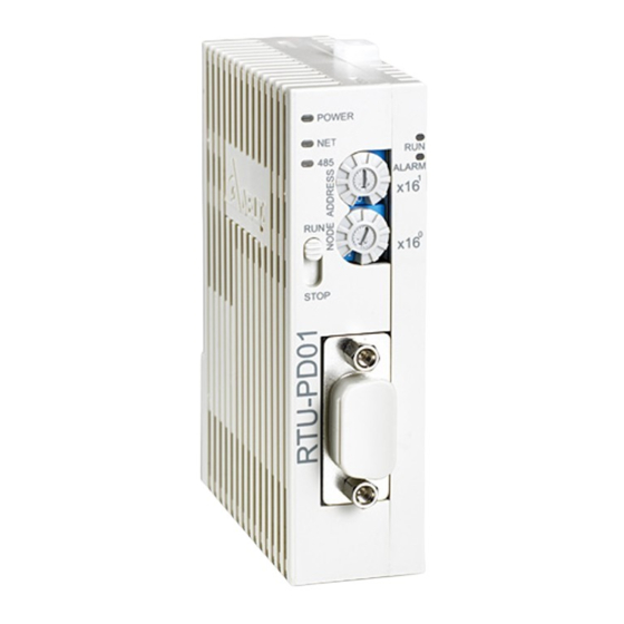
PROFIBUS DP Slave Communicaion Module RTU-PD01 Profuct Profile and Outline 2.1 Parts and Dimensions Unit: mm 1. POWER indicator 2. NET indicator 3. RS-485 indicator 4. RUN/STOP switch 5. RUN indicator 6. ALARM indicator 7. Address setup switch 8. PROFIBUS DP COM port 9. -
Page 6: Installation
Sending/receiving data N(A) 3.2 Connecting to PROFIBUS DP Port Insert PROFIBUS DP bus connector into PROFIBUS DP port on RTU-PD01 (see the figure below) Screw it tight to ensure RTU-PD01 and PROFIBUS DP bus are properly connected. DVP-PLC Operation Manual... -
Page 7: Installing Rtu-Pd01 And I/O Module On Din Rail
Open the DIN rail clips on RTU-PD01 and I/O module. Insert RTU-PD01 and I/O module on the DIN rail. Clip up the DIN rail clips on RTU-PD01 and I/O module to fix them on the DIN rail (see the figure below). -
Page 8: Components
Invalid PROFIBUS address. NET LED will flash in red H’0 or H’7E ~ H’FF color if the node address falls within this range. Example: If you need to set the node address of RTU-PD01 to 26 (decimal), simply switch x16 switch to “1” and x16 to “A”. -
Page 9: Establishing Profibus Dp Network By Rtu-Pd01
PROFIBUS DP Slave Communicaion Module RTU-PD01 Establishing PROFIBUS DP Network by RTU-PD01 The right-side interface on RTU-PD01 is connectable to DVP-Slim series special I/O modules and digital I/O modules. The RS-485 port is connectable to standard Modbus devices. See the figure below for the connection of Slim series I/O modules and Modbus devices and into the PROFIBUS DP network. -
Page 10: Gsd File
When you set up RTU-PD01 in the configuration software for PROFIBUS DP master, there will be plenty of setup items for you to choose from, which adds flexibility to the manipulation of RTU-PD01. See the figure below for RTU-PD01 settings. -
Page 11: Configuration Items
I/O module. Unit: s 8.2 Configuration Items RTU-PD01 offers every flexible configuration method when being configured in PROFIBUS DP master configuration tool, for example, you can configure digital I/O modules or special I/O modules by the actual name of the module, or self-define the cofiguration. - Page 12 PROFIBUS DP Slave Communicaion Module RTU-PD01 Configuration item Configurable device Configuration method Modbus 1 read address Modbus 2 read address Modbus 4 read address Modbus 8 read address Modbus 1 write address Modbus 2 write address Modbus devices connected to RTU-PD01...
-
Page 13: Settings Of Configuration Items
PROFIBUS DP Slave Communicaion Module RTU-PD01 Configuration item Configurable device Configuration method 1 AI 2 AI 4 AI 8 AI 1 AO Self-defined 2 AO Special I/O modules connected to RTU-PD01 configuration method 4 AO for special I/O module 8 AO... - Page 14 I/O module at the right side of Location 0 ~ 7 RTU-PD01 is 0, the second is 1 and so forth. This rule is only applicable on special I/O modules. The input channel on DVP06AD-S is set to mode 0: Voltage input -10V ~ +10V mode.
- Page 15 Value Definition The location of DVP04DA-S at the right side of RTU-PD01. The location of the first special I/O module at the right side of RTU-PD01 is Location 0 ~ 7 0, the second is 1 and so forth. This rule is only applicable on special I/O modules.
- Page 16 I/O module at the right side of Location 0 ~ 7 RTU-PD01 is 0, the second is 1 and so forth. This rule is only applicable on special I/O modules. The input channel on DVP06XA-S is set to mode 0: Voltage input -10V ~ +10V mode.
- Page 17 I/O module at the right side of Location 0 ~ 7 RTU-PD01 is 0, the second is 1 and so forth. This rule is only applicable on special I/O modules. Collecting temperature in Centigrade by CH1 ~ CH4 on Centigrade (°C)
- Page 18 I/O module at the right side of Location 0 ~ 7 RTU-PD01 is 0, the second is 1 and so forth. This rule is only applicable on special I/O modules. CH1 input mode J, K, R, S, T...
- Page 19 RTU-PD01. The location of the first special Location 0 ~ 7 I/O module at the right side of RTU-PD01 is 0, the second is 1 and so forth. This rule is only applicable on special I/O modules. DVP04AD...
- Page 20 RTU-PD01. The location of the first Location 0 ~ 7 special I/O module at the right side of RTU-PD01 is 0, the second is 1 and so forth. This rule is only applicable on special I/O modules. DVP04AD...
- Page 21 RTU-PD01. The location of the first special I/O module at the right side of Location 0 ~ 7 RTU-PD01 is 0, the second is 1 and so forth. This rule is only applicable on special I/O modules. DVP04AD...
- Page 22 PROFIBUS DP Slave Communicaion Module RTU-PD01 Parameter Value Definition Output CR number 1: 0 ~ 48 Master → Slave Output CR number 2 0 ~ 48 Output CR number 3 0 ~ 48 No. of the CR in special I/O module to be written...
- Page 23 PROFIBUS DP Slave Communicaion Module RTU-PD01 Definitions of configuration items: Parameter Value Definition Node ID 1 ~ 254 Address of Modbus device connected to RTU-PD01 Read address 1: Slave → 0 ~ 65535 Master Read address 2 0 ~ 65535 Read address 3...
- Page 24 PROFIBUS DP Slave Communicaion Module RTU-PD01 Definitions of configuration items: Parameter Value Definition Node ID 1 ~ 254 Address of Modbus device connected to RTU-PD01 Write address 1 : 0 ~ 65535 Master → Slave Write address 2 0 ~ 65535 Write address 3...
-
Page 25: Led Indicator And Trouble-Shooting
0 ~ 65535 Write address 8 0 ~ 65535 LED Indicator and Trouble-shooting There are 5 LED indicators on RTU-PD01: POWER, NET, RS-485, RUN and ALARM. POWER LED POWER LED displays whether the power supply on RTU-PD01 is working normally. LED status... - Page 26 2. Check if the I/O modules actually connected to configuration error RTU-PD01 and their order are consistent with the software configuration. RS-485 LED RS-485 LED displays whether the RS-485 communication between RTU-PD01 and the Modbus device connected is working normally. LED status Indication How to correct...
-
Page 27: Application Example 1
Exchanging data between S7-300 (Siemens PLC) and RTU-PD01 through PROFIBUS DP network Connecting RTU-PD01 to PROFIBUS DP network: 1. S7-300 as the PROFIBUS DP master; RTU-PD01 as the slave. See the PROFIBUS DP network in the figure below. 2. Set the PROFIBUS address of RTU-PD01 to “1”. - Page 28 PROFIBUS DP Slave Communicaion Module RTU-PD01 2. Select “File” => “New Project Wizard”. 3. Click “Next” in the wizard. DVP-PLC Operation Manual...
- Page 29 PROFIBUS DP Slave Communicaion Module RTU-PD01 4. Select “CPU315-2 DP” for CPU as we are using the S7-300 model. Click “Next”. 5. Select the block we need and click “Next”. DVP-PLC Operation Manual...
- Page 30 PROFIBUS DP Slave Communicaion Module RTU-PD01 6. Enter the project name and click “Finish”. 7. A new window will appear after the project is created. Add PROFIBUS DP bus 1. Select “SIMATIC 300 Station” in the project created. Double click “Hardware”, and a new window (HW-Config) will appear.
- Page 31 PROFIBUS DP Slave Communicaion Module RTU-PD01 2. In the “HW Config” window, double click “DP” in the left-hand side column and a dialog box will appear. DVP-PLC Operation Manual...
- Page 32 PROFIBUS DP Slave Communicaion Module RTU-PD01 3. Click “Properties” in the dialog box, leading to another dialog box. 4. Select “Address” in the dialog box to be the address of the master. Then Click “New” to go to the next dialog box.
- Page 33 PROFIBUS DP Slave Communicaion Module RTU-PD01 5. Select communication speed and bus type, then click “OK”. 6. Confirm the communication speed and master address for PROFIBUS DP bus, then click “OK”. DVP-PLC Operation Manual...
- Page 34 PROFIBUS DP Slave Communicaion Module RTU-PD01 7. Confirm the information on the PROFIBUS DP bus in the dialog box and click “OK”. 8. Once all the parameters are set, a PROFIBUS DP bus will appear after the UR window. DVP-PLC Operation Manual...
- Page 35 PROFIBUS DP Slave Communicaion Module RTU-PD01 Add GSD file 1. Select “Options” => “Install New GSD” in the HW Config window. 2. Find the path of the GSD file, select it and click “Install” to add the GSD file needed.
- Page 36 3. We can then see RTU-PD01 in the right-hand side column. RTU-PD01 is the module added. Add RTU-PD01 slave and set up parameters 1. Select PROFIBUS DP on the right-hand side column and double click “RTU-PD01” to open a dialog box.
- Page 37 PROFIBUS DP Slave Communicaion Module RTU-PD01 2. In the dialog box, select the address of RTU-PD01 slave. The address has to be the same as the setting of address setup switch on RTU-PD01. Click “OK”. 3. Add PROFIBUS DP bus to RTU-PD01.
- Page 38 PROFIBUS DP Slave Communicaion Module RTU-PD01 4. Select Slot 0 and double click “DVP16SP11R/T” in the right-hand side column. 5. Configure DVP16SP11R/T to Slot 0. 6. Configure other slots as configuring Slot 0. To configure, select one of the slots and double click on the items to be configured in the right-hand side column.
- Page 39 PROFIBUS DP Slave Communicaion Module RTU-PD01 7. Slot 0 and Slot 1 are for the configuration of digital I/O modules. The configuration of digital I/O modules does not require other parameter settings. When you configure digital I/O modules by self-defined method, and if the number of I/O points is less than 8, the calculation will be based on the number 8.
- Page 40 PROFIBUS DP Slave Communicaion Module RTU-PD01 9. Double click the configured Slot 3 in “HW Config” window to open the dialog box in the figure below. Refer to 8.3.3 for the definition of every parameter in this dialog box. 10. Double click the configured Slot 4 in “HW Config” window to open the dialog box in the figure below.
- Page 41 PROFIBUS DP Slave Communicaion Module RTU-PD01 11. After all the configuration items for RTU-PD01 are set, double click the RTU-PD01 slave on the PROFIBUS DP bus in “HW Config” window to open the dialog box in the figure below. Refer to 8.1 for the definition of every parameter in this dialog box.
- Page 42 PROFIBUS DP Slave Communicaion Module RTU-PD01 Data Mapping See the table below for the data mapping relations under the parameter settings. Register in S7-300 Data transmission direction Slave devices and addresses connected to master in PROFIBUS DP network RTU-PD01 QB0 bit 0 ~ bit 7...
- Page 43 Program Example When M0.0 = ON, write 1 to Y0 ~ Y7 on DVP16SP and Y0 ~ Y3 on DVP08SP connected to RTU-PD01. When M0.1 = ON, read the status on X0 ~ X7 on DVP16SP connected to RTU-PD01 to MB0, and the status on X0 ~ X3 on DVP08SP to MB1.
- Page 44 PROFIBUS DP Slave Communicaion Module RTU-PD01 MEMO DVP-PLC Operation Manual...