
Related Manuals for Emerson RSTi-OM


Summary of Contents for Emerson RSTi-OM
- Page 1 RSTi-OM IO-LINK Master Fieldbus Module with PROFINET and Modbus/TCP Quick Start Guide GFK-3213A Jun 2021...
-
Page 3: Table Of Contents
Contents Contents ....................i Introduction ................... 1 Device Description .................. 2 Features ....................3 Connectors Overview ................4 Front Panel Description ................5 IO-Link Link Connectors ................6 IO-Link Port Connectors .................. 6 Power Connectors ..................7 Network Connectors ..................8 Hardware Installation ................ -
Page 5: Introduction
Introduction The RSTi-OM Quick Start Guide covers RSTi-OM IO-Link devices. Users can expect to learn how to configure and install the IO-Link Master (IOLM) and connect to other IO-Link devices. Product name Description OMIOLM001 IO-Link Master Device Note: For IO-Link hubs & cable accessories refer to datasheet and/or user manual (00813-0100-0149). -
Page 6: Device Description
Device Description The module is a PROFINET or Modbus/TCP Fieldbus module with 8 Class A IO-Link master ports according to IO-Link standard V1.1. The Fieldbus module serves as an interface between the PROFINET controller or Modbus TCP controller Fieldbus system and IO-Link devices as well as discrete I/O in the field level. -
Page 7: Features
Features The IOLM’s web interface provides a platform so that you can easily configure, review diagnostic pages, and access advanced features, such as the ability to: • Setup Passwords for pre-defined user accounts Utilize data storage to provide automatic and manual data storage to upload or download IO-Link v1.1 device parameters •... -
Page 8: Connectors Overview
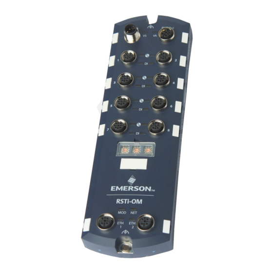
Connectors Overview Figure 1: Front Panel Connectors Connector Type Cable Description Power Supply M12 L-Code IO-Link M12 A-Code Ethernet M12 D-Code IO-LINK Master W/ PROFINET and Modbus Quick Start Guide GFK-3213A... -
Page 9: Front Panel Description
Front Panel Description Figure 2: Front Panel and Indicators IO-LINK Master W/ PROFINET and Modbus Quick Start Guide GFK-3213A... -
Page 10: Io-Link Link Connectors
IO-Link Link Connectors IO-Link Port Connectors The IOLM provides eight IO-Link ports with M12, 5-pin female/A coded connectors. Each port has robust over-current protection and short circuit protection on its L+/L- power output and C/Q IO-Link signal. The pin-out for each IO-Link port is per the IO-Link standard and is provided in the following table: This table provides signal information for the IO-Link connectors. -
Page 11: Power Connectors
Note: Power connectors must have an approved cable or protective cover attached to the port guarantee to IP67 compliance. For additional information on available connectors and protective covers, please consult the Emerson datasheet 00813-0100-0149. Pin Power Power Output or Description... -
Page 12: Network Connectors
Network Connectors The IOLM provides two Fast Ethernet (10/100BASE-TX) M12, 4-pin female D-coded connectors. Signal You can use this procedure to connect the IOLM to the network. 1. Securely connect one end of a shielded twisted-pair (Cat 5 or higher) M12 Ethernet cable to either Ethernet port. 2. -
Page 13: Hardware Installation
Hardware Installation Pre-Installation Checklist 1. Setting the Rotary Switch 2. Connecting to the Network 3. Connecting the Power 4. Mounting the IOLM IO-LINK Master W/ PROFINET and Modbus Quick Start Guide GFK-3213A... -
Page 14: Setting The Rotary Switch
Setting the Rotary Switch You can use the rotary switches under the configuration window on the IOLM to set the lower 3-digits (8 bits) of the static IP address (192.168.11.XXX). For example, the default IP address is 192.168.11.202. When the rotary switches are set to 000, the final segment of the IP address will remain at 202. - Page 15 • An emergency method to reset the IOLM to factory defaults, so that software can be used to program the appropriate IP address, and then reset the switches to 000. Note: If you set the network address using the rotary switches, the rotary switch setting overrides the network settings in the web interface when the IOLM is initially powered on or after cycling the power.
-
Page 16: Connecting The Network
The arrow points to the switch location. 0 is located at the 9:00 position. Turn the dial clockwise to the appropriate setting. 3. Close the window and make sure that it snaps shut tightly. Note: Failure to close the configuration window properly may compromise IP67 integrity. -
Page 17: Connecting The Power
Connecting the Power You can use the following procedure to connect the IOLM to a power supply. CAUSTION Note: Power should be disconnected from the power supply before connecting it to the IOLM. Otherwise, your screwdriver blade can inadvertently short your power supply terminal connections to the grounded enclosure. -
Page 18: Mounting The Iolm
a. The VS LED lights. b. The ETH1/ETH2 LED lights on the connected port. The MOD and NET LEDs are lit. d. The IO-Link LEDs flash (if no IO-Link device attached) or are lit if an IO-Link device is attached. Note: It takes approximately 25 seconds after power-up for the IO-Link Master to be ready for operation. - Page 19 Figure 4: Mounting the IOLM 8 PNIO L IO-LINK Master W/ PROFINET and Modbus Quick Start Guide GFK-3213A...
-
Page 20: Iolm Configuration
Note: The following pages will provide a brief description of configuring the module with a PROFINET controller. For more detailed information on configuration over Modbus TCP, OPC-UA or MQTT, please consult GFK- 3212, RSTi-OM User Manual. IO-LINK Master W/ PROFINET and Modbus Quick Start Guide GFK-3213A... - Page 21 Figure 5: Adding the IOLM to the Controller The PROFINET device will then added under the PROFINET controller or PROFINET section of the CPE. For more information, consult the RSTi-OM User Manual (GFK-3212). IO-LINK Master W/ PROFINET and Modbus Quick Start Guide...
- Page 22 Installing the GSDML File Note: GSDML files are available at Emerson’s support site. Please see the links provided at the end of this document. 1. Launch PAC Machine Edition. 2. From the Navigator, right-click on the PROFINET or PNC in the Hardware Configuration of the controller section and select Add IO-Device.
- Page 23 3. Navigate to the folder where the GSDML for IOLM is located, select the GSDML-xxxx.zip and click on Open. Figure 7: PROFINET Device Catalog IO-LINK Master W/ PROFINET and Modbus Quick Start Guide GFK-3213A...
- Page 24 IP Address Configuration RSTi-OM IOLM gateways support three methods for IP address assignment according to GSDML Specification. • DCP - The IOLM supports IP address assignment via Discovery and basic Configuration Protocol (DCP). See Section Assigning an IP Address via IO Controller (DCP) of GFK-3212 for procedures.
- Page 25 For detailed information, please consult Section Device Name Assignment of the RSTi-OM User Manual (GFK-3212). Setting the IO Device Update Time The PROFINET device Update Rate can be set in the Inspector window of the PAC Machine Edition. The unit of update rate is in milli-seconds. The allowable rates are 8, 16, 32, 64, 128, 256, and 512.
- Page 26 IOLM module in the Hardware configuration and select Change Module List. For more information on the Configuration of IO-Link Ports, please consult Section Configuring Link Ports of the RSTi-OM User Manual (GFK-3212). PROFINET IO Configuration For detailed instructions, PROFINET IO Reference Information of the RSTi- OM User Manual (GFK-3212).
-
Page 27: Web Interface
Web Interface The IOLM module’s settings can be adjusted using the web interface. To access the interface, open a web browser and enter the IOLM’s IP address. Note: The IOLM default IP address is: 192.168.11.202 and the subnet mask is 255.255.255.0. You may need to change your laptop’s or PC’s IP address range to access the IOLM web interface. -
Page 28: Additional Information
Additional Information User manuals, product updates, and other information sources are available on the Support website: https://www.emerson.com/en-us/support RSTI-OM User Manual GFK-3212 RSTi-OM Secure Deployment Guide GFK-2222 IO-LINK Master W/ PROFINET and Modbus Quick Start Guide GFK-3213A... -
Page 29: General Contact Information
All Rights Reserved. We reserve the right to modify or improve the designs or specifications of the products mentioned in this manual at any time without notice. Emerson does not assume responsibility for the selection, use, or maintenance of any product.