
Related Manuals for Emerson PACSystems RX3i IEC 61850


Summary of Contents for Emerson PACSystems RX3i IEC 61850
- Page 1 USER MANUAL GFK-2849A Oct 2019 PACSystems RX3i IEC 61850 ETHERNET COMMUNICATION MODULE USER MANUAL...
-
Page 2: Table Of Contents
User Manual Contents GFK-2849A Oct 2019 Contents Chapter 1: Introduction ............1 Description ......................2 Specifications ...................... 4 Controls and Indicators ..................5 1.3.1 Secure Digital (SD) Card Slot ..............5 1.3.2 Switched {XE Switch} Ethernet {XE Ethernet} Ports {XE Ports} ....5 1.3.3 Port Status Indicators ................ - Page 3 User Manual Contents GFK-2849A Oct 2019 Ethernet Port Connections................. 20 2.7.1 IEC 61850 Network Connections ............. 21 2.7.2 RJ-45 Port Connections................21 2.7.3 Installing Small Form-factor Pluggable (SFP) Devices ....... 21 2.7.4 Removing SFP Devices................22 Powerup Indicator LED Patterns ................. 23 2.8.1 Detailed Indicator LED Descriptions ............
- Page 4 User Manual Contents GFK-2849A Oct 2019 3.5.4 Download and Upload of ECM850 Configuration to/from the RX3i Controller .................. 60 IEC 61850 Configurator - Scenarios and Techniques .......... 61 3.6.1 Exporting complete configurations ............61 3.6.2 Importing Configuration from a File ............63 3.6.3 Configuration Scenarios for IEC 61850 Configurator ........
- Page 5 User Manual Contents GFK-2849A Oct 2019 4.7.1 Configuring SNTP for ECM850 ..............96 4.7.2 SNTP Operation ..................97 4.7.3 Multiple SNTP Servers in a Network ............97 4.7.4 Loss or absence of SNTP Timing Signals ........... 97 Hot Standby (HSB) Operation for ECM850 ............97 4.8.1 Basic HSB System Overview ..............
- Page 6 User Manual Contents GFK-2849A Oct 2019 Methodology ....................121 Appendix C: Protocol Implementation Conformance Statements (PICS) ..............123 General ......................123 ASCI Basic Conformance Statement..............123 ACSI Models Conformance Statement ............. 124 ACSI Service Conformance Statement ............. 125 Appendix D: Model Implementation Conformance Statement (MICS) ..............
- Page 7 Changes, modifications, and/or improvements to equipment and specifications are made periodically and these changes may or may not be reflected herein. It is understood that Emerson may make changes, modifications, or improvements to the equipment referenced herein or to the document itself at any time.
-
Page 8: Chapter 1: Introduction
Oct 2019 Chapter 1: Introduction This chapter introduces the PACSystems RX3i IEC 61850 Ethernet Communication Module, or ECM850 for short. The final pages of this chapter are a glossary that define many of the terms and acronyms used in the manual. -
Page 9: Description
Associated Information Exchange: www://tc57.iec.ch/ Description The PACSystems RX3i IEC 61850 Ethernet Communication Module, catalog number IC695ECM850, or ECM850, connects a PACSystems RX3i controller to an IEC 61850 network, enabling the controller to act as an IEC 61850 Client and communicate with... - Page 10 User Manual Chapter 1 GFK-2849A Oct 2019 Features of the ECM850 include: • Supports the following IEC 61850 client features Multiple connections to IEDs — Read and write of data values — Control model – all models — Report by exception – reporting buffered and un-buffered —...
-
Page 11: Specifications
User Manual Chapter 1 GFK-2849A Oct 2019 Specifications ECM850 Specifications Protocol Support IEC 61850 Client as per PICs and MICs specifications CPU Compatibility RX3i CPUs with firmware version 8.05 or higher (CRU320, CPU320, CPU315, CPE305, CPE310) PAC Machine Edition Compatibility Machine Edition 8.0 SIM 7 Power Requirements 3.3V:... -
Page 12: Controls And Indicators
User Manual Chapter 1 GFK-2849A Oct 2019 “PLC Protocol Variables” is defined as the set of RX3i controller variables which represent the IEC 61850 protocol data attributes in a structured format in a variable list. This typically includes the additional variables which are required to perform “WRITE” operations to an IED. See section 3.3.9 Generate PLC Protocol Variables (PPVs) for each ECM850, for more details. -
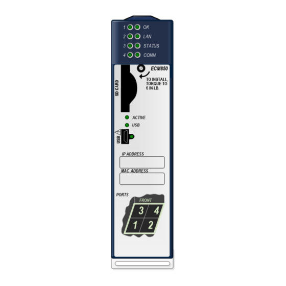
Page 13: Port Status Indicators
User Manual Chapter 1 GFK-2849A Oct 2019 The ECM850 connects to an IEC 61850 network by means of one or more of its four switched external Ethernet ports. Two 8-conductor RJ-45 shielded twisted pair 10/100/1000 Mbps copper interfaces and two Small Form-factor Pluggable (SFP) cages provide flexibility in media selection. -
Page 14: Micro Usb Port {Xe Micro Usb Port
– BASE-T CAT5e/ (maximum) CAT6 Emerson part number IC695SPF002 Emerson part number IC695SPC100 1.3.5 Micro USB Port {XE Micro USB Port} The ECM850 has a USB Micro-B socket for connection to a computer running Windows Vista or Windows 7. The USB port can be used to access the ECM850’s Command Line Interface (CLI) function using a terminal emulation application such as HyperTerminal. -
Page 15: Iec 61850 Networks For Pacsystems
User Manual Chapter 1 GFK-2849A Oct 2019 1, 2, 3, 4 Indicate link speed, link connection and link activity corresponding to the four external Ethernet ports. IEC 61850 Networks for PACSystems IEC 61850 is an international standard for the design of electrical substation automation that defines the communication between electrical switchgear and substation control equipment. -
Page 16: Basic System: One Rx3I Cpu And One Ecm850 Using A Single Port
PACSystems RX3i CPU node having one ECM850, and one IEC 61850 network with three Emerson IEDs and one third-party IED. Up to 32 IEDs can be installed on a single RX3i IEC 61850 network. -
Page 17: Basic System: One Rx3I Cpu And Ecm850 Using Multiple Ports
User Manual Chapter 1 GFK-2849A Oct 2019 Figure 5: RX3i CPU with one ECN850 and One IEC61850 Network and three IED’s 1.5.1 Basic System: One RX3i CPU and ECM850 Using Multiple Ports The illustration below shows the same basic system as before, with one RX3i CPU with one ECM850 acting as an IEC 61850 client on a single IEC 61850 network, but this example shows the ECM850 directly connected to each separate IED in a star topology. -
Page 18: Systems With One Rx3I Cpu And Two Ecm850S
User Manual Chapter 1 GFK-2849A Oct 2019 1.5.2 Systems with One RX3i CPU and Two ECM850s Both examples in this section show systems with one RX3i CPU that has two ECM850s. The IEC 61850 network can serve up to 128 IEDs (in star topology). Note that multiple ECM850s in the same rack are not synchronized such that all ECM850s are guaranteed to power up at the same time. -
Page 19: One Rx3I Cpu With Four Ecm850S On Separate Networks
User Manual Chapter 1 GFK-2849A Oct 2019 1.5.3 One RX3i CPU with Four ECM850s on Separate Networks This example shows a system with one RX3i CPU node containing the maximum of four ECM850s, with each ECM850 connected to a different network. In this architecture, up to 128 IEDs are allowed, spread across the four networks. -
Page 20: Glossary
Central Processing Unit. In the context of this manual, CPU refers to an RX3i controller CPU Node In a PACSystems RX3i IEC 61850 network, a CPU Node is a node that has a PACSystems RX3i CPU in its rack and is connected to the IEC 61850 network. Data Attribute... - Page 21 Substation Configuration description Language (SCL) as defined in IEC 61850-6 Small Form-factor Pluggable. Pluggable, hot-swappable Ethernet transceivers. SRTP Service Request Transport Protocol, an Ethernet-based client-server protocol that allow clients to read and write system memory of SRTP-capable Emerson devices Status Bits Module status data in RX3i CPU reference memory.
-
Page 22: Chapter 2: Installation
As the consignee, it is your responsibility to register a claim with the carrier for damage incurred during shipment. Emerson will fully cooperate with you, however, should such action be necessary. -
Page 23: Installation In Hazardous Areas
User Manual Chapter 2 GFK-2849A Oct 2019 at least a pollution degree 2 environment. For details about installing RX3i rack systems, refer to GFK-2314, PACSystems RX3i System Manual. Installation in Hazardous Areas The following information is for products bearing the UL marking for Hazardous Areas or ATEX marking for explosive atmospheres: CLASS 1 DIVISION 2 GROUPS ABCD •... -
Page 24: Removing The Backplane Knockout
User Manual Chapter 2 GFK-2849A Oct 2019 2.4.1 Removing the Backplane Knockout The ECM850 must be installed in the main (CPU) rack of an RX3i system, using a Universal Backplane such as IC695CHS007, CHS012 or CHS016. The back of the ECM850 has an exposed heat sink and backplane connector. Before inserting the module into the backplane, remove the plastic knockout in the slot where the module will be placed. -
Page 25: Module Removal
User Manual Chapter 2 GFK-2849A Oct 2019 • Insert the two provided M3x5 machine screws through the module’s bottom bracket into threaded holes in the bottom of the backplane and screw them several turns using a #1 Phillips screwdriver, but do not tighten. •... -
Page 26: Fault Notifications
User Manual Chapter 2 GFK-2849A Oct 2019 WARNING Inserting or removing a module with power applied to the system may cause an electrical arc. This can result in unexpected and potentially dangerous action by field devices. Arcing is an explosion risk in hazardous locations. Be sure that the area is non-hazardous or remove system power appropriately before removing or inserting a module. -
Page 27: Next Steps
User Manual Chapter 2 GFK-2849A Oct 2019 Figure 14 Next Steps The full configuration of the ECM850 is covered in detail in the following chapters of this manual, but in brief, the steps are the following: Add the ECM850 to the RX3i Target Hardware Configuration. Select the slot in which the ECM850 is installed, right-click and select Add Module. -
Page 28: Iec 61850 Network Connections
User Manual Chapter 2 GFK-2849A Oct 2019 Figure 15 2.7.1 IEC 61850 Network Connections Connections to the ECM850 can be made using standard cables. Each ECM850 can be connected to only one IEC 61850 network. Different devices on the same LAN, however, can be connected via more than one port. -
Page 29: Removing Sfp Devices
User Manual Chapter 2 GFK-2849A Oct 2019 Figure 16 WARNING Optical SFPs use an invisible laser to generate a fiber-optic signal. Always keep the port covered when a cable is not installed. DO NOT look into the open port if a cable is not installed. -
Page 30: Powerup Indicator Led Patterns
User Manual Chapter 2 GFK-2849A Oct 2019 Powerup Indicator LED Patterns At powerup, the indicator LEDs show the blink patterns described below. The LEDs also blink diagnostic patterns for certain operating errors and for module identification. See “Chapter 5:, Diagnostics” for a description of the blink patterns. Step LED/ Blink pattern Description... - Page 31 User Manual Chapter 2 GFK-2849A Oct 2019 No network activity STATUS LED The STATUS LED indicates the condition of the ECM850 during normal operation. It indicates whether an entry other than the startup event is present in the module’s local log. STATUS can also indicate whether any of the MAC addresses are invalid.
-
Page 32: Installing The Usb Port Driver
User Manual Chapter 2 GFK-2849A Oct 2019 Port LEDs The ECM850 has four Port Indicator LEDs, 1, 2, 3, and 4 that indicate link speed, link connection and link activity corresponding to the four possible external Ethernet ports. Blue, ON Link connected, 1000 Mbps Blue, blinking Port active, 1000 Mbps... -
Page 33: Firmware Updates
User Manual Chapter 2 GFK-2849A Oct 2019 2.10 Firmware Updates The Winloader utility is used to update the firmware on an ECM850. The current firmware version of the ECM850 may be obtained using either the Machine Edition programmer (Online Commands->Show Status->Details), or the module’s Command Line Interface node command. -
Page 34: Chapter 3: Configuration
User Manual Chapter 3 GFK-2849A Oct 2019 Chapter 3: Configuration This chapter explains procedure to configure an ECM850 with IEC 61850 client system, and also explains how to add IEDs and select PPVs for monitoring and control in RX3i controller applications. -
Page 35: Non-Volatile Configuration Parameters
User Manual Chapter 3 GFK-2849A Oct 2019 3.2.1 Non-Volatile Configuration Parameters Parameter Default Value IP Address 0.0.0.0 Subnet Mask 0.0.0.0 Default Gateway 0.0.0.0 Device Name Basic Configuration Steps 3.3.1 Add one or more ECM850s In the Project tab of the Navigator, expand the Hardware Configuration and the main rack. -
Page 36: Configure Each Ecm850 Parameters (Settings Tab)
User Manual Chapter 3 GFK-2849A Oct 2019 3.3.2 Configure each ECM850 Parameters (Settings Tab) Edit ECM850 parameters in the Settings Tab as appropriate. Figure 19 The parameters are described below: IP Address ECM850’s IP address. Default is 0.0.0.0 CAUTION If the IP Address is set such that its domain is different that the IP addresses of the IEDs (as set in “IEC 61850 Configurator”), then module will be unable to communicate on the network and might disrupt network communications. - Page 37 User Manual Chapter 3 GFK-2849A Oct 2019 CAUTION If the gateway is improperly set, devices may be unable to communicate on the network, disrupting network communications. Contact your network administrator to assign values that work with an existing network. Network Time Synch Network Time Synchronization mode which user can select.
-
Page 38: Open Iec 61850 Configurator For Each Ecm850
User Manual Chapter 3 GFK-2849A Oct 2019 Figure 21 ECM850 (Power Consumption Tab) The Power consumption tab provides details of the power consumption of the ECM850. Figure 22 3.3.3 Open IEC 61850 Configurator for each ECM850 Right click on ECM850 in which you want to configure IEC 61850 Client system and choose Configure IEC 61850 Client. -
Page 39: Add Ieds To Each Ecm850
User Manual Chapter 3 GFK-2849A Oct 2019 This opens a model dialogue as an Integrated “IEC 61850 Configurator”, which provides the required user interface for protocol specific configuration of IEC 61850 Client. Figure 24 Note The “IEC 61850 Configurator” cannot be opened when Machine Edition is online with the RX3i controller. - Page 40 User Manual Chapter 3 GFK-2849A Oct 2019 Figure 26 The new server device will appear under IEC 61850 Client. Figure 27 Configuration...
-
Page 41: Configure Each Ied Parameters
User Manual Chapter 3 GFK-2849A Oct 2019 3.3.5 Configure each IED parameters Select Server device in the IEC 61850 Configurator, to get the server device parameters in right window pane. Under right window pane, configure Server device parameters as per definitions given below. - Page 42 User Manual Chapter 3 GFK-2849A Oct 2019 Calling AP Title This setting is according to ISO 8650-1(ACSE) and should not be used in standard cases. The default value is 1.1.1.999 Calling AE Qualifier This setting is according to ISO 8650-1(ACSE) and should not be used in standard cases. The default value is 12 Called AP Title This setting is according to ISO 8650-1(ACSE) and should not be used in standard cases.
-
Page 43: Read Variables Of Each Ied
User Manual Chapter 3 GFK-2849A Oct 2019 In a Report Control Block (RCB), the data are pushed by the server on a trigger. The trigger support several options: • TrgOp data-change The enabling of this option will ensure that data will be available on Data value change. - Page 44 User Manual Chapter 3 GFK-2849A Oct 2019 Read variables from SCL file for each IED Online configuration: Read variables from server for each IED Configuration...
- Page 45 User Manual Chapter 3 GFK-2849A Oct 2019 Read variables from SCL file for each IED Right click on Server device in the IEC 61850 Configurator and choose Read variables from SCL file. Figure 29 In the Open dialogue box that appears, browse and select SCL ( .icd or .cid) file for the Server device and click Open.
- Page 46 User Manual Chapter 3 GFK-2849A Oct 2019 Figure 31 A pop up Read variables from server appears, showing Query is running… (x logical nodes received). Click Cancel to cancel this operation. Figure 32 In the dialogue box that appears, <server name>: Select variables displays the IEC 61850 data model for the IED.
- Page 47 User Manual Chapter 3 GFK-2849A Oct 2019 Figure 33 Note Be sure to set the IP Address of the IED correctly and ensure that Machine Edition is connected over the network Configuration...
-
Page 48: Select Variables For Each Ied
User Manual Chapter 3 GFK-2849A Oct 2019 3.3.7 Select Variables for Each IED In the dialogue box that appears, <server name>: Select variables allows selection of variables by means of check boxes. Figure 34 Click OK, to import selected variables under Server device or click Cancel to cancel import of variables. -
Page 49: Validate Configuration Of Iec 61850 Client For Each Ecm850
User Manual Chapter 3 GFK-2849A Oct 2019 3.3.8 Validate Configuration of IEC 61850 Client for each ECM850 In the IEC 61850 Configurator window, right click on IEC 61850 Client and choose Validate Configuration. Figure 36 In the bottom pane messages appear, indicating results of validation. The messages provide details of variable configuration information as defined below. - Page 50 User Manual Chapter 3 GFK-2849A Oct 2019 Total Devices The total number of IEC 61850 Server devices (IEDs) added to the configuration. Input Variables The total number of attributes which are of Input type. These are attributes which are “Read only”...
-
Page 51: Generate Plc Protocol Variables (Ppvs) For Each Ecm850
User Manual Chapter 3 GFK-2849A Oct 2019 3.3.9 Generate PLC Protocol Variables (PPVs) for each ECM850 In the IEC 61850 Configurator window, click on cross button X to close the Configurator. A pop up showing a message “Creating ECM module Protocol variables...” appears, showing that PPVs are being generated in the project for the ECM850. -
Page 52: Advanced Configuration For Iec 61850 Client
User Manual Chapter 3 GFK-2849A Oct 2019 If the ECM850 cannot connect to an IED, the ECM850 logs a Loss of Device fault in its local log table and provides the information to the RX3i CPU controller fault tables. The ECM850 periodically attempts to establish communications with IED. -
Page 53: Configuring Urcbs
User Manual Chapter 3 GFK-2849A Oct 2019 They are stored (up to the specified limit for each server) in case communication between server and client fails. The client asks for buffered reports only if it detects a connection failure or lost report, otherwise the BRCBs act like URCBs and the server sends a block immediately after a value or quality change. - Page 54 User Manual Chapter 3 GFK-2849A Oct 2019 Configuring URCBs – Direct Method Add IED. Read variables from the server, select IEC 61850 variables of required RCB - Logical Node: LLN0 and Data Object: <report name><report number>. Figure 40 Right click on the server device in the IEC 61850 Configurator and choose RCB Assignment.
- Page 55 User Manual Chapter 3 GFK-2849A Oct 2019 Figure 41 In the dialogue box that appears <server name> RCB Assignment, click Add and name the IEC target as “VXTARGET”. Figure 42 In the dialogue box <server name> RCB Assignment, Click Import to get the reports from the IEC 61850 Server device.
- Page 56 User Manual Chapter 3 GFK-2849A Oct 2019 Figure 43 In the dialogue box <server name> RCB Assignment, Click Add and select the required Report [<server name>/LLN0/<report name><report number>[RP]<report name>] from the drop-down menu. Figure 44 Click Add to add multiple reports. Configuration...
- Page 57 User Manual Chapter 3 GFK-2849A Oct 2019 Figure 45 11. In the dialogue box <server name> RCB Assignment, click OK to close. 12. In the IEC 61850 Configurator window, right click on IEC 61850 Client and choose Validate Configuration. If there are no errors, you can proceed to the next step. Figure 46 Note: Set the IP Address of IEC 61850 Server device correctly and ensure that machine edition is...
- Page 58 User Manual Chapter 3 GFK-2849A Oct 2019 13. In the dialogue box <server name> RCB Assignment, click OK to close. On closure of the IEC 61850 Configurator, required PPVs are generated automatically in the project. This is shown in the screenshot below, where report-related parameters are shown as variables.
- Page 59 User Manual Chapter 3 GFK-2849A Oct 2019 ConfRev_RP Configuration revision parameter for the report. Dataset_RP Dataset, as a string data array type with a limit of 32 elements. GI_RP General Interrogation” parameter for the report. IntgPd_RP Integrity period shows the time period for the “Integrity poll” of data objects. OptFlds_RP Optional fields, per the IEC 61850 specifications on which the report is functioning.
-
Page 60: Configuring Brcbs
User Manual Chapter 3 GFK-2849A Oct 2019 3.4.3 Configuring BRCBs You can right click on the server and “RCB assignment” for configuring a Buffered RCB or statically assigned RCB. You can directly import from a server or enter the name of the RCB in appropriate format. - Page 61 User Manual Chapter 3 GFK-2849A Oct 2019 Right click on Server device in the IEC 61850 Configurator and choose RCB Assignment. Figure 50 In the dialogue box that appears <server name> RCB Assignment, click Add and name the IEC target as “VXTARGET”. Figure 51 Configuration...
- Page 62 User Manual Chapter 3 GFK-2849A Oct 2019 In the dialogue box <server name> RCB Assignment, Click Import to get the reports from the IEC 61850 Server device A pop up Read variables from server appears, showing Query is running … (x logical nodes received).
- Page 63 User Manual Chapter 3 GFK-2849A Oct 2019 Click Add to add multiple reports. Figure 54 In the dialogue box <server name> RCB Assignment, click OK to close. 10. In the IEC 61850 Configurator window, right click on IEC 61850 Client and choose Validate Configuration.
- Page 64 User Manual Chapter 3 GFK-2849A Oct 2019 11. In the dialogue box <server name> RCB Assignment, click OK to close. On closure of the IEC 61850 Configurator, all required PPVs are generated automatically in the project. This is shown in the screenshot below, where report-related parameters are shown as variables.
- Page 65 User Manual Chapter 3 GFK-2849A Oct 2019 Reports-related Parameters for URCB • BufTm_BR This is buffer time parameter for report. • ConfRev_BR This is a Configuration revision parameter for the configured report. • Dataset_BR This provides the name of Dataset as a string data type in array. The limit is 32 elements.
-
Page 66: Configuring Originator Category For Ecm850
User Manual Chapter 3 GFK-2849A Oct 2019 3.4.4 Configuring Originator Category for ECM850 The “orCat” is defined in the “IEC 61850 Configurator” dialogue in Machine Edition. (Default = Station control). In the IEC 61850 Configurator window, click on IEC 61850 Client. In the right pane of the Configurator window, double click on Originator category (orCat) and select the required category type. -
Page 67: Configuration Features For The Ecm850
User Manual Chapter 3 GFK-2849A Oct 2019 Configuration Features for the ECM850 This section describes features for handing ECM850 configuration in a Machine Edition project. 3.5.1 Configuring Multiple Modules and Multiple Devices You can configure multiple ECM805 modules in an RX3i target, up to four. Each ECM850 can be configured to connect with multiple IEDs, not exceeding 32 devices. -
Page 68: Copy, Paste, And Movement Of Ecm850S Within A Target
User Manual Chapter 3 GFK-2849A Oct 2019 The PPVs from each ECM850 are identified by a ‘Slot Number prefix’ followed by an underscore. This is shown below. Figure 60 3.5.2 Copy, Paste, and Movement of ECM850s Within a Target Machine Edition supports copy and paste of an ECM850 within a target across different slots. The drag and drop option is also available for the ECM850. -
Page 69: Iec 61850 Configurator - Scenarios And Techniques
User Manual Chapter 3 GFK-2849A Oct 2019 IEC 61850 Configurator - Scenarios and Techniques This section describes the different scenarios for configuration using the “IEC 61850 Configurator” and also details of techniques for exporting and importing IEC 61850 configurations. 3.6.1 Exporting complete configurations The “IEC 61850 Configurator”... - Page 70 User Manual Chapter 3 GFK-2849A Oct 2019 In the dialogue box that appears Export Assistance, select Export a complete project (XML) and click Next. Figure 62 In the dialogue box Save As, browse to the required path, name the export file and click Save.
-
Page 71: Importing Configuration From A File
User Manual Chapter 3 GFK-2849A Oct 2019 Note: This is the recommended option for exporting a configuration from “IEC 61850 Configurator”. Do not use the ‘Export some project (XML) option. 3.6.2 Importing Configuration from a File A configuration saved in an XML file (schema as exported by the export tool) can be imported into the IEC 61850 Configurator. - Page 72 User Manual Chapter 3 GFK-2849A Oct 2019 Figure 66 CAUTION If you corrupt the XML file contents and attempt to import, there may be errors during validation of the configuration. It is recommended that you start with a known good XML file and modify it according to the XML schema to ensure that entries are consistent with IEC 61850 standards.
- Page 73 User Manual Chapter 3 GFK-2849A Oct 2019 You can see the configuration under IEC 61850 Client. Figure 68 Note: If you don’t find logical device “state” after the configuration import, you can manually create the IED (server) status variables by using the option Create status variable(s), available by right clicking on the server device.
-
Page 74: Configuration Scenarios For Iec 61850 Configurator
User Manual Chapter 3 GFK-2849A Oct 2019 3.6.3 Configuration Scenarios for IEC 61850 Configurator Some of the common use case configuration scenarios for “IEC 61850 Configurator” are described in this section. Use case 1: Configure, and validate for successful validation Perform a successful configuration in “IEC 61850 Configurator”... - Page 75 User Manual Chapter 3 GFK-2849A Oct 2019 Figure 70 Note: The different error and warning conditions for the “IEC 61850 Configurator” are described Error Handling in the table IEC 61850 Configurator Use case 3: Configure and Exit with Successful Validation Following a successful validation of a configuration, you can choose to close the “IEC 61850 Configurator”...
- Page 76 User Manual Chapter 3 GFK-2849A Oct 2019 In the window that appears, if you select “Yes”, then PPVs are created in the RX3i controller project. If you select “No”, then the dialogue is closed and PPVs are not generated. Use case 4: Re-configure, and Exit with successful validation Modify the existing configuration (e.g.
- Page 77 User Manual Chapter 3 GFK-2849A Oct 2019 Use case 5: Re-configure and Exit with a Failed Validation Modify the existing configuration wrongly (e.g. Server IP address set to 0.0.0.0) and choose to directly close the Configurator. In this use case, the message displayed is illustrated below: Figure 73 In the window that appears, if you select “Yes”, the Configurator reverts to the last...
-
Page 78: Iec 61850 Configurator Error Handling
User Manual Chapter 3 GFK-2849A Oct 2019 Use case 6: Clear Configuration and Exit Right click on an IED in the IEC 61850 Configurator and click Clear, so that no IEDs are selected. Right click on IEC 61850 Client and click Validate Configuration. In the feedback zone, error message appears. -
Page 79: Iec 61850 Data Types And Attributes
User Manual Chapter 3 GFK-2849A Oct 2019 errors and warnings that you may get on validation failures. You can proceed to generate PPVs in case of warnings. If there are errors, however, the configuration must be fixed before PPVs can be generated. IEC 61850 Configurator Errors If the "Path"... - Page 80 User Manual Chapter 3 GFK-2849A Oct 2019 Figure 75 The equivalent PPV for this is shown in the screenshot below: Figure 76 Note: For more information on connection status, refer to section 5.3.1 IED Connection Status. Explicit Creation of ConnectionState You can also explicitly create the “ConnectionState”...
-
Page 81: Data Type Mapping - Iec 61850
User Manual Chapter 3 GFK-2849A Oct 2019 Figure 77 3.7.2 Data Type Mapping – IEC 61850 The data type mapping between the IEC 61850 data types and data types supported in Machine Edition is provided in the following table. IEC 61850 Standard Machine Edition Data Type Size (Bytes) -
Page 82: Quality Type Mapping - Iec 61850
RX3i controller and can be read as normal RX3i controller variables. An example of a quality PPV variable in RX3i controller project with data type as DWORD (4 Bytes): S5_SR350. Emerson DeviceSR350.GGIO1_Beh.q_ST The equivalent IEC 61850 Configurator DA: SR350. Emerson DeviceSR350.GGIO1\Beh\q[ST] The quality bit of IEC 61850 data “q”... - Page 83 Oct 2019 The following is an example of timestamp PPV variable in the RX3i controller project with data type as LREAL (8 Bytes) in Unix-Time format: S5_SR350. Emerson DeviceSR350.GGIO1_Beh.t_ST The equivalent IEC 61850 Configurator DA: SR350. Emerson DeviceSR350.GGIO1\Beh\t[ST] The ECM850 supports SNTP Client (multicast and broadcast). However, note that the Client module does not send timestamp quality to control object.
-
Page 84: Chapter 4: System Operation
User Manual Chapter 4 GFK-2849A Oct 2019 Chapter 4: System Operation This chapter describes: • IEC 61850 System Overview IEC 61850 Communications — RX3i IEC 61850 Client System — Types of IEC 61850 Communications — External Switch VLAN Priority Settings —... -
Page 85: Iec 61850 System Overview
User Manual Chapter 4 GFK-2849A Oct 2019 IEC 61850 System Overview 4.1.1 IEC 61850 Communications IEC 61850 is primarily focused on electrical utility stations and substations. Substations can be categorized as distribution or transmission substations. Although IEC 61850 applications are primarily in electrical substations, there are applications in other industries as well (co- gen sites). -
Page 86: Ecm850 Operations In Rx3I System
User Manual Chapter 4 GFK-2849A Oct 2019 Figure 78 ECM850 Operations in RX3i System The ECM850 in the RX3i controller system performs the following operations: • Receives IEC 61850 IED configuration from the RX3i controller CPU. • Establish association with IEDs using the configuration over IEC 61850 network. •... -
Page 87: Duplicate Ecm850 Ip Address Detection
User Manual Chapter 4 GFK-2849A Oct 2019 • Checks for duplicate IP addresses as described below. 4.2.1 Duplicate ECM850 IP Address detection The ECM850 detects that a network device has the same IP address as its own during powerup, when a new hardware configuration is downloaded from the programmer, and during operation when a device with a conflicting IP address announces its presence on the network. -
Page 88: Rx3I Cpu Sweep
User Manual Chapter 4 GFK-2849A Oct 2019 Figure 79 4.3.1 RX3i CPU Sweep The RX3i CPU Sweep illustrated above is a repeating sequence that includes an input scan, logic solution, and an output scan. The CPU input scan retrieves the latest input data collected from the IEDs and buffered in the ECM850. -
Page 89: Iec 61850 Server Connections
User Manual Chapter 4 GFK-2849A Oct 2019 IEC 61850 Client interface. This means that RX3i outputs to IEDs are sent synchronous to the CPU sweep. 4.3.4 IEC 61850 Server Connections The ECM850 connects with IEDs (IEC 61850 server devices) as an IEC 61850 client. The IEC 61850 client establishes associations with all configured IEDs. - Page 90 User Manual Chapter 4 GFK-2849A Oct 2019 Figure 80 General Format of PPVs The general PPV format for representation in RX3i controller variable lists is shown below: – SlotNum_Physical Device_Logical Device – Logical Node_ Data Object – Data Attribute_Functional Constraints This is illustrated below.
-
Page 91: Iec 61850 Operation And Ppv Mapping
User Manual Chapter 4 GFK-2849A Oct 2019 PPV(s) :S4_SR350_DevSR350.LPHD1_proxy.stVal_ST Example#2-Write Variables: IEC 61850 – Configurator: Dev.IEDDevice. PTOV1/Mod/subVal[SV] PPV(s): S8_Dev_IEDDevice.PTOV1_Mod.subEna_SV. WRITEVal S8_Dev_IEDDevice.PTOV1_Mod.subEna_SV. WRITECmd S8_Dev_IEDDevice.PTOV1_Mod.subEna_SV. WRITERslt S8_Dev_IEDDevice.PTOV1_Mod.subEna_SV. ReadVal Note: These variables are structured variables of symbolic type. These variables can be treated as normal symbolic variables for RX3i controller application programming purposes and all rules of symbolic variables apply to these variables. - Page 92 User Manual Chapter 4 GFK-2849A Oct 2019 Operation Types The following operations are performed based on the functional constraints in the table above. • Write This operation has different behavior depending of the variable type. A variable set is created with the variable name plus the key word “WRITE”. The variable set includes WRITEVal, WRITECmd, WRITERslt, ReadVal.
- Page 93 User Manual Chapter 4 GFK-2849A Oct 2019 Functional Identifier Operation Variable Examples Constraints SR350.DevSR350.XCBR1/Pos/Oper.ctlVal [CO] PLC Protocol Variable(s) S4_SR350_DevSR350.XCBR1_Pos.Oper_ ctlVal_CO.OPERChk S4_SR350_DevSR350.XCBR1_Pos.Oper_ ctlVal_CO.OPERVal S4_SR350_DevSR350.XCBR1_Pos.Oper_ ctlVal_CO.OPERCmd S4_SR350_DevSR350.XCBR1_Pos.Oper_ ctlVal_CO.OPERSts S4_SR350_DevSR350.XCBR1_Pos.Oper_ ctlVal_CO.OPERRslt S4_SR350_DevSR350.XCBR1_Pos.Oper_ ctlVal_CO.ReadVal Control †.SBOw.ctlVal[CO Select IEC 61850 - Configurator SR350.DevSR350.XCBR1/Pos/SBOw.ctlV al[CO] PLC Protocol Variable(s) S4_SR350_DevSR350.XCBR1_Pos.SBOw _ctlVal_CO.SELECTVal S4_SR350_DevSR350.XCBR1_Pos.SBOw...
- Page 94 User Manual Chapter 4 GFK-2849A Oct 2019 Functional Identifier Operation Variable Examples Constraints S4_SR350_DevSR350.XCBR1_Pos.SBO_C O.ReadVal Setpoint †[SP] Write IEC 61850 - Configurator Dev.DevF650.auxPTOV2/PTOVEna/setVa l[SP] PLC Protocol Variable(s) S8_Dev_DevF650.auxPTOV2_PTOVEna.s etVal_SP.WRITEVal S8_Dev_DevF650.auxPTOV2_PTOVEna.s etVal_SP.WRITECmd S8_Dev_DevF650.auxPTOV2_PTOVEna.s etVal_SP.WRITERslt S8_Dev_DevF650.auxPTOV2_PTOVEna.s etVal_SP.ReadVal Parameters †[SE] Write IEC 61850 - Configurator Dev.IEDDevice.PTOV1/OpDlTmms/setVa l[SE] PLC Protocol Variable(s)
-
Page 95: Read Operations
User Manual Chapter 4 GFK-2849A Oct 2019 Functional Identifier Operation Variable Examples Constraints S4_SR350_DevSR350.XCBR1_Pos.ctlMo del_CF.WRITERslt S4_SR350_DevSR350.XCBR1_Pos.ctlMo del_CF.ReadVal Description †[DC] Direct Map IEC 61850 - Configurator SR350.DevSR350.MMXU1/A.net/d[DC] PLC Protocol Variable(s) S4_SR350_DevSR350.MMXU1_A_net.d_ DC[32] Parameters †[SG] Direct Map IEC 61850 - Configurator Dev.IEDDevice.PTOV1/TmMult/setMag.f[ PLC Protocol Variable(s) S8_Dev_IEDDevice.PTOV1_TmMult.setM ag_f_SG... -
Page 96: Control Operations
User Manual Chapter 4 GFK-2849A Oct 2019 IEC 61850 Configurator The IEC 61850 variable as seen in the Configurator dialogue: Dev.DevF650.auxPTOV2/PTOVEna/setVal[SP] PPV (set) The PPV set that gets created automatically in the RX3i project for the above IEC 61850 variable: S8_Dev_DevF650.auxPTOV2_PTOVEna.setVal_SP.WRITEVal S8_Dev_DevF650.auxPTOV2_PTOVEna.setVal_SP.WRITECmd S8_Dev_DevF650.auxPTOV2_PTOVEna.setVal_SP.WRITERslt... - Page 97 User Manual Chapter 4 GFK-2849A Oct 2019 • Value 1: an ‘Operate’ service (direct control with normal security) is executed. • Value 2: 'Select' and 'Operate' services (select before operate with normal security) are executed. • Value 3: an 'Operate' service (direct control with enhanced security) is executed. •...
- Page 98 User Manual Chapter 4 GFK-2849A Oct 2019 PPV (set) The PPV set that gets created automatically in the RX3i project for the above IEC 61850 variable: S4_SR350_DevSR350.XCBR1_Pos.Oper_ctlVal_CO.OPERChk S4_SR350_DevSR350.XCBR1_Pos.Oper_ctlVal_CO.OPERVal S4_SR350_DevSR350.XCBR1_Pos.Oper_ctlVal_CO.OPERCmd S4_SR350_DevSR350.XCBR1_Pos.Oper_ctlVal_CO.OPERSts S4_SR350_DevSR350.XCBR1_Pos.Oper_ctlVal_CO.OPERRslt S4_SR350_DevSR350.XCBR1_Pos.Oper_ctlVal_CO.ReadVal OPERATE with PPV If the user application needs to write a value to such a writable data attribute, the following steps must be performed in the RX3i controller: Step1: Write value in PPV with extension (†.OPERChk) as required: 0: No check...
- Page 99 User Manual Chapter 4 GFK-2849A Oct 2019 Step6: check that the written value has been updated in the PPV with extension (†.ReadVal) e.g. S4_SR350_DevSR350.XCBR1_Pos.Oper_ctlVal_CO.ReadVal SELECT Operation The control operations can executed using “SELECT operation on PPV” for (†.Oper.ctlVal[CO]). This is described in detail with example as below: For the attribute with (†.SBOw.ctlVal[CO]), as seen in the IEC 61850 Configurator, Machine Edition on validation automatically creates a set of PPVs in the project with extensions as below:...
- Page 100 User Manual Chapter 4 GFK-2849A Oct 2019 [SELECTSts returns code: 0: BUSY 1: DONE 2: ERROR ] Step4: Check the PPV with extension (†.SELECTRslt) for success (1). e.g S4_SR350_DevSR350.XCBR1_Pos.SBOw_ctlVal_CO.SELECTRslt [ SELECTRslt > 0, it returns IEC 61850 AddCause SELECTRslt < 0 internal error code: -1, wrong parameter in (†.SELECTVal) -2, driver not loaded -3, write command cannot be issued (e.g.
- Page 101 User Manual Chapter 4 GFK-2849A Oct 2019 CANCEL operation on PPV If the user has to write a value to a data attribute, the following steps need to be performed in logic: Step1: Provide a transition from “0” to “1” in the PPV with extension (†.CANCELCmd) to trigger the transfer of written value to the IED.
-
Page 102: Performance Factors
User Manual Chapter 4 GFK-2849A Oct 2019 Value State state_blocked_by_synchrocheck state_command_already_in_execution state_blocked_by_health state_1_of_n_control state_abortion_by_cancel state_time_limit_over state_abortion_by_trip state_object_not_selected Performance Factors There are many factors that affect the timing of I/O as it flows through the system. Primary factors include: • CPU Sweep Time •... - Page 103 User Manual Chapter 4 GFK-2849A Oct 2019 ECM850 will be given to the IEDs over wire. If the Protocol outputs are disabled for an EMC850 module, then output commands coming from Rx3i CPU will be blocked and commands or controls will not reach the IEDs. Bit:10 in the “ModuleStatus”...
-
Page 104: Reset Smart Module For Ecm850
User Manual Chapter 4 GFK-2849A Oct 2019 4.6.2 Reset Smart Module for ECM850 Service Request 24, Reset Smart Module can be used to reset an ECM850 in the RX3i CPU rack. The result is the same as extracting the ECM850 from the rack then re-inserting it. When the RX3i CPU encounters the Reset Smart Module service request in the application logic, it issues a reset command to the specified module (in this case, a ECM850). -
Page 105: Sntp Operation
User Manual Chapter 4 GFK-2849A Oct 2019 4.7.2 SNTP Operation An SNTP network server sends out a periodic timing message to all SNTP-capable Ethernet interfaces on the network. The presence of an SNTP server on the network this allows the ECM850 synchronize its internal clock with this SNTP timing message. -
Page 106: Protocol Output Control For Hsb System
User Manual Chapter 4 GFK-2849A Oct 2019 Figure 83 The ECM850 can be configured in each CRU system. Each ECM850 communicates with the same IED and establishes an association. The IED must be configured for connecting with two or more IEC 61850 client devices. In this example, there are three IEC 61850 Client devices (ECM850-A in the Primary RX3i controller, ECM850-B in the Secondary RX3i controller and a third client, Machine-C), The server publishes data to all three clients over the IEC 61850 network. -
Page 107: Enabling Or Disabling Protocol Outputs
User Manual Chapter 4 GFK-2849A Oct 2019 Figure 84 SAU – Synchronized Active Unit SBU – Synchronized Backup Unit • Both ECM850s maintain IEC 61850 connections to the IED (IEC 61850 Server device). Only the ECM850 on the SAU, however, produces outputs on wire. The ECM850 on the SBU unit has a connection with the IED but does not send any write requests to the IED on wire. -
Page 108: Application Logic For Handling Hsb System
User Manual Chapter 4 GFK-2849A Oct 2019 Bit 10: “1” indicates Protocol outputs are disabled and outputs not sent on the wire over the protocol Bit 10: “0” indicates Protocol outputs are enabled and outputs sent on the wire over the protocol 4.8.5 Application logic for handling HSB System... -
Page 109: Hsb Configuration Using Machine Edition
User Manual Chapter 4 GFK-2849A Oct 2019 • If both are NSAU, then break the IEC 61850 connections for ECM on Secondary CRU, such that protocol Outputs are not driven by Secondary ECM. • If both are NSAU, then the unit which was Standby before the link break, should be put in STOP mode. -
Page 110: Chapter 5: Diagnostics
User Manual Chapter 5 GFK-2849A Oct 2019 Chapter 5: Diagnostics This chapter describes: • Powerup and Reset Module Restart — Problems During Powerup and Reset — Transitioning to Firmware Update Mode — • Special LED Blink Patterns Special LED Patterns - Module Identification —... - Page 111 User Manual Chapter 5 GFK-2849A Oct 2019 Restart Triggered by Reset Signal from the RX3i CPU The RX3i CPU resets/restarts the ECM850 if: • The application logic executes SVC_REQ #24, specifying the rack and slot of an ECM850. • The RX3i CPU loses communications with the ECM850. •...
-
Page 112: Problems During Powerup And Reset
User Manual Chapter 5 GFK-2849A Oct 2019 5.1.2 Problems during Powerup and Reset Certain conditions can prevent the module from powering up and becoming operational or entering firmware update mode: Problem Indication Action Hardware failure All Indicator LEDs off. Module Contact Technical Support to unresponsive. -
Page 113: Special Led Blink Patterns
User Manual Chapter 5 GFK-2849A Oct 2019 Special LED Blink Patterns In addition to the LED blink patterns that indicate a fatal error, the ECM850’s LEDs can indicate module location/identification and microprocessor overtemperature conditions, as described below. 5.2.1 Special LED Patterns - Module Identification The LEDs on an ECM850 can be commanded to repeatedly turn ON and OFF in a special sequence, to help locate or identify the module: •... -
Page 114: Status Reporting
User Manual Chapter 5 GFK-2849A Oct 2019 Status Reporting The ECM850 provides 32 bits of status information to a configured location in the RX3i CPU’s reference memory. The status data consists of the Module OK bit, which indicates the health of the module itself, a status bit for each external port, and a bit that indicates the connection status of the configured devices. -
Page 115: Ied Connection Status
User Manual Chapter 5 GFK-2849A Oct 2019 Devices Connected bit be checked first, before checking individual device connection status using the Health status variables. 5.3.1 IED Connection Status The communication between an ECM850 and an IED can be verified using the Status Variable of each IED. -
Page 116: Fatal Error Reporting
User Manual Chapter 5 GFK-2849A Oct 2019 Fatal Error Reporting If the ECM850 encounters a Fatal error, it tries to save diagnostic information to non-volatile storage. The RX3i CPU then resets the ECM850. Diagnostic information can be viewed from the Command Line Interface using the show debug fataIInfo command.it, refer to “Status Reporting”. - Page 117 User Manual Chapter 5 GFK-2849A Oct 2019 Local Log Table-Only Faults Description Cause Recommended Action Group- Error Code ECM850 restarted. The ECM850 has If the restart is due to a experienced a restart. H/W watchdog timer Possible causes include: expiration, or internal fatal error, note the fault extra •...
-
Page 118: Viewing And Clearing The Local Log Table
User Manual Chapter 5 GFK-2849A Oct 2019 Group- Description Cause Recommended Action Error Code CLI initialization The Command Line Contact customer service. failure Interface functionality on the ECM850 failed to initialize correctly. Write to nonvolatile The ECM850 failed to Contact customer service. memory failure write data to nonvolatile memory, which could... - Page 119 User Manual Chapter 5 GFK-2849A Oct 2019 Figure 86 The command log details provide more information about all the entries in the local log, including the Device Names of IEDs that have log entries. Figure 87 The command log details followed by an entry number display the information for a single entry.
-
Page 120: Ecm850 Faults In The Rx3I Fault Tables
User Manual Chapter 5 GFK-2849A Oct 2019 Figure 88 ECM850 Faults in the RX3i Fault Tables The ECM850 logs all (Local, Controller, I/O) faults in its Local Log. In addition, it logs Controller and I/O faults in the corresponding RX3i CPU’s fault tables (the Controller Fault Table or the I/O Fault Table). - Page 121 User Manual Chapter 5 GFK-2849A Oct 2019 13-h ECM850 The ECM850 has Contact customer service. hardware failure. encountered a hardware related failure. 135-s ECM850 has A critical fatal error has Contact customer service. encountered a occurred during normal critical fatal ECM850 operation from error.
-
Page 122: Faults Rep Faults Reported To The Rx3I I/O Fault Table
User Manual Chapter 5 GFK-2849A Oct 2019 Entry 2 Description An error occurred in an operating system request. This is an internal software error. “LAN system-software fault; resuming" An error occurred in registering for configuration. This is an internal software error. “LAN system-software fault;... - Page 123 User Manual Chapter 5 GFK-2849A Oct 2019 Group- Category- Description Cause Recommended Type- Description physically connected to a ECM850 port. 7-3-0-0 Addition of Device. A configured IED that None was previously missing has just been re- connected. 7-31-1-0 Extra SFP present on An SFP port on the Either update the the ECM850.
- Page 124 User Manual Chapter 5 GFK-2849A Oct 2019 Group- Category- Description Cause Recommended Type- Description degradation of system • Increase the performance (possibly configured including delayed IO update rate updates) and potential value (i.e. IO loss of network received less communications. frequently) of one or more IEDs configured on...
-
Page 125: Appendix A: Ecm850 Command Line Interface Support
User Manual Appendix A GFK-2849A Oct 2019 Appendix A: ECM850 Command Line Interface Support The ECM850 supports a Command Line Interface (CLI) that allows you to monitor and troubleshoot its operation. A computer can access the Command Line Interface using either the module’s Micro-B USB port or using Telnet over the IEC 61850 network. -
Page 126: Modify Level Commands
User Manual Appendix A GFK-2849A Oct 2019 Modify Level Commands The commands below are supported by ECM850. The (†) indicates new commands that are added for ECM850 support. logincfg blinkld logout clear arp monport clear counters ping clear counters sntp† restart clear log sessiontimeout... - Page 127 User Manual Appendix A GFK-2849A Oct 2019 Show Sntpstat The Show Sntpstat command displays the SNTP status and/or counter Example 1: Network Time Synchronization is disabled Example 2: Network Time Synchronization is enabled – SNTP server not available ECM850 Command Line Interface Support...
- Page 128 User Manual Appendix A GFK-2849A Oct 2019 Example 3: Network Time Synchronization is enabled – SNTP server available and status is unsynchronized Example 4: Network Time Synchronization is enabled – SNTP server available and status is synchronized ECM850 Command Line Interface Support...
-
Page 129: Appendix B: Iec 61850 I/O Performance Examples
The I/O Loopback measurements shown below were performed by wiring the outputs of an RX3i discrete output module to the inputs of Emerson SR350 IED. The computation was done by the RX3i controller, which measured the times from setting output points to the looped-back data transition being reflected in the corresponding input points. - Page 130 User Manual Appendix B GFK-2849A Oct 2019 CPU320 Combined CPU Sweep I/O Loop back time I/O Loop back time I/O memory (Kbytes) time in msec with Polling in msec with RCBs (msec) rate2 = 1000 msec enabled for inputs Avg (Min, Max) Avg (Min, Max) 7.02 988 (499, 1033)
-
Page 131: Appendix C: Protocol Implementation Conformance Statements (Pics)
User Manual Appendix C GFK-2849A Oct 2019 Appendix C: Protocol Implementation Conformance Statements (PICS) General The following Abstract Communication Service Interface (ACSI) conformance statements are used to provide an overview and details of the IEC 61850 interface of the PACSystems RX3i IEC 61850 Ethernet Communication Module (ECM850) with Firmware version 1.0. -
Page 132: Acsi Models Conformance Statement
User Manual Appendix C GFK-2849A Oct 2019 ACSI Models Conformance Statement The ACSI model’s conformance statement is defined in Table 2. Table 2: ACSI Models Conformance Statement Client/ Server/ Value/ Comments Subscriber Publisher If Server or Client side (B11/12) supported Logical device Logical node Data... -
Page 133: Acsi Service Conformance Statement
User Manual Appendix C GFK-2849A Oct 2019 Client/ Server/ Value/ Comments Subscriber Publisher If GSE (B31/32) is supported GOOSE GSSE If SVC (41/42) is supported Multicast SVC Unicast SVC If Server or Client side (B11/12) supported Time File Transfer Y = service is supported N or empty = service is not supported ACSI Service Conformance Statement The ACSI service conformance statement is defined in Table 3 (depending on the... - Page 134 User Manual Appendix C GFK-2849A Oct 2019 Services Client Server Comments TP/MC CreateDataSet DeleteDataSet GetDataSetDirectory Substitution SetDataValues Setting group control SelectActiveSG SelectEditSG SetSGValues ConfirmEditSGValues GetSGValues GetSGCBValues Reporting Buffered Report Control Block (BRCB) Report S24-1 data-change (dchg) S24-2 quality-change (qchg) S24-3 data-update (dupd) GetBRCBValues SetBRCBValues...
- Page 135 User Manual Appendix C GFK-2849A Oct 2019 Services Client Server Comments TP/MC SendGOOSEMessage GetGoReference GetGOOSEElementNumber GetGoCBValues SetGoCBValues GSSE-CONTROL-BLOCK SendGSSEMessage GetGsReference GetGSSEDataOffset GetGsCBValues SetGsCBValues Transmission of sampled value model (SVC) Multicast SVC SendMSVMessage GetMSVCBValues SetMSVCBValues Unicast SVC SendUSVMessage GetUSVCBValues SetUSVCBValues Control Select SelectWithValue Cancel...
-
Page 136: Appendix D: Model Implementation Conformance Statement (Mics)
Appendix D: Model Implementation Conformance Statement (MICS) General This model implementation conformance statement is applicable to the IEC 61850 interface of the PACSystems RX3i IEC 61850 Ethernet Communication Module (ECM850) with Firmware version 1.0. Common Data Class Extensions D-2.1 Supported common data classes All logical nodes, common data classes and data attribute types as defined in IEC 61850-7- 3 and IEC 61850-7-4 are supported. -
Page 137: Appendix E: Protocol Implementation Extra Information For Testing (Pixit)
Introduction This document specifies the protocol implementation extra information for testing (PIXIT) for the PACSystems RX3i IEC 61850 Ethernet Communication Module (ECM850) with Firmware version 1.0, hereafter referred to as the client. Together with the PICS and the MICS, the PIXIT forms the basis for a conformance testing according to IEC 61850-10. -
Page 138: Server Model Pixit
User Manual Appendix E GFK-2849A Oct 2019 Description Value / Clarification Lost (abort) connection retry time 30 seconds Is authentication supported What is the maximum and minimum MMS PDU Max MMS PDU size 65535 size Min MMS PDU size DO(4096) What is the typical startup time after a power The module boot time is approximately 40 supply interrupt... - Page 139 User Manual Appendix E GFK-2849A Oct 2019 Description Value / Clarification S5_SR350_GEDeviceSR350.MMXU1_A_n eut.cVal_ang_f_MX [<SlotNum(3†)>_<ServerName(8†)>_<Logical Device>].[<Logical node>_<Data Objects>].[<Data Attributes>_<Functional Constraints>] † Number of character limits Does client support auto description? In the Runtime the Client reads data model only via MMS. The Client does not use data not responded via MMS by association.
- Page 140 User Manual Appendix E GFK-2849A Oct 2019 Description Value / Clarification Questionable Badreference Oscillatory Failure Olddata Inconsistent Inaccurate Process Substituted Test Operatorblocked Yes Describe how to view/display quality values. The quality values can be configured to be presented as variables in configuration of the driver.
- Page 141 User Manual Appendix E GFK-2849A Oct 2019 Description Value / Clarification The PPV set that gets created automatically in the RX3i controller project for the above IEC 61850 variable: S8_Dev_DevF650.auxPTOV2_PTOV Ena.setVal_SP.WRITEVal S8_Dev_DevF650.auxPTOV2_PTOV Ena.setVal_SP.WRITECmd S8_Dev_DevF650.auxPTOV2_PTOV Ena.setVal_SP.WRITERslt S8_Dev_DevF650.auxPTOV2_PTOV Ena.setVal_SP.ReadVal WRITE Operation with PPV If the user has to write a value to such a writable data attribute, then the following steps need to be executed in the RX3i...
-
Page 142: Data Set Model Pixit
User Manual Appendix E GFK-2849A Oct 2019 Description Value / Clarification Describe how to force a GetAllDataValues Not Used request Describe how the client behaves in case of: GetDataDefinition response GetLogicalDeviceDirectory response GetDataDefinition response- [I-Bit† ] GetAllDataValues response GetLogicalDeviceDirectory response- [I-Bit† ] GetDataValues response SetDataValues response- GetAllDataValues response- [not supported ]... -
Page 143: Substitution Model Pixit
User Manual Appendix E GFK-2849A Oct 2019 Description Value / Clarification <additional items> Not Used Substitution Model PIXIT Substitution Model PIXIT Description Value / Clarification Describe how to substitute a value. For the attributes with FC=SV ((†/subEna, subQ, subID and e.g. subVal) as seen in the IEC 61850 Configurator, Machine Edition on validation automatically creates a set of PLC Protocol Variables (PPVs) in the RX3i controller project with extensions as shown below:... -
Page 144: Setting Group Control Model Pixit
User Manual Appendix E GFK-2849A Oct 2019 Description Value / Clarification e.g. S8_Dev_IEDDevice.PTOV1_Mod.subEna_SV.WRITE Step2: Provide a transition from “0” to “1” in the PPV with extension (†.WRITECmd) to trigger the transfer of written value to the IED. e.g. S8_Dev_IEDDevice.PTOV1_Mod.subEna_SV.WRITE Step3: Check the PPV with extension (†.WRITERslt) for success (1). - Page 145 User Manual Appendix E GFK-2849A Oct 2019 Description Value / Clarification †.WRITERslt (Result of operation –Success or failure with error code: Read) †.ReadVal (Actual value of parameter from Device: Read) These PPVs can be used to write values to the device. Below is an example of ActSG attributes with FC=SP, used for “write”: IEC 61850 Configurator...
-
Page 146: Reporting Model Pixit
User Manual Appendix E GFK-2849A Oct 2019 Description Value / Clarification Describe how to get the actual The current value of variables created for SG attributes are setting group values directly mapped to the PLC Protocol Variable (PPV). Below is one example of a PPV with SG attributes. - Page 147 User Manual Appendix E GFK-2849A Oct 2019 Description Value / Clarification quality change data update general interrogation The minimum required optional sequence-number fields are: report-time-stamp reason-for-inclusion data-set-name data-reference buffer-overflow entryID conf-rev Does the client support segmented reports? Does the client support pre- assigned RCB? Does the client support reporting of data objects...
-
Page 148: Control Model Pixit
User Manual Appendix E GFK-2849A Oct 2019 Control Model PIXIT Control Model PIXIT Description Value / Clarification What control modes are supported? status-only direct-with-normal-security sbo-with-normal-security direct-with-enhanced-security sbo-with-enhanced-security Note: For each use of “Operate operation with PPV”, the Client Module automatically checks current †/ctlModel[CF] and depending on the value of that attribute, the corresponding control model is... - Page 149 User Manual Appendix E GFK-2849A Oct 2019 Description Value / Clarification Maintenance • The “orIdent” is defined internally in the ECM850 and is fixed to 'GEIPECM: VXTARGET'. Note: This also includes the apostrophe at start and end of the name. Describe if and how the client For each use of any ctlVal[CO], the Client sets/increments the ctlNum.
- Page 150 User Manual Appendix E GFK-2849A Oct 2019 Description Value / Clarification Value 0: no action, execute command not possible (status only) Value 1: an ‘Operate’ service (direct control with normal security) is executed. Value 2: 'Select' and 'Operate' services (select before operate with normal security) are executed.
- Page 151 User Manual Appendix E GFK-2849A Oct 2019 Description Value / Clarification validation automatically creates a set of PLC Protocol Variables (PPVs) in the RX3i controller project with extensions as below: †.OPERChk (Check for interlock & Synchrocheck to be written: Write) †.OPERVal (Value to be written: Write) †.OPERCmd (Trigger cmd to transfer value in †.OPERVal to device: Write)
- Page 152 User Manual Appendix E GFK-2849A Oct 2019 Description Value / Clarification <additional items> OPERATE operation with PPV If the User/Application has to write a value to such a writable data attribute, then the following steps needs to be execute in RX3i controller logic: Step1: Write value in PPV with extension (†.OPERChk) as required: 0: No check...
- Page 153 User Manual Appendix E GFK-2849A Oct 2019 Description Value / Clarification Step6: check that the written value has been updated in the PPV with extension (†.ReadVal) e.g. S4_SR350_DevSR350.XCBR1_Pos.Oper_ctl Val_CO.ReadVal <additional items> B) SELECT Operation with PPV The control operations can executed using “SELECT operation on PPV”...
- Page 154 User Manual Appendix E GFK-2849A Oct 2019 Description Value / Clarification S4_SR350_DevSR350.XCBR1_Pos.SBOw_c tlVal_CO.SELECTCmd S4_SR350_DevSR350.XCBR1_Pos.SBOw_c tlVal_CO.SELECTSts S4_SR350_DevSR350.XCBR1_Pos.SBOw_c tlVal_CO.SELECTRslt S4_SR350_DevSR350.XCBR1_Pos.SBOw_c tlVal_CO.ReadVal <additional items> SELECT operation on PPV If the user has to write a value to such a writable data attribute, then the following steps needs to be execute in RX3i controller logic: Step1: Write value to be written to device...
- Page 155 User Manual Appendix E GFK-2849A Oct 2019 Description Value / Clarification Step5: check that the written value has been updated in the PPV with extension (†.ReadVal) e.g. S4_SR350_DevSR350.XCBR1_Pos.SBOw_c tlVal_CO.ReadVal <additional items> C) CANCEL Operation with PPV The control operations can executed using “CANCEL operation on PPV”...
- Page 156 User Manual Appendix E GFK-2849A Oct 2019 Description Value / Clarification S4_SR350_DevSR350.XCBR1_Pos.Cancel_ ctlVal_CO.ReadVal <additional items> CANCEL operation on PPV If the user has to write a value to such a writable data attribute, then the following steps needs to be execute in RX3i controller logic: Step1: Provide a transition from “0”...
-
Page 157: Time And Time Synchronization Model Pixit
User Manual Appendix E GFK-2849A Oct 2019 E-10 Time and Time Synchronization Model PIXIT Time and Time Synchronization Model PIXIT Description Value / Clarification Describe how to view the internal time & The Time and Quality attributes can be selected quality or how to expose the timestamp during configuration using the “IEC 61850 and timestamp quality via the IEC 61850... - Page 158 User Manual Appendix E GFK-2849A Oct 2019 Description Value / Clarification For equivalent IEC 61850 Configurator DA: SR350.GEDeviceSR350.GGIO1\Beh\t[ST] The ECM850 supports SNTP Client (multicast and broadcast). However, note that the Client module does not send timestamp quality to control objects. What time quality bits are supported? LeapSecondsKnown ClockFailure...
- Page 159 Note: If the product is purchased through an Authorized Channel Partner, please contact the seller directly for any support. Emerson reserves the right to modify or improve the designs or specifications of the products mentioned in this manual at any time without notice.