
Related Manuals for Emerson PACSystems RX3i IC695ECM850


Summary of Contents for Emerson PACSystems RX3i IC695ECM850
- Page 1 QUICK START GUIDE GFK-2851A Sep 2019 PACSystems RX3i IEC-61850 ETHERNET COMMUNICATION MODULE (IC695ECM850)
-
Page 2: Table Of Contents
Quick Start Guide Chapter 1 GFK-2851A Sep 2019 Contents User Features ................4 1.1. Overview ..................... 4 1.2. Ethernet Ports ..................5 1.3. Micro USB Port ..................7 1.4. Restart Pushbutton ................8 1.5. Light-Emitting Diode Indicators (LEDs) ..........8 Hardware Installation............. - Page 3 Quick Start Guide Chapter 1 GFK-2851A Sep 2019 Caution, Warnings & Danger Notes as Used in this Publication Warning Notices are used in this publication to emphasize that hazardous voltages, currents, temperatures, or other conditions that could cause personal injury exist in this equipment or may be associated with its use.
- Page 4 It is understood that Emerson may make changes, modifications, or improvements to the equipment referenced herein or to the document itself at any time. This document is intended for trained personnel familiar with the Emerson products referenced herein.
-
Page 5: User Features
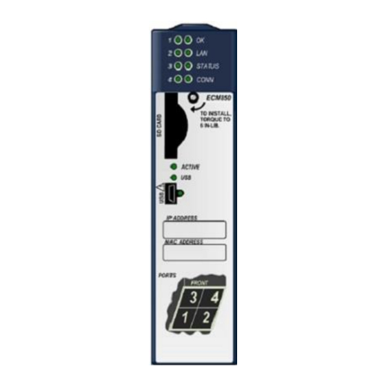
Quick Start Guide Chapter 1 GFK-2851A Sep 2019 1. User Features Figure 1.1: Module Overview Overview 1.1. IEC 61850 Port Module Status Activity Indicator LEDs: Indicator LEDs: OK, LAN, The PACSystems RX3i IEC STATUS STATUS, CONN 61850 Ethernet CONN ECM850 SD Card Slot Communication Module, TO INSTALL,... -
Page 6: Ethernet Ports
Quick Start Guide Chapter 1 GFK-2851A Sep 2019 Ethernet Ports 1.2. The ECM850 connects to one IEC 61850 network by means of one or more of its four external Ethernet ports. Two 8-conductor RJ- 45 shielded twisted pair 10/100/1000 Mbps copper interfaces and two Small Form-factor Pluggable (SFP) cages provide flexibility in media selection. - Page 7 Quick Start Guide Chapter 1 GFK-2851A Sep 2019 SFP Modules Each SFP cage on the bottom of an ECM850 is capable of accepting the SFP devices listed below. SFP devices can be removed and replaced during module operation. Modal Wave Medi Core Bandwidth...
-
Page 8: Micro Usb Port
100 (max) 1000 CAT5e BASE-T / CAT6 Emerson part number IC695SPF002 Emerson part number IC695SPC100 Micro USB Port 1.3. The ECM850 has a USB Micro-B socket for connection to a computer. It can be used to access the ECM850’s Command Line Interface function following the installation of special drivers. -
Page 9: Restart Pushbutton
Quick Start Guide Chapter 1 GFK-2851A Sep 2019 Restart Pushbutton 1.4. The Restart pushbutton can be used to manually restart the module without cycling power. The restart operation begins when the pushbutton is released. Light-Emitting Diode Indicators (LEDs) 1.5. OK —indicates whether the module is able to perform normal operations. - Page 10 Quick Start Guide Chapter 1 GFK-2851A Sep 2019 Fatal error. Flashes once between Blink pattern error codes blinked on the STATUS No network activity STATUS —indicates the condition of the ECM850 during normal operation. It is reset when the local log is cleared. For more information see the Command Line Interface clear log command.
- Page 11 Quick Start Guide Chapter 1 GFK-2851A Sep 2019 CONFIG —indicates whether the module has received its configuration from the RX3i CPU. Green, ON Configured Not configured Fatal error. Flashes once between Green, blink error codes blinked on the STATUS pattern ACTIVE —indicates the status of IEC 61850 connections.
- Page 12 Quick Start Guide Chapter 1 GFK-2851A Sep 2019 USB —indicates activity on the USB port. Green, USB port activity Blinking No USB port activity User Features...
- Page 13 Quick Start Guide Chapter 1 GFK-2851A Sep 2019 Port LEDs — The ECM850 has four Port Indicator LEDs, 1, 2, 3, and 4 that indicate link speed, link connection and link activity corresponding to the four possible external Ethernet ports. Blue, ON Link connected, 1000 Mbps Blue, blinking...
-
Page 14: Hardware Installation
As the consignee, it is your responsibility to register a claim with the carrier for damage incurred during shipment. Emerson Electric Company will fully cooperate with you, however, should such action be necessary. -
Page 15: Installation Location
This equates to a NEMA/UL Type 1 enclosure or an IP20 rating (IEC60529) providing at least a pollution degree 2 environment. For details about installing RX3i rack systems, refer to GFK-2314. If you need technical help, contact Technical Support weblink https://www.emerson.com/Industrial-Automation- Controls/support. Installation in Hazardous Areas 2.3. - Page 16 Quick Start Guide Chapter 2 GFK-2851A Sep 2019 • Suitable for use in Class I, Division 2, Groups A, B, C and D Hazardous Locations, or nonhazardous locations only. WARNING • EXPLOSION HAZARD - SUBSTITUTION OF COMPONENTS MAY IMPAIR SUITABILITY FOR CLASS I, DIVISION 2. •...
-
Page 17: Module Installation
Quick Start Guide Chapter 2 GFK-2851A Sep 2019 Module Installation 2.4. The ECM850 must be installed in the main (CPU) rack of an RX3i system, using a Universal Backplane such as IC695CHS007, CHS012 or CHS016. The ECM850 supports insertion/removal while power is applied to the system (hot swap). This module is compatible with RX3i... - Page 18 Quick Start Guide Chapter 2 GFK-2851A Sep 2019 Removing the Backplane Knockout The back of the ECM850 has an exposed heat sink and backplane connector. Before inserting the module into the backplane, remove the plastic knockout in the slot where the module will be placed(see figure).
- Page 19 Quick Start Guide Chapter 2 GFK-2851A Sep 2019 • Swing the module down until the module’s connector engages the backplane’s backplane connector. • Visually inspect the module to be sure it is properly seated. • Turn the heat sink screw on the front of the module several turns into the threaded hole in the backplate using a flat-tip screwdriver, but do not tighten.
-
Page 20: Ethernet Port Connections To Iec 61850 Lan
Quick Start Guide Chapter 2 GFK-2851A Sep 2019 Ethernet Port Connections to IEC 61850 2.5. Each port on an ECM850 operates independently through an embedded Ethernet switch, so devices that operate at different speeds and/or duplex modes can be attached to different ports. Each port automatically detects the attached cable and functions properly with either straight-through or crossover cables. - Page 21 Quick Start Guide Chapter 2 GFK-2851A Sep 2019 Direct The simplest scheme is the direct connection of IEDs to the ports of the ECM850. This limits the number of IEDs served by an ECM850 to four. Figure 2.2: Direct Connection of IEDs Hardware Installation...
- Page 22 Quick Start Guide Chapter 2 GFK-2851A Sep 2019 Linear Some IEDs are provided with at least two Ethernet ports and an internal Ethernet switch, allowing them to be connected in a daisy-chain as shown below. Figure 2.3: IEDs connected in a daisy chain Hardware Installation...
- Page 23 Quick Start Guide Chapter 2 GFK-2851A Sep 2019 Star (Switched) When more than a few IEDs must be networked, the preferred method of connecting the devices is by means of one or more network switches. The diagram below shows a single ECM850 port connected to one port of a switch, leaving the remainder of the switch’s ports available for connection to IEDs.
-
Page 24: Configuration
Description (CID) files for the devices in your system, available from the device manufacturers. • PACSystems RX3i IEC 61850 Ethernet Communication Module User Manual, GFK-2849, available from the Emerson support website, https://www.emerson.com/en-us/support will need to refer to this manual to fully configure and commission the ECM850. -
Page 25: Next Steps
Quick Start Guide Chapter 3 GFK-2851A Sep 2019 supply, and CPU in the Project tab of the Navigator, go online with the target, right-click on the target and select Online Commands, Show Status…, Details, to display the Device Information Details window. This queries the CPU and all modules present on all racks in the system, whether configured or not. - Page 26 Quick Start Guide Chapter 3 GFK-2851A Sep 2019 the Module Catalog, select the IC695ECM850 module. Double-clicking the slot with the IC695ECM850 displays a Settings grid where you can enter (among others) the module’s IEC 61850 network IP address, subnet mask, and Status Address.
- Page 27 Quick Start Guide Chapter 3 GFK-2851A Sep 2019 downloaded to the RX3i controller for validation and deployment. Status and Diagnastic Data...
-
Page 28: Status And Diagnostic Data
Quick Start Guide Chapter 4 GFK-2851A Sep 2019 4. Status and Diagnostic Data Module Status Data (32 bits) 4.1. Name Description 1 indicates the module is functioning properly. Module OK (LSB) 0 indicates the module is powering up or has failed Port1 Link Up 1 indicates the port is connected to another device and is operating... -
Page 29: Problems During Powerup And Reset
All Indicator LEDs off. Invalid bootstrap Module unresponsive. image No Indicator LEDs turn on Return the module and the module is to Emerson. unresponsive, or Invalid boot image The STATUS LED is solid green and is the only LED Fatal powerup... - Page 30 Quick Start Guide Chapter 4 GFK-2851A Sep 2019 Problem Indication Action failure Customer Service. Module powers up normally, Non-fatal Note the fault and but an entry is added to the initialization contact Customer Local Log table and the RX3i failure Service.
-
Page 31: Additional Information
PACSystems RX3i IEC 61850 Ethernet Communication Module Important Product Information, GFK-2850. User manuals, product updates and other information sources available Support website, https://www.emerson.com/Industrial-Automation- Controls/support. under Controllers and IO, RX3i Controllers. Information about IEC 61850 5.2. For detailed information about the IEC 61850 standard, contact... - Page 32 © 2019 Emerson. All rights reserved. Emerson Terms and Conditions of Sale are available upon request. The Emerson logo is a trademark and service mark of Emerson Electric Co. All other marks are the property of their respective owners.