
Related Manuals for Generac Power Systems MAGNUM MLT4250


Summary of Contents for Generac Power Systems MAGNUM MLT4250
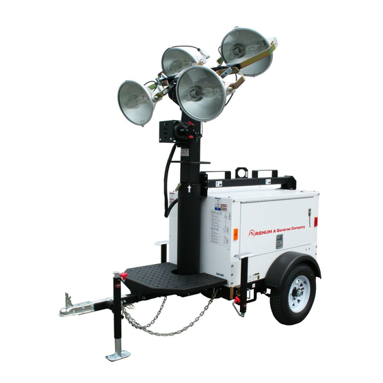
- Page 1 Owner’s Manual Light Tower MLT4250 www.discount-equipment.com SAVE THIS MANUAL FOR FUTURE REFERENCE...
- Page 2 Discount-Equipment.com is your online resource for commercial and industrial quality parts and equipment sales. Locations: Florida (West Palm Beach): 561-964-4949 Outside Florida TOLL FREE: 877-690-3101 Need parts? Check out our website at www.discount-equipment.com Can’t find what you need? Click on this link: http://www.discount-equipment.com/category/5443-parts/ and fill out the request form.
- Page 3 Use this page to record important information about your Light Tower Record the information found on your unit data label on this page. See unit serial number location (Unit Serial Unit Model Number Number Locations). The label plate is affixed to the inside partition, to the left of the control panel console.
-
Page 4: Table Of Contents
Table of Contents Section 1: Introduction and Safety MDC Operational Status ........17 MDC Alarm Management ........17 Introduction ............1 Read This Manual Thoroughly ........1 MDC List of Alarms ........... 18 How to Obtain Service ..........1 MDC History ............19 Safety Rules ............1 Adjusting the Backlighting ....... - Page 5 Winch Use, Operation and Maintenance ..34 Prior to Use ............... 34 Operation ..............34 Maintenance ............. 34 Optional Lower Radiator Hose Heater Use and Maintenance ............34 Trailer Wheel Bearings ........34 Jack Maintenance ..........35 Section 5:Troubleshooting General Troubleshooting ........37 Troubleshooting the Lights ......38 Section 6:Wiring Diagrams Mast Junction Box Wiring and Light Connections ............39...
-
Page 6: Section 1: Introduction And Safety
Introduction and Safety Section 1: Introduction and Safety Introduction Safety Rules Thank you for purchasing a Generac Mobile Products LLC The manufacturer cannot anticipate every possible product. This unit has been designed to provide high circumstance that might involve a hazard. The warnings in performance, efficient operation, and years of use when this manual, and on tags and decals affixed to the unit are, maintained properly. -
Page 7: General Hazards
Introduction and Safety General Hazards Explosion and Fire Hazards DANGER DANGER Asphyxiation. Running engines produce Explosion and Fire. Fuel and vapors are carbon monoxide, a colorless, odorless, extremely flammable and explosive. Add fuel poisonous gas. Carbon monoxide, if not in a well ventilated area. Keep fire and spark away. -
Page 8: Electrical Hazards
Introduction and Safety Electrical Hazards Battery Hazards DANGER DANGER Electrocution. In the event of electrical accident, Electrocution. Do not wear jewelry while immediately shut power OFF. Use non-conductive working on this equipment. Doing so will implements to free victim from live conductor. Apply result in death or serious injury. -
Page 9: Fuel Hazards
Introduction and Safety Fuel Hazards Operating Safety DANGER Positioning the Unit Explosion and fire.Fuel and vapors are extremely DANGER flammable and explosive. No leakage of fuel is High Voltage. Verify area above unit is clear permitted. Keep fire and spark away. Failure to do of overhead wires and obstructions. -
Page 10: Raising And Lowering The Mast
Introduction and Safety Service Safety Raising and Lowering the Mast WARNING This unit uses high voltage circuits capable of causing serious injury or death. Only a qualified and licensed Electrocution. Do not set up or operate electrician should troubleshoot or repair problems this unit if severe weather is expected. -
Page 11: Towing Safety
Introduction and Safety Towing Safety Reporting Trailer Safety Defects Towing a trailer requires care. Both the trailer and vehicle If you believe your trailer has a defect which could cause must be in good condition and securely fastened to each a crash or could cause injury or death, you should other to reduce the possibility of an accident. -
Page 12: Section 2: General Information
General Information Section 2: General Information Specifications DESCRIPTION UNITS MLT4250 Engine Make/Brand — Isuzu Model — 4LE1NYGV-03 / 4LE1NYGV-03E EPA Tier — Type Diesel, liquid cooled, 4-stroke Horsepower - prime hp (kW) 31.5 (23.5) Horsepower - standby hp (kW) 34.5 (25.7) Operating Speed 1800 Displacement... - Page 13 General Information Unit Dimensions 004647 Figure 2-1. Unit Dimensions 170 in 70 in 30 ft 68 in 140 in MLT4250 (4.32 m) (1.78 m) (9.14 m) (1.73 m) (3.56 m) Specifications are subject to change without notice. Owner’s Manual for MLT Light Tower...
-
Page 14: Unit Serial Number Locations
General Information Unit Serial Number Locations Refer to the illustration to locate the unit ID tag and Vehicle Identification Number (VIN) tag on the unit. Important information, such as the unit serial number, model number, VIN and tire loading information are found on these tags. -
Page 15: Component Locations
General Information Component Locations LEFT SIDE RIGHT SIDE 004497 Figure 2-3. Component Location Mast rotation knob Lower Forklift pockets Upper forklift pockets Central lifting point Battery Fuel fill Engine exhaust Control box Outriggers Emergency Stop Switch Radiator box Engine access Owner’s Manual for MLT Light Tower... -
Page 16: Main Control Panel
General Information Main Control Panel 004678 Figure 2-4. Control Panel (A) Receptacle Panel Main Circuit Breaker (100A) (G) Cable Access This breaker disconnects power to the receptacle panel. Allows for entry of load cables to the connection lugs with the lug box door closed. (B) Individual Circuit Breaker (H) Remote Start Terminal Block One breaker is supplied for each light. -
Page 17: Section 3:Operation
Operation Section 3: Operation Light Tower Setup DETAIL C DETAIL D DETAIL G DETAIL H 004659 Figure 3-1. Set Up Outriggers and Jacks 2. See Figure 3-1. Place the unit on firm ground that is relatively flat (less than 5° slope), and then block DANGER the wheels to keep it from moving (A).This will make it easier to level the unit. -
Page 18: Raising The Mast
Operation into place. Turn the jack handle clockwise to start leveling the trailer. 7. Rotate each jack handle clockwise to start leveling the trailer. Adjust all four jacks by rotating their handles clockwise until they are firmly in contact DETAIL A DETAIL C DETAIL E with the ground (G). -
Page 19: Magnum Digital Controller (Mdc) Features And Functions
Operation Magnum Digital Controller (MDC) Features and Functions 004679 Figure 3-3. Magnum Digital Controller (A) Control Power Switch and Fine Voltage Adjust- • Page Select: Pressing this button will select the ment Screw next display screen. • Control Power Switch: This toggle switch powers •... -
Page 20: Engine Monitoring
Operation NOTE: When loading the generator, it is important to Additional information may be viewed while the unit is in observe the amperage to determine the load balance on Manual or Auto mode. By pressing the Page Select each line of the generator. Minor load unbalances, button, the operator will select one of the following usually 10% or less, will not cause any particular screens: Running, Password, or History. -
Page 21: Mdc Fault Reset
Operation The most recent alarm or code is the first to be No. Engine State Description listed, with the time/date of the alarm or code at the bottom of the screen. The controller stores up to Prestart sequence in process, pre- Prestart codes. -
Page 22: Mdc List Of Alarms
Operation MDC List of Alarms Information on Events Protection Binary Output Description Specification Type Available Shutdown alarm configurable on the input of IG-IOM/IGS- AnInIOM Sd PTM. AnInIOM Wrn Warning alarm configurable on the input of IG-IOM/IGS-PTM. If the controller switches off during starting sequence due to Battery Flat (low bad battery condition, it doesn’t try to start again and acti- battery) -
Page 23: Mdc History
Operation Information on Events Protection Binary Output Description Specification Type Available The generator voltage is unbalanced more than the value of Vgen unbal Volt unbal setpoint. ECU alarm list is not empty. (Not available on MLG, MLT or Wrn ECU Alarm MTT units.) Warning alarm in case of lost connection to IGL-RA15 mod- Wrn RA15 fail... -
Page 24: Voltage Selector Switch
Operation 277/480V 3-PHASE L1-L2 = 480V L1-N = 277V 120/ 208V L2-L3 = 480V L2-N = 277V L3-L1 = 480V L3-N = 277V 277/ VOLTAGES AT RECEPTACLES 480V RECEPTACLE GFCI 139V GFCI w/Buck 120V Twist-locks 240V 139V Switch styles vary by model. = Not recommended for normal use 002810 120/208V 3-PHASE... -
Page 25: Prestart Checklist
Operation Prestart Checklist Before starting the unit, all items in the prestart check- list must be completed. This checklist applies to both manual and remote starting of the unit. WARNING Consult Manual. Read and understand manual completely before using product. Failure to completely understand manual and product could result in death or serious injury. - Page 26 Operation 004532 004534 Figure 3-16. Run Screen Figure 3-14. Engine Prestart 7. See Figure 3-17. The LCD window will then toggle 5. See Figure 3-15. The Starting screen will be from the Running screen to the generator screen displayed. The engine will crank and start running. and then to the engine screen.
-
Page 27: Starting The Unit-Auto/Remote
Operation 11. Check the unit for excessive noise or vibration and 5. Secure the unit by closing and locking all access any coolant, oil, or fuel leaks before applying any doors. loads. 6. The unit is now ready for remote starting. 12. -
Page 28: Auxiliary Outlets
Operation Wet Stacking down, they require a cool down period of approximately ten minutes before they can be switched on again. The unit is powered by a diesel engine. Diesel engines NOTE: The light tower uses four 1000W or 1050W are susceptible to wet stacking if lightly loaded. -
Page 29: Remote Start Terminal Block
Operation Make sure any problems that caused the main circuit breaker to trip are corrected before returning the switch to the ON (I) position. NOTE: The main circuit breaker interrupts power to the connection lugs only. The receptacle panel has power even if the main circuit breaker is in the OFF (O) position. -
Page 30: Auto Exercise Time
Operation Auto Exercise Time panel. This screw turns a rheostat that will provide an increase (+) or a decrease (-) in the generator output Units installed in a standby application should be voltage as displayed on the generator display screen on exercised regularly to maintain operating condition and to the MDC. -
Page 31: Lowering The Mast
Operation aligned and the metal stop tabs are touching. c. Tighten the mast rotation knob. NEUTRAL BONDED TO FRAME NULL-LEITER AM RAHMEN ANGESCHLOSSEN CONDUCTOR NEUTRO CONECTADO AL CHASIS CONDUCTEUR NEUTRE MIS A LA MASSE DU CHASSIS 3. Turn upper mast winch handle GENERATOR... -
Page 32: Towing The Unit
Operation NOTE: When installing the lights, verify the star washer 8. If driving over rough ground, remove the bulbs from is in place between the trunnion and T-handle before the light fixtures. tightening. 9. Check for proper inflation of the trailer tires. For maximum tire pressures, refer to Specifications. - Page 33 Operation sure the mast winch handles or any other obstructions are clear of the forklift tines before lifting. 004666 Figure 3-26. Lifting Point Owner’s Manual for MLT Light Tower...
-
Page 34: Section 4:Maintenance
Maintenance Section 4: Maintenance Emissions Information Activate (push in) the Emergency Stop Switch. Disconnect the negative (–) terminal on the battery. For warranty information, please refer to the diesel Attach a “Do Not Start” sign to the control panel. engine manual supplied with this unit. This will notify everyone that the unit is being serviced and will reduce the chance of someone Daily Walk-Around Inspection... -
Page 35: Basic Maintenance Schedule
Maintenance Basic Maintenance Schedule • Verify the wheel lugs are present and properly tightened. Refer to Towing Safety. Refer to the original equipment manufacturer’s operating • Check the coolant level daily by inspecting the manual for a complete list of maintenance requirements. level in coolant overflow jug located near the Failure to comply with the procedures as described in the radiator. -
Page 36: Resetting The "Time To Service" Reminder
Maintenance Table 4-1. Basic Maintenance Guide (Isuzu) 1000 Item Daily Hours Hours Hours Check Oil Level Check Coolant Level Check Fuel Level Drain Fuel Filter Check Tire Pressure Check All Electrical Connections Clean Battery ... -
Page 37: Winch Use, Operation And Maintenance
Maintenance Press ENTER to save the current run time hour setting. Move the Control Power switch to the OFF (O) position. Winch Use, Operation and Main- tenance Prior to Use • Inspect rope or cable and replace if damaged. • Check mounting hardware for proper tightness and re-torque if necessary. -
Page 38: Jack Maintenance
Maintenance Use only a high quality grease made specifically for lubrication of wheel bearings. Wipe any excess grease from the hub with a clean cloth and replace the rubber plug when finished. The minimum recommended lubrication is every 12 months or 12,000 miles (19,312 km);... -
Page 39: Section 5:Troubleshooting
Troubleshooting Section 5: Troubleshooting General Troubleshooting Some of the more common problems are listed in the table below. This information is intended to be a check or verification that simple causes can be located and fixed. It does not cover all types of problems. Refer to the OEM engine operator’s manual for additional troubleshooting information. -
Page 40: Troubleshooting The Lights
Troubleshooting Troubleshooting the Lights WARNING IMPORTANT NOTE: Only a qualified electrician should troubleshoot or repair electrical problems Burn hazard. Lamps become extremely hot occurring in this equipment. while in use. Allow 10–15 minutes for cooling before handling or lowering mast. Touching a hot lens or fixture can cause severe burns. -
Page 41: Section 6:Wiring Diagrams
Wiring Diagrams Section 6: Wiring Diagrams Mast Junction Box Wiring and Light Connections 00768 Owner’s Manual for MLT Light Tower... -
Page 42: Ac Wiring Diagram
Wiring Diagrams AC Wiring Diagram 90380_B_06.23.14 Owner’s Manual for MLT Light Tower... -
Page 43: Ac Wiring Diagram-Receptacle Panel
Wiring Diagrams AC Wiring Diagram—Receptacle Panel TO MAIN BREAKER TO NEUTRAL TO GROUND (2x5-20R, 1xTT-30, 1xL14-30R, 2x14-50) 90317_ORG_07.06.11 Owner’s Manual for MLT Light Tower... -
Page 44: Ac Wiring Diagram-Receptacle Panel Options (1 Of 2)
Wiring Diagrams AC Wiring Diagram—Receptacle Panel Options (1 of 2) 30 AMP 30 AMP 50 AMP 50 AMP CIRCUIT CIRCUIT CIRCUIT CIRCUIT BREAKER BREAKER BREAKER BREAKER 20 AMP 20 AMP CIRCUIT CIRCUIT BREAKER BREAKER 240 VOLT 240 VOLT 240 VOLT 240 VOLT 30 AMP 30 AMP... -
Page 45: Ac Wiring Diagram-Receptacle Panel Options (2 Of 2)
Wiring Diagrams AC Wiring Diagram—Receptacle Panel Options (2 of 2) 30 AMP 30 AMP 30 AMP 50 AMP CIRCUIT CIRCUIT CIRCUIT CIRCUIT BREAKER BREAKER BREAKER BREAKER 20 AMP 20 AMP CIRCUIT CIRCUIT BREAKER BREAKER 240 VOLT 240 VOLT 240 VOLT 240 VOLT 30 AMP 30 AMP... -
Page 46: Dc Wiring Diagram
Wiring Diagrams DC Wiring Diagram Owner’s Manual for MLT Light Tower... -
Page 47: Dc Wiring Diagram-Optional Equipment
Wiring Diagrams DC Wiring Diagram—Optional Equipment 90323_K_06.04.14 Owner’s Manual for MLT Light Tower... -
Page 48: Trailer Lights Wiring
Wiring Diagrams Trailer Lights Wiring SPADE SPADE 90341_B_12.20.13 Owner’s Manual for MLT Light Tower... - Page 49 www.discount-equipment.com Part No. 13134 Rev. D 3/7/17 ©2017 Generac Mobile Products All rights reserved. Specifications are subject to change without notice. No reproduction allowed in any form without prior written consent from Generac Mobile Products.