
Related Manuals for Generac Power Systems Magnum MLT4150MV


Summary of Contents for Generac Power Systems Magnum MLT4150MV
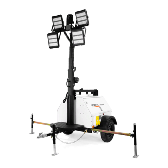
- Page 1 Owner’s Manual Light Tower MLT4150MV • MLT4200IV• MLT4200IVCAN www.discount-equipment.com SAVE THIS MANUAL FOR FUTURE REFERENCE...
- Page 2 Discount-Equipment.com is your online resource for commercial and industrial quality parts and equipment sales. Locations: Florida (West Palm Beach): 561-964-4949 Outside Florida TOLL FREE: 877-690-3101 Need parts? Check out our website at www.discount-equipment.com Can’t find what you need? Click on this link: http://www.discount-equipment.com/category/5443-parts/ and fill out the request form.
- Page 3 Use this page to record important information about your Light Tower Record the information found on your unit data label on this page. See unit serial number location (Unit Serial Unit Model Number Number Locations). The label plate is affixed to the inside partition, to the left of the control panel console.
-
Page 4: Table Of Contents
Table of Contents Section 1: Introduction and Safety Automatic Shutdown ........16 Light Operation ..........16 Introduction ............1 Read This Manual Thoroughly ........1 Auxiliary Outlets ..........17 How to Obtain Service ..........1 Voltage Regulation ..........17 Safety Rules ............1 Wet Stacking ............17 General Hazards ..........2 Engine Derating .......... - Page 5 AC Wiring Diagram—Receptacle Panel Options (2 of 2) ..........33 DC Wiring Diagram ..........34 DC Wiring Diagram—Electric Winch ....35 DC Wiring Diagrams for Optional Equipment .36 Trailer Lights Wiring ..........37 Section 7:Service Log Owner’s Manual for MLT Light Tower...
-
Page 6: Section 1: Introduction And Safety
Introduction and Safety Section 1: Introduction and Safety Introduction Safety Rules Thank you for purchasing a Generac Mobile Products LLC The manufacturer cannot anticipate every possible product. This unit has been designed to provide high circumstance that might involve a hazard. The warnings in performance, efficient operation, and years of use when this manual, and on tags and decals affixed to the unit are, maintained properly. -
Page 7: General Hazards
Introduction and Safety General Hazards Explosion and Fire Hazards DANGER DANGER Asphyxiation. Running engines produce Explosion and Fire. Fuel and vapors are carbon monoxide, a colorless, odorless, extremely flammable and explosive. Add fuel poisonous gas. Carbon monoxide, if not in a well ventilated area. Keep fire and spark away. -
Page 8: Electrical Hazards
Introduction and Safety Electrical Hazards Battery Hazards DANGER DANGER Electrocution. In the event of electrical accident, Electrocution. Do not wear jewelry while immediately shut power OFF. Use non-conductive working on this equipment. Doing so will implements to free victim from live conductor. Apply result in death or serious injury. -
Page 9: Fuel Hazards
Introduction and Safety Fuel Hazards Operating Safety DANGER Positioning the Unit Explosion and fire.Fuel and vapors are extremely DANGER flammable and explosive. No leakage of fuel is permitted. Keep fire and spark away. Failure to do High Voltage. Verify area above unit is clear of overhead wires and obstructions. -
Page 10: Raising And Lowering The Mast
Introduction and Safety Service Safety Raising and Lowering the Mast WARNING This unit uses high voltage circuits capable of causing serious injury or death. Only a qualified and licensed Burn hazard. Lamps become extremely hot electrician should troubleshoot or repair problems while in use. -
Page 11: Towing Safety
Introduction and Safety Towing Safety Reporting Trailer Safety Defects Towing a trailer requires care. Both the trailer and vehicle If you believe your trailer has a defect which could cause must be in good condition and securely fastened to each a crash or could cause injury or death, you should other to reduce the possibility of an accident. -
Page 12: Section 2: General Information
General Information Section 2: General Information Specifications DESCRIPTION UNITS MLT4150MV MLT4200IV Engine Make/Brand — Mitsubishi Isuzu Model — S4L2-W41ML 4LE1NYGV-03/4LE1NYG-03E EPA Tier — Type — Diesel, liquid cooled, 4-stroke Horsepower - prime hp (kW) 23.5 (17.5) 31.5 (23.5) Horsepower - standby hp (kW) 24.7 (18.4) 34.5 (25.7) - Page 13 General Information DESCRIPTION UNITS MLT4200IVCAN Engine Make/Brand — Isuzu Model — 4LE1NYGV-03G1 EPA Tier — Type — Diesel, liquid cooled, 4-stroke Horsepower - prime hp (kW) 31.5 (23.5) Horsepower - standby hp (kW) 34.5 (25.7) Operating Speed 1800 Displacement 134.25 (2.20) Cylinders Fuel Consumption—100% Prime gph (Lph)
-
Page 14: Unit Dimensions
General Information Unit Dimensions 004621 Figure 2-1. Unit Dimensions MLT4150MV 115 in 107 in 25 ft 68 in 140 in MLT4200IV (2.92 m) (2.71 m) (7.6 m) (1.73 m) (3.56 m) MLT4200IVCAN Specifications are subject to change without notice. Owner’s Manual for MLT Light Tower... -
Page 15: Unit Serial Number Locations
General Information Unit Serial Number Locations Refer to the illustration to locate the unit ID tag and Vehicle Identification Number (VIN) tag on the unit. Important information, such as the unit serial number, model number, VIN and tire loading information are found on these tags. -
Page 16: Component Locations
General Information Component Locations LEFT SIDE RIGHT SIDE 004505 Figure 2-3. Component Locations Engine Exhaust Control Box Outriggers Mast Switch Central Lifting Point Engine Access Forklift Pockets Mast Rotation Knob Radiator Access Battery Fuel Fill — — Owner’s Manual for MLT Light Tower... -
Page 17: Control Panel
General Information Control Panel BALLAST INDICATOR LIGHTS MAIN BREAKER 240V TURN MAIN BREAKER LIGHT SWITCHES GLOW PLUG INDICATOR GLOW PLUG START BREAKER NEUTRAL BONDED TO FRAME 004625 Figure 2-4. Control Panel Control Panel Features and Functions (G) Engine Hour Meter Keeps track of engine hours for service. -
Page 18: Section 3:Operation
Operation Section 3: Operation Light Tower Setup DETAIL C DETAIL D DETAIL G DETAIL H 004627 Figure 3-1. Set Up Outriggers and Jacks 2. See Figure 3-1. Place the unit on firm ground that is relatively flat (less than 5° slope), and then block DANGER the wheels to keep it from moving (A).This will make it easier to level the unit. -
Page 19: Prestart Checklist
Operation place. Turn the jack handle clockwise to start Verify the emergency stop switch is pulled out. leveling the trailer. 7. Rotate each jack handle clockwise to start leveling Raising the Mast the trailer. Adjust all four jacks by rotating their 1. -
Page 20: Emergency Stop Switch
Operation 2. See Figure 3-2. Check both sets of mast cables for excessive wear or damage. verify the cables are properly centered in each pulley (A). Check the electrical cord for damage. 3. Press and hold the winch control toggle switch (B) upward to telescope the mast to the desired height. -
Page 21: Automatic Shutdown
Operation 4. See Figure 3-7. Release the key, it will move to the RUN position. GLOW GLOW PLUG PLUG START START 003792 Figure 3-5. Activate Glow Plug 003794 Figure 3-7. Release Key 3. See Figure 3-6. Turn the key to the right START position and hold it until the engine cranks and 5. -
Page 22: Auxiliary Outlets
Operation Each receptacle has an individual circuit breaker which is located behind the receptacle panel. The breakers are labeled with the corresponding amperage for the receptacle they protect. BALLAST INDICATOR LIGHTS MAIN With all of the lights off, the full generator output may be BREAKER 240V used with the receptacles. -
Page 23: Engine Derating
Operation Engine Derating The winch and lights should be facing toward the back of the unit. All units are subject to derating for altitude and c. Tighten the mast rotation knob. temperature. Derating reduces the available power for 3. Press and hold the winch control toggle switch operating tools and accessories connected to the outlets. -
Page 24: Towing The Unit
Operation 2. Remove the two flange head screws (B) securing tighten the lugs, in the order shown, to the the winch motor assembly to the winch. Retain the following specifications: screws for reassembly. 3. Carefully remove the motor assembly (C), verifying the two pieces do not separate. - Page 25 Operation 004506 Figure 3-13. Lifting Point Owner’s Manual for MLT Light Tower...
-
Page 26: Section 4:Maintenance Emissions Information
Maintenance Section 4: Maintenance Emissions Information Disconnect the negative (–) terminal on the battery. Attach a “Do Not Start” sign to the control panel. For warranty information, please refer to the diesel This will notify everyone that the unit is being engine manual supplied with this unit. -
Page 27: Basic Maintenance Schedule
Maintenance Basic Maintenance Schedule • Verify the safety pins for the mast lock rod and mast lock bar are present and secured with a Refer to the original equipment manufacturer’s operating chain. Check that the spring located in the mast manual for a complete list of maintenance requirements. - Page 28 Maintenance Table 4-1. Basic Maintenance Guide (Mitsubishi) 1000 ITEM DAILY Hours Hours Hours Hours Hours Check oil level Check coolant level Check fuel level Check tire pressure Check all electrical connections Inspect radiator fins for debris, clean as required ...
-
Page 29: Winch Use, Operation And Maintenance
Maintenance Table 4-2. Basic Maintenance Guide (Isuzu) 1000 Item Daily Hours Hours Hours Check Oil Level Check Coolant Level Check Fuel Level Drain Fuel Filter Check Tire Pressure Check All Electrical Connections Clean Battery ... -
Page 30: Optional Lower Radiator Hose Heater Use And Maintenance
Maintenance Overheating the mechanical brake may result in permanent damage to, or failure of, the brake. Replace any damaged brake components before resuming use of the winch. Table 4-3. Winch Preventative Maintenance Schedule After First Maintenance Activity Before Each Use Semi-Annually Operation Check Fasteners... - Page 31 Maintenance 002306 Figure 4-2. Jack Maintenance Owner’s Manual for MLT Light Tower...
-
Page 32: Section 5:Troubleshooting
Troubleshooting Section 5: Troubleshooting General Troubleshooting Some of the more common problems are listed in the table below. This information is intended to be a check or verification that simple causes can be located and fixed. It does not cover all types of problems. Refer to the OEM engine operator’s manual for additional troubleshooting information. -
Page 33: Troubleshooting The Lights
Troubleshooting Troubleshooting the Lights WARNING IMPORTANT NOTE: Only a qualified electrician should troubleshoot or repair electrical problems Burn hazard. Lamps become extremely hot occurring in this equipment. while in use. Allow 10–15 minutes for cooling before handling or lowering mast. Touching a hot lens or fixture can cause severe burns. -
Page 34: Section 6:Wiring Diagrams
Wiring Diagrams Section 6: Wiring Diagrams Mast Junction Box Wiring and Light Connections 00768 Owner’s Manual for MLT Light Tower... -
Page 35: Ac Wiring Diagram
Wiring Diagrams AC Wiring Diagram 90454_C_11.25.14 Owner’s Manual for MLT Light Tower... -
Page 36: Ac Wiring Diagram-Receptacle Panel
Wiring Diagrams AC Wiring Diagram—Receptacle Panel TO MAIN BREAKER TO NEUTRAL TO GROUND (2x5-20R, 1xTT-30, 1xL14-30R, 2x14-50) 90317_ORG_07.06.11 Owner’s Manual for MLT Light Tower... -
Page 37: Ac Wiring Diagram-Receptacle Panel Options (1 Of 2)
Wiring Diagrams AC Wiring Diagram—Receptacle Panel Options (1 of 2) 30 AMP 30 AMP 50 AMP 50 AMP CIRCUIT CIRCUIT CIRCUIT CIRCUIT BREAKER BREAKER BREAKER BREAKER 20 AMP 20 AMP CIRCUIT CIRCUIT BREAKER BREAKER 240 VOLT 240 VOLT 240 VOLT 240 VOLT 30 AMP 30 AMP... -
Page 38: Ac Wiring Diagram-Receptacle Panel Options (2 Of 2)
Wiring Diagrams AC Wiring Diagram—Receptacle Panel Options (2 of 2) 30 AMP 30 AMP 30 AMP 50 AMP CIRCUIT CIRCUIT CIRCUIT CIRCUIT BREAKER BREAKER BREAKER BREAKER 20 AMP 20 AMP CIRCUIT CIRCUIT BREAKER BREAKER 240 VOLT 240 VOLT 240 VOLT 240 VOLT 30 AMP 30 AMP... -
Page 39: Dc Wiring Diagram
Wiring Diagrams DC Wiring Diagram 90322_B_03.07.14 Owner’s Manual for MLT Light Tower... -
Page 40: Dc Wiring Diagram-Electric Winch
Wiring Diagrams DC Wiring Diagram—Electric Winch 90443_H_06.10.14 Owner’s Manual for MLT Light Tower... -
Page 41: Dc Wiring Diagrams For Optional Equipment
Wiring Diagrams DC Wiring Diagrams for Optional Equipment 90323_K_06.04.14 Owner’s Manual for MLT Light Tower... -
Page 42: Trailer Lights Wiring
Wiring Diagrams Trailer Lights Wiring SPADE SPADE 90341_B_12.20.13 Owner’s Manual for MLT Light Tower... - Page 43 Discount-Equipment.com is your online resource for commercial and industrial quality parts and equipment sales. Locations: Florida (West Palm Beach): 561-964-4949 Outside Florida TOLL FREE: 877-690-3101 Need parts? Check out our website at www.discount-equipment.com Can’t find what you need? Click on this link: http://www.discount-equipment.com/category/5443-parts/ and fill out the request form.
- Page 44 www.discount-equipment.com Part No. 33330 Rev. C 3/9/17 ©2017 Generac Mobile Products All rights reserved. Specifications are subject to change without notice. No reproduction allowed in any form without prior written consent from Generac Mobile Products.