Table of Contents
Troubleshooting

Related Manuals for Miller HYDRACOOL 1 V.115 50/60HZ


Summary of Contents for Miller HYDRACOOL 1 V.115 50/60HZ
- Page 1 OM-254203E 2016−09 Processes TIG (GTAW) Welding MIG (GMAW) Welding Description Hydracool 1 Hydracool 2 OWNER’S MANUAL For product information, Owner’s Manual translations, and more, visit www.MillerWelds.com...
- Page 2 From Miller to You Thank you and congratulations on choosing Miller. Now you can get the job done and get it done right. We know you don’t have time to do it any other way. That’s why when Niels Miller first started building arc welders in 1929, he made sure his products offered long-lasting value and superior quality.
-
Page 3: Table Of Contents
TABLE OF CONTENTS SECTION 1 − SAFETY PRECAUTIONS - READ BEFORE USING ....... . . 1-1. - Page 4 Council Directive(s) and Standard(s). Product/Apparatus Identification: Product Stock Number HYDRACOOL 1 V.115 50/60HZ 028042103 HYDRACOOL 1 V.230 50/60HZ 028042104 HYDRACOOL 2 V.115 50/60HZ 028042105 HYDRACOOL 2 V.230 50/60HZ...
-
Page 5: Section 1 − Safety Precautions - Read Before Using
SECTION 1 − SAFETY PRECAUTIONS - READ BEFORE USING coolers 2016-08 Protect yourself and others from injury — read, follow, and save these important safety precautions and operating instructions. 1-1. Symbol Usage DANGER! − Indicates a hazardous situation which, if Indicates special instructions. -
Page 6: California Proposition 65 Warnings
MOVING PARTS can injure. STEAM AND HOT COOLANT can burn. D Keep away from moving parts such as fans. Hose may rupture if coolant overheats. D Keep all doors, panels, covers, and guards D Visually inspect condition of hoses before each closed and securely in place. -
Page 7: Section 2 − Definitions
SECTION 2 − DEFINITIONS 2-1. Additional Safety Symbols And Definitions Some symbols are found only on CE products. Warning! Watch Out! There are possible hazards as shown by the symbols. Safe1 2012−05 Do not discard product (where applicable) with general waste. Reuse or recycle Waste Electrical and Electronic Equipment (WEEE) by disposing at a designated collection facility. -
Page 8: Miscellaneous Symbols And Definitions
Plugged filter or hoses can cause overheating to the power source and torch. Safe50 2012−05 100 h. Std. Every 100 hours, check and clean filter and check condition of hoses. Safe51 2012−05 2-2. Miscellaneous Symbols And Definitions Water (Coolant) Amperage Hertz Output Alternating... -
Page 9: Section 3 − Specifications
SECTION 3 − SPECIFICATIONS 3-1. Serial Number And Rating Label Location The serial number and rating information for this product is located on the back panel. Use rating label to determine input power requirements and/or rated output. For future reference, write serial number in space provided on cover of this manual. 3-2. -
Page 10: Section 4 − Installation
B. Information On Electromagnetic Compatibility (EMC) This Class A equipment is not intended for use in residential locations where the electrical power is provided by the public low− voltage supply system. There can be potential difficulties in ensuring electromagnetic compatibility in those locations, due to con- ducted as well as radiated disturbances. -
Page 11: Section 5 − Operation
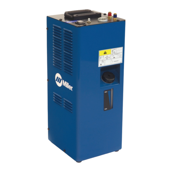
SECTION 5 − OPERATION 5-1. Control Panel Hydracool 1 Quick Connect; Water In Quick Connect; Water Out Flow Indicator Circuit Breaker (CB1) Power On/Off switch Tank Filler Neck Coolant level Indicator 956142899_2-A 5-2. Control Panel Hydracool 2 Flow Indicator Power On/Off switch Circuit Breaker CB1 Tank Filler Neck Coolant Level... -
Page 12: Section 6 − Maintenance & Troubleshooting
SECTION 6 − MAINTENANCE & TROUBLESHOOTING 6-1. Routine Maintenance Disconnect power before maintaining. n = Check Z = Change ~ = Clean l = Replace Reference * To be done by Factory Authorized Service Agent Every NOTICE − Clean coolant filter. Severe condi- tions may require more frequent cleaning (con- Months tinuous use, high/low temperatures, dirty envi-... -
Page 13: Troubleshooting
6-3. Troubleshooting Trouble Remedy Be sure input power cord is plugged in to energized receptacle. Coolant system does not work. Check circuit breakers on cooler and welding power source, and reset if necessary. Motor overheated. Unit starts running when motor has cooled. Have Factory Authorized Service Agent check Power switch, capacitor, and motor. -
Page 14: Section 7 − Electrical Diagram
SECTION 7 − ELECTRICAL DIAGRAM 956142901_B OM-254203 Page 10... -
Page 15: Section 8 − Parts List
SECTION 8 − PARTS LIST Hardware is common and not available unless listed. 956142899_3-A Figure 8-1. Main Assembly, Hydracool 1 OM-254203 Page 11... - Page 16 Item Dia. Part Mkgs. Description Figure 8-1. Main Assembly, Hydracool 1 ... . 213072 Fan, Muffin 115V 60HZ 3400 RPM 6.378 Mtg Holes ....
- Page 17 Hardware is common and not available unless listed. Figure 8-2. Main Assembly, Hydracool 2 956142900_3-A OM-254203 Page 13...
- Page 18 Item Dia. Part Mkgs. Description Figure 8-2. Main Assembly, Hydracool 2 ....207290 Label, Advisory Service ......... . .
- Page 19 Effective January 1, 2016 (Equipment with a serial number preface of MG or newer) This limited warranty supersedes all previous Miller warranties and is exclusive with no other guarantees or warranties expressed or implied. LIMITED WARRANTY − Subject to the terms and conditions 90 Days —...
- Page 20 File a claim for loss or damage during Phone: 39 (0) 2982901 Fax: 39 (0) 298290-203 shipment. email: miller@itw−welding.it For assistance in filing or settling claims, contact your distributor and/or equipment manufacturer’s Transportation Department. © ORIGINAL INSTRUCTIONS − PRINTED IN USA 2016 Miller Electric Mfg. Co. 2016−01...