
Related Manuals for Miller SUITCASE 12RC CE


Summary of Contents for Miller SUITCASE 12RC CE
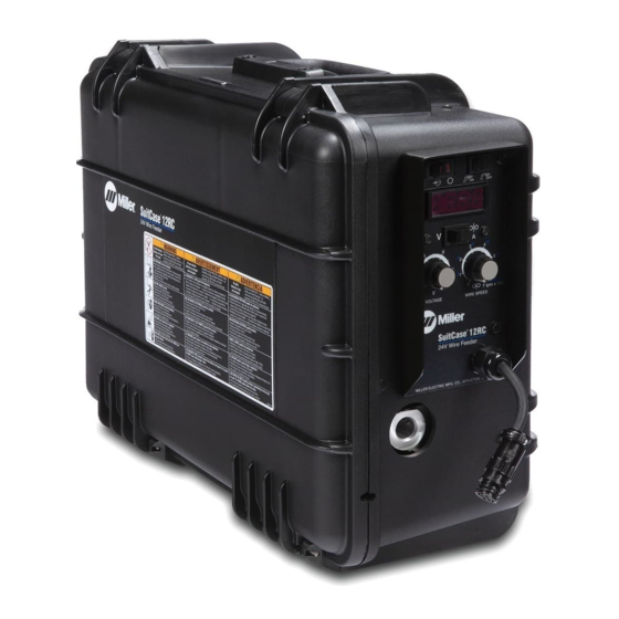
- Page 1 OM-1500-15 210 177Y 2009−07 Processes MIG (GMAW) Welding Flux Cored (FCAW) Welding Description Wire Feeder SuitCase 12RC ™ CE And Non-CE Models File: MIG (GMAW) Visit our website at www.MillerWelds.com...
- Page 2 We know you don’t have time to do it any other way. That’s why when Niels Miller first started building arc welders in 1929, he made sure his products offered long-lasting value and superior quality.
-
Page 3: Table Of Contents
TABLE OF CONTENTS SECTION 1 − SAFETY PRECAUTIONS - READ BEFORE USING ........1-1. -
Page 4: Declaration Of Conformity
DECLARATION OF CONFORMITY for European Community (CE marked) products. MILLER Electric Mfg. Co., 1635 Spencer Street, Appleton, WI 54914 U.S.A. declares that the product(s) identified in this declaration conform to the essential requirements and provisions of the stated Council Directive(s) and Standard(s). -
Page 5: Section 1 − Safety Precautions - Read Before Using
SECTION 1 − SAFETY PRECAUTIONS - READ BEFORE USING som _2009−07 Protect yourself and others from injury — read and follow these precautions. 1-1. Symbol Usage DANGER! − Indicates a hazardous situation which, if Indicates special instructions. not avoided, will result in death or serious injury. The possible hazards are shown in the adjoining symbols or explained in the text. - Page 6 D Remove stick electrode from holder or cut off welding wire at FUMES AND GASES can be hazardous. contact tip when not in use. D Wear oil-free protective garments such as leather gloves, heavy Welding produces fumes and gases. Breathing shirt, cuffless trousers, high shoes, and a cap.
-
Page 7: Additional Symbols For Installation, Operation, And Maintenance
1-3. Additional Symbols For Installation, Operation, And Maintenance FIRE OR EXPLOSION hazard. MOVING PARTS can injure. D Do not install or place unit on, over, or near D Keep away from moving parts such as fans. combustible surfaces. D Keep all doors, panels, covers, and guards D Do not install unit near flammables. -
Page 8: California Proposition 65 Warnings
1-4. California Proposition 65 Warnings For Gasoline Engines: Welding or cutting equipment produces fumes or gases which contain chemicals known to the State of California to Engine exhaust contains chemicals known to the State of cause birth defects and, in some cases, cancer. (California California to cause cancer, birth defects, or other reproduc- Health &... -
Page 9: Section 2 − Consignes De Sécurité − Lire Avant Utilisation
SECTION 2 − CONSIGNES DE SÉCURITÉ − LIRE AVANT UTILISATION fre_som_2009−07 Se protéger et protéger les autres contre le risque de blessure — lire et respecter ces consignes. 2-1. Symboles utilisés DANGER! − Indique une situation dangereuse qui si on Indique des instructions spécifiques. - Page 10 D Porter des vêtements confectionnés avec des matières résistan- Il reste une TENSION DC NON NÉGLIGEABLE dans tes et ignifuges (cuir, coton lourd ou laine) et des bottes de les sources de soudage onduleur UNE FOIS protection. l’alimentation coupée. LE SOUDAGE peut provoquer un D Arrêter les convertisseurs, débrancher le courant électrique et incendie ou une explosion.
-
Page 11: Dangers Supplémentaires En Relation Avec L'installation, Le Fonctionnement Et La Maintenance
ACCUMULATIONS LES BOUTEILLES peuvent exploser risquent de provoquer des blessures si elles sont endommagées. ou même la mort. Des bouteilles de gaz protecteur contiennent du gaz D Fermer l’alimentation du gaz protecteur en cas sous haute pression. Si une bouteille est endom- magée, elle peut exploser. -
Page 12: Proposition Californienne 65 Avertissements
Les PIÈCES MOBILES peuvent RAYONNEMENT HAUTE causer des blessures. FRÉQUENCE (H.F.) risque provoquer des interférences. D Ne pas s’approcher des organes mobiles. D Ne pas s’approcher des points de coincement D Le rayonnement haute fréquence (H.F.) peut tels que des rouleaux de commande. provoquer des interférences avec les équi- pements de radio−navigation et de com- munication, les services de sécurité... -
Page 13: Principales Normes De Sécurité
2-5. Principales normes de sécurité Safety in Welding, Cutting, and Allied Processes, ANSI Standard Z49.1, 25 West 43rd Street, New York, NY 10036 (téléphone : 212-642-4900, de Global Engineering Documents (téléphone : 1-877-413-5184, site site Internet : www.ansi.org). Internet : www.global.ihs.com). Standard for Fire Prevention During Welding, Cutting, and Other Hot Safe Practices for the Preparation of Containers and Piping for Welding Work, NFPA Standard 51B, de National Fire Protection Association,... - Page 14 OM-1500−15 Page 10...
-
Page 15: Section 3 − Definitions
SECTION 3 − DEFINITIONS 3-1. Warning Label Definitions Warning! Watch Out! There are possible hazards as shown by the symbols. Drive rolls can injure fingers Welding wire and drive parts are at welding voltage during operation − keep hands and metal objects clear. -
Page 16: Serial Number And Rating Label Location
3-2. Serial Number And Rating Label Location The serial number and rating information for this product is located inside the case. Use rating label to determine input power requirements and/or rated output. For future reference, write serial number in space provided on back cover of this manual. 3-3. -
Page 17: Symbols And Definitions
3-4. Symbols And Definitions Some symbols are found only on CE products. Output Input Amperes Volts Degree Of Protec- Duty Cycle Wire Feed Percent tion Cold Jog (Inch) To- Input Purge By Gas Fast wards Workpiece Constant Current Circuit Breaker Constant Voltage Slow Rated Welding... -
Page 18: Gun Recommendation Table
4-3. Gun Recommendation Table Process GMAW − Hard or Cored Wires Bernard Q300 or Q400 FCAW − Self-Shielding Wires FC-1260 Dura-Flux 4-4. Equipment Connection Diagram Turn Off wire feeder and welding power source. Stop engine on welding generator. Use only with CV DC Power Sources. -
Page 19: Installing And Aligning Wire Guide And Drive Rolls
4-5. Installing And Aligning Wire Guide And Drive Rolls Installing Wire Guide And Drive Rolls: Drive Securing Roll Nut Drive Roll Carrier Turn nut one click until lobes of nut line up with lobes of drive roll carrier. Drive Roll Slide drive roll onto drive roll carrier. -
Page 20: Connecting Welding Gun
4-6. Connecting Welding Gun Turn Off wire feeder and welding power source. Stop engine on welding generator. Gun Securing Knob Gun Block Gun Power Pin Loosen knob, insert gun end into block. Position power pin as close as possible to drive rolls without touching. -
Page 21: Connecting Weld Cable
4-8. Connecting Weld Cable User-Suppled Weld Cable Follow wire manufacturer’s recom- mendations for weld cable polarity. User-Suppled Male Connector User-Suppled Female Connector From Wire Feeder Push female connector over male connector, and turn 1/4 turn clock- wise. 804 211-A 4-9. Weld Cable Sizes* NOTICE −... -
Page 22: Installing And Threading Welding Wire
4-10. Installing And Threading Welding Wire Installing Wire And Adjusting Hub Tension: Hold wire tightly Retaining Nut to keep it from Hub Tension Adjustment unraveling. Screw Remove retaining ring, and install spool so hub pin fits spool hole. Re- install retaining nut. Adjust tension knob so only a slight force is needed to turn spool. -
Page 23: Section 5 − Operation
SECTION 5 − OPERATION 5-1. Controls Power Control Switch Trigger Hold Switch (Optional) Depress the upper part of the switch (turns trigger hold On) to weld without holding gun trigger throughout the weld cycle. To start weld, press and release gun trigger. -
Page 24: Setting Digital Meter Board Pc4 Dip Switches
5-2. Setting Digital Meter Board PC4 DIP Switches Front Meter Panel S1 DIP Switch S2 DIP Switch If the DIP switches are set to a Meter Hold (ON) position, the meter value will hold 5 seconds after gun is trig- gered. -
Page 25: Gun Consumables Information
5-3. Gun Consumables Information 235 264-A Notes OM-1500-15 Page 21... -
Page 26: Section 6 − Maintenance & Troubleshooting
SECTION 6 − MAINTENANCE & TROUBLESHOOTING 6-1. Routine Maintenance Disconnect power Maintain more often before maintaining. during severe conditions. 3 Months Replace Damaged Or Replace Damaged Unreadable Gas Hose Labels Repair Or Replace Cracked Cables And Cords 6 Months Clean Blow Out Or Drive Vacuum Inside... -
Page 27: Troubleshooting
6-3. Troubleshooting Trouble Remedy Wire does not feed, unit completely inop- Turn Power switch On. erative. Check 14−pin plug PLG2 connections. Check input power. Wire does not feed. Check circuit breaker CB1. (see Section 6-2). Check gun trigger connection at wire feeder. Check gun trigger leads and trigger switch. See gun Owner’s Manual. -
Page 28: Section 7 − Electrical Diagrams
SECTION 7 − ELECTRICAL DIAGRAMS 223 794-C Figure 7-1. Circuit Diagram For Wire Feeder OM-1500-15 Page 24... - Page 29 Notes MATERIAL THICKNESS REFERENCE CHART 24 Gauge (.025 in) 22 Gauge (.031 in) 20 Gauge (.037 in) 18 Gauge (.050 in) 16 Gauge (.063 in) 14 Gauge (.078 in) 1/8 in (.125 in) 3/16 in (.188 in) 1/4 in (.25 in) 5/16 in (.313 in) 3/8 in (.375 in) 1/2 in (.5 in)
-
Page 30: Section 8 − Parts List
SECTION 8 − PARTS LIST Hardware is common and not available unless listed. Figure 8-1. Complete Assembly 804 214-G OM-1500-15 Page 26... - Page 31 Item Dia. Part Description Mkgs. Quantity Figure 8-1. Complete Assembly ..220 195 Motor, Right Angle 24VDC 145 RPM 37.5 Ratio W/Plug ....
- Page 32 Item Dia. Part Description Mkgs. Quantity Figure 8-1. Complete Assembly (Continued) ... . . 222 181 Grommet, Scr No 8/10 Panel Hole .281 Sq .031 High ....
- Page 33 Item Dia. Part Description Mkgs. Quantity Figure 8-1. Complete Assembly (Continued) ..RC8, RC21 131 059 Housing Plug+Pins, (Service Kit) ........
- Page 34 Table 8-1. Drive Roll And Wire Guide Kits Base selection of drive rolls upon the following recommended usages: 1. V-Grooved rolls for hard wire. 2. U-Grooved rolls for soft and soft shelled cored wires. 3. U-Cogged rolls for extremely soft shelled wires (usually hard surfacing types). 4.
- Page 35 Effective January 1, 2009 (Equipment with a serial number preface of LK or newer) This limited warranty supersedes all previous Miller warranties and is exclusive with no other Warranty Questions? guarantees or warranties expressed or implied. LIMITED WARRANTY − Subject to the terms and conditions...
-
Page 36: Options And Accessories
Contact the Delivering Carrier to: File a claim for loss or damage during shipment. For assistance in filing or settling claims, contact your distributor and/or equipment manufacturer’s Transportation Department. © ORIGINAL INSTRUCTIONS − PRINTED IN USA 2009 Miller Electric Mfg. Co. 2009−01...