Table of Contents

Related Manuals for Miller Hydracool 1 CE


Summary of Contents for Miller Hydracool 1 CE
- Page 1 OM-254203K 2021-01 Processes TIG (GTAW) Welding MIG (GMAW) Welding Description Recirculating Coolant System Hydracool 1 OWNER’S MANUAL For product information, Owner’s Manual translations, and more, visit www.MillerWelds.com...
- Page 2 We know you don’t have time to do it any other way. That’s why when Niels Miller first started building arc welders in 1929, he made sure his products offered long-lasting value and superior quality.
-
Page 3: Table Of Contents
TABLE OF CONTENTS SECTION 1 – SAFETY PRECAUTIONS – READ BEFORE USING..............1 Symbol Usage . -
Page 5: Section 1 - Safety Precautions - Read Before Using
SECTION 1 – SAFETY PRECAUTIONS – READ BEFORE USING Protect yourself and others from injury—read, follow, and save these important safety precautions and operating instructions. 1-1. Symbol Usage DANGER! – Indicates a hazardous situation which, if not avoided, will result in death or serious injury. The possible hazards are shown in the adjoining symbols or explained in the text. -
Page 6: California Proposition 65 Warnings
� Read and understand the Safety Data Sheets (SDSs) and the � If ANY fluid is injected into the skin or body seek medical help manufacturer’s instructions for adhesives, coatings, cleaners, con- immediately. sumables, coolants, degreasers, fluxes, and metals. MOVING PARTS can injure. STEAM AND HOT COOLANT can burn. -
Page 7: Section 2 - Definitions
Safe15 2012 Safe97 201 1-1. Additional Safety Symbols And Definitions Wear dry insulating gloves. Do not touch electrode with bare hand. Do not wear wet or damaged gloves. Engine fuel plus flames or sparks can cause fire. SECTION 2 – DEFINITIONS Do not weld on drums or any closed containers. -
Page 8: Miscellaneous Symbols And Definitions
Remove unit from shipping crate. Remove Owner’s Manual from unit. Follow instructions to install muffler. Safe46 2012 05 Every 100 hours, check and clean filter and check condition of hoses. Every 100 hours, check and clean filter and check condition of hoses. Safe51 2012 05 2-2. -
Page 9: Section 3 - Specifications
SECTION 3 – SPECIFICATIONS 3-1. Serial Number And Rating Label Location The serial number and rating information is located on the left side of the unit. Use rating label to determine input power requirements and/or rated output. For future reference, write serial number in space provided on back cover of this manual. 3-2. -
Page 10: Section 4 - Installation
1-1. Selecting A Location Do not move or operate SECTION 4 – INSTALLATION unit where it could tip. 4-1. Selecting A Location Do not move or operate unit where it could tip. � Position unit so air can circulate. Position unit so air can circulate. 500 mm 500 mm 500 mm... -
Page 11: Section 5 - Operation
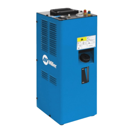
SECTION 5 – OPERATION 1-1. Control Panel Hydracool 1 Quick Connect; Water In 5-1. Control Panel Hydracool 1 Quick Connect; Water Out Flow Indicator Circuit Breaker (CB1) Power On/Off switch Tank Filler Neck Coolant level Indicator 1 Quick Connect: Water In 2 Quick Connect: Water Out 3 Flow Indicator 4 Circuit Breaker (CB1) -
Page 12: Section 6 - Maintenance
Every Months Months 805497-A 805497-A ◇ Change coolant (If using Miller coolant) OM-270536 Page 65 6-2. Coolant Maintenance Disconnect cooler plug from welding power source receptacle before maintaining. Dispose of used coolant according to national, state, and local codes. Do not pour down drain. -
Page 13: Troubleshooting
6-3. Troubleshooting Trouble Remedy Coolant system does not work. Be sure input power cord is plugged in to energized receptacle. Check circuit breakers on cooler and welding power source, and reset if necessary. Motor overheated. Unit starts running when unit has cooled. Have Factory Authorized Service Agent check power switch, capacitor, and motor. -
Page 14: Section 7 - Electrical Diagram
SECTION 7 – ELECTRICAL DIAGRAM 956142901_B OM-254203 Page 10... -
Page 15: Section 8 - Parts List
SECTION 8 – PARTS LIST 956142899_3-B Figure 8-1. Main Assembly, Hydracool 1 Figure 8-1. Main Assembly, Hydracool 1 OM-254203 Page 11... - Page 16 Main Assembly, Hydracool 1 Item No. Dia. Mkgs. Part No. Description Quantity 213072 Fan, Muffin 115V 60HZ 3400 RPM 6.378 Mtg Holes 235504 Fan Assy, Radiator Cooling 230 V +116117082 Fan Support 056082099 Radiator Assy 956142629 Label, Warning Moving Parts 207290 Label, Advisory Service 956142621...
- Page 17 Notes Visit www.youtube.com/ MillerWelders informational videos.
- Page 18 Notes...
-
Page 19: Warranty
Effective January 1, 2021 (Equipment with a serial number preface of NB or newer) This limited warranty supersedes all previous Miller warranties and is exclusive with no other guarantees or warranties expressed or implied. LIMITED WARRANTY − Subject to the terms and conditions Running Gear/Trailers below, Miller Electric Mfg. - Page 20 File a claim for loss or damage during Fax: +31 (0) 186 640 880 shipment. For assistance in filing or settling claims, contact your distributor and/or equipment manufacturer’s Transportation Department. © ORIGINAL INSTRUCTIONS − PRINTED IN USA 2020 Miller Electric Mfg. LLC 2020−01...