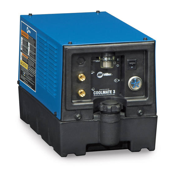
Summary of Contents for Miller Flowmax
- Page 1 OM-248 626C 2012−04 Processes TIG (GTAW) Welding MIG (GMAW) Welding Description Flowmax CE And Non-CE File: TIG (GTAW)
-
Page 3: Table Of Contents
TABLE OF CONTENTS SECTION 1 − SAFETY PRECAUTIONS - READ BEFORE USING ....... . . 1-1. - Page 4 DECLARATION OF CONFORMITY for European Community (CE marked) products. MILLER Electric Mfg. Co., 1635 Spencer Street, Appleton, WI 54914 U.S.A. declares that the product(s) identified in this declaration conform to the essential requirements and provisions of the stated Council Directive(s) and Standard(s).
-
Page 5: Section 1 − Safety Precautions - Read Before Using
SECTION 1 − SAFETY PRECAUTIONS - READ BEFORE USING coolers 2011−10 Protect yourself and others from injury — read, follow, and save these important safety precautions and operating instructions. 1-1. Symbol Usage DANGER! − Indicates a hazardous situation which, if Indicates special instructions. -
Page 6: California Proposition 65 Warnings
1-4. California Proposition 65 Warnings Welding or cutting equipment produces fumes or gases This product contains chemicals, including lead, known to which contain chemicals known to the State of California to the state of California to cause cancer, birth defects, or other cause birth defects and, in some cases, cancer. -
Page 7: Section 2 − Consignes De Sécurité − Lire Avant Utilisation
SECTION 2 − CONSIGNES DE SÉCURITÉ − LIRE AVANT UTILISATION Cooler 2011−03fre Pour écarter les risques de blessure pour vous−même et pour autrui — lire, appliquer et ranger en lieu sûr ces consignes relatives aux précautions de sécurité et au mode opératoire. 2-1. -
Page 8: Proposition Californienne 65 Avertissements
Les PIÈCES MOBILES peuvent LIRE LES INSTRUCTIONS. causer des blessures. D Lire et appliquer les instructions sur les D S’abstenir de toucher des organes mobiles tels étiquettes et le Mode d’emploi avant l’instal- que des ventilateurs. lation, l’utilisation ou l’entretien de l’appareil. Lire les informations de sécurité... -
Page 9: Section 3 − Definitions
SECTION 3 − DEFINITIONS 3-1. WEEE Label (For Products Sold Within The EU) Do not discard this product (where applicable) with general waste. Reuse or recycle Waste Electrical and Electronic Equipment (WEEE) by disposing at a designated collec- tion facility. Contact your local recycling office or your local distributor for further information. -
Page 10: Section 4 − Specifications
SECTION 4 − SPECIFICATIONS 4-1. Important Information Regarding CE Products (Sold Within The EU) This equipment shall not be used by the general public as the EMF limits for the general public might be exceeded during welding. This equipment is built in accordance with EN 60974−1 and is intended to be used only in an occupational environment (where the general public access is prohibited or regulated in such a way as to be similar to occupational use) by an expert or an instructed person. -
Page 11: Section 5 − Installation
SECTION 5 − INSTALLATION 5-1. GTAW Connections Tools Needed: 5/8 in. 801 190-D 115 Or 230 Volt AC Grounded Re- Coolant In Hose Do not move or operate unit where ceptacle (Depending On Model) it could tip. Fittings have 5/8-18 left-hand threads. Connect hoses with proper fittings as An individual circuit capable of carrying 15 shown. -
Page 12: Gmaw Connections
5-2. GMAW Connections Tools Needed: 5/8 in. 801 191-D 115 Or 230 Volt AC Grounded Re- Coolant Out Hose Do not move or operate unit where ceptacle (Depending On Model) it could tip. Coolant In Hose An individual circuit capable of carrying 15 230 volt AC coolers only: Replace Fittings have 5/8-18 left-hand threads. -
Page 13: Section 6 − Maintenance & Troubleshooting
SECTION 6 − MAINTENANCE & TROUBLESHOOTING 6-1. Routine Maintenance Disconnect power before maintaining. n = Check Z = Change ~ = Clean = Repair l = Replace * To be done by Factory Authorized Service Agent Every ~ Blow out heat exchanger fins. ~Coolant Filter, durning heavy Months nCheck coolant level. -
Page 14: Section 7 − Parts List
Input power 135 796-D 187 733-A Figure 6-2. Circuit Diagram For 230 Volt Model Figure 6-1. Circuit Diagram For 115 Volt Model SECTION 7 − PARTS LIST *included with item 24 805 487-B Figure 7-1. Complete Assembly OM-248 626 Page 10... - Page 15 Mkgs. Description Quantity Flowmax-115 Figure 7-1. Complete Assembly Flowmax-230 CE ..+166 562 ..WRAPPER ........... . .
- Page 16 Notes TM-216 869 Page 12 Dynasty 350/700, Maxstar 350/700...
- Page 17 Notes...
- Page 18 Notes TM-216 869 Page 14 Dynasty 350/700, Maxstar 350/700...
- Page 19 Warranty Effective January 1, 2012 (Equipment with a serial number preface of MC or newer) This limited warranty supersedes all previous manufacturers 90 Days — Parts warranties and is exclusive with no other guarantees or Accessory (Kits) warranties expressed or implied. Canvas Covers Induction Heating Coils and Blankets, Cables, and LIMITED WARRANTY −...
- Page 20 Owner’s Record Please complete and retain with your personal records. Model Name Serial/Style Number Purchase Date (Date which equipment was delivered to original customer.) Distributor Address City State Resources Available Always provide Model Name and Serial/Style Number. Contact your Distributor for: Welding Supplies and Consumables Options and Accessories Personal Safety Equipment...


