
Related Manuals for Miller Hydracool 1


Summary of Contents for Miller Hydracool 1
- Page 1 OM-254203H 2020-02 Processes TIG (GTAW) Welding MIG (GMAW) Welding Description Hydracool 1 OWNER’S MANUAL For product information, Owner’s Manual translations, and more, visit www.MillerWelds.com...
- Page 2 From Miller to You Thank you and congratulations on choosing Miller. Now you can get the job done and get it done right. We know you don’t have time to do it any other way. That’s why when Niels Miller first started building arc welders in 1929, he made sure his products offered long-lasting value and superior quality.
-
Page 3: Table Of Contents
..............5-1. Control Panel Hydracool 1 . -
Page 5: Section 1 − Safety Precautions - Read Before Using
SECTION 1 − SAFETY PRECAUTIONS - READ BEFORE USING coolers 2020-02 Protect yourself and others from injury — read, follow, and save these important safety precautions and operating instructions. 1-1. Symbol Usage DANGER! − Indicates a hazardous situation which, if Indicates special instructions. -
Page 6: California Proposition 65 Warnings
READ INSTRUCTIONS. HIGH PRESSURE FLUIDS can injure or kill. D Read and follow all labels and the Owner’s D Coolant can be under high pressure. Manual carefully before installing, operating, or D Release pressure before working on cooler. servicing unit. Read the safety information at the beginning of the manual and in each D If ANY fluid is injected into the skin or body seek medical help section. -
Page 7: Section 2 − Definitions
SECTION 2 − DEFINITIONS 2-1. Additional Safety Symbols And Definitions Some symbols are found only on CE products. Warning! Watch Out! There are possible hazards as shown by the symbols. Safe1 2012−05 Do not discard product (where applicable) with general waste. Reuse or recycle Waste Electrical and Electronic Equipment (WEEE) by disposing at a designated collection facility. -
Page 8: Miscellaneous Symbols And Definitions
Plugged filter or hoses can cause overheating to the power source and torch. Safe50 2012−05 100 h. Std. Every 100 hours, check and clean filter and check condition of hoses. Safe51 2012−05 2-2. Miscellaneous Symbols And Definitions Water (Coolant) Amperage Hertz Output Alternating... -
Page 9: Section 3 − Specifications
3-4. Environmental Specifications A. IP Rating IP Rating Hydracool 1 IP21 This equipment is designed for indoor use and is not intended to be used or stored outside. IP21 2014−06 B. Information On Electromagnetic Compatibility (EMC) This Class A equipment is not intended for use in residential locations where the electrical power is provided by the public low−... -
Page 10: Section 4 − Installation
SECTION 4 − INSTALLATION 4-1. Selecting A Location Do not move or operate unit where it could tip. Position unit so air can circulate. 500 mm 500 mm 500 mm 956142899_1-A, 956142900_1-A OM-254203 Page 6... -
Page 11: Section 5 − Operation
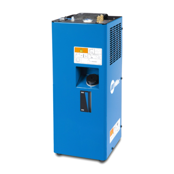
SECTION 5 − OPERATION 5-1. Control Panel Hydracool 1 Quick Connect; Water In Quick Connect; Water Out Flow Indicator Circuit Breaker (CB1) Power On/Off switch Tank Filler Neck Coolant level Indicator 956142899_2-A SECTION 6 − MAINTENANCE & TROUBLESHOOTING 6-1. Routine Maintenance Disconnect power before maintaining. -
Page 12: Coolant Maintenance
6-2. Coolant Maintenance Disconnect cooler plug from welding power source receptacle before maintaining. Dispose of used coolant according to national, state, and local codes. Do not pour down drain. Changing Coolant Drain coolant by tipping unit forward. Fill with clean water and run for 10 minutes. Drain and refill. NOTICE −... -
Page 13: Section 7 − Electrical Diagram
SECTION 7 − ELECTRICAL DIAGRAM 956142901_B OM-254203 Page 9... - Page 14 SECTION 8 − PARTS LIST Hardware is common and not available unless listed. 956142899_3-B Figure 8-1. Main Assembly, Hydracool 1 OM-254203 Page 10...
- Page 15 Item Dia. Part Mkgs. Description Figure 8-1. Main Assembly, Hydracool 1 ... . 213072 Fan, Muffin 115V 60HZ 3400 RPM 6.378 Mtg Holes ....
- Page 16 Notes...
- Page 17 Notes...
- Page 18 Notes...
- Page 19 Effective January 1, 2020 (Equipment with a serial number preface of NA or newer) This limited warranty supersedes all previous Miller warranties and is exclusive with no other guarantees or warranties expressed or implied. LIMITED WARRANTY − Subject to the terms and conditions Positioners and Controllers below, Miller Electric Mfg.
- Page 20 File a claim for loss or damage during Fax: +31 (0) 186 640 880 shipment. For assistance in filing or settling claims, contact your distributor and/or equipment manufacturer’s Transportation Department. © ORIGINAL INSTRUCTIONS − PRINTED IN USA 2020 Miller Electric Mfg. LLC 2020−01...