Table of Contents
Troubleshooting

Related Manuals for Miller Maxstar 152


Summary of Contents for Miller Maxstar 152
- Page 1 OM-172 200B August 1999 Processes TIG (GTAW) Welding Stick (SMAW) Welding With Optional Equipment: Pulsed TIG (GTAW-P) Welding Description Arc Welding Power Source Maxstar 152 Visit our website at www.MillerWelds.com...
-
Page 2: Table Of Contents
TABLE OF CONTENTS SECTION 1 – SAFETY PRECAUTIONS - READ BEFORE USING ......1-1. - Page 3 Declaration of Conformity For European Community (CE) Products Miller Electric Mfg. Co. Manufacturer’s Name: 1635 W. Spencer Street Manufacturer’s Address: Appleton, WI 54914 USA Maxstar 152 Declares that the product: conforms to the following Directives and Standards: Directives Electromagnetic compatibility Directives: 89/336/EEC, 92/31/EEC...
-
Page 4: Section 1 - Safety Precautions - Read Before Using
SECTION 1 – SAFETY PRECAUTIONS - READ BEFORE USING som _nd_4/98 1-1. Symbol Usage Means Warning! Watch Out! There are possible hazards with this procedure! The possible hazards are shown in the adjoining symbols. This group of symbols means Warning! Watch Out! possible Y Marks a special safety message. - Page 5 ARC RAYS can burn eyes and skin. BUILDUP OF GAS can injure or kill. D Shut off shielding gas supply when not in use. Arc rays from the welding process produce intense D Always ventilate confined spaces or use visible and invisible (ultraviolet and infrared) rays that can burn eyes and skin.
-
Page 6: Additional Symbols For Installation, Operation, And Maintenance
1-3. Additional Symbols For Installation, Operation, And Maintenance FIRE OR EXPLOSION hazard. MOVING PARTS can cause injury. D Do not install or place unit on, over, or near D Keep away from moving parts such as fans. combustible surfaces. D Keep all doors, panels, covers, and guards D Do not install unit near flammables. -
Page 7: Emf Information
1-5. EMF Information Considerations About Welding And The Effects Of Low Frequency 1. Keep cables close together by twisting or taping them. Electric And Magnetic Fields 2. Arrange cables to one side and away from the operator. Welding current, as it flows through welding cables, will cause electro- magnetic fields. -
Page 8: Section 1 - Consignes De Securite - Lire Avant Utilisation
SECTION 1 – CONSIGNES DE SECURITE – LIRE AVANT UTILISATION som _nd_fre 4/98 1-1. Signification des symboles Signifie Mise en garde ! Soyez vigilant ! Cette procédure présente des risques de danger ! Ceux-ci sont identifiés par des symboles adjacents aux directives. Ce groupe de symboles signifie Mise en garde ! Soyez vigilant ! Il y a des Y Identifie un message de sécurité... - Page 9 LES RAYONS DE L’ARC peuvent pro- LES ACCUMULATIONS DE GAZ ris- voquer des brûlures dans les yeux et quent de provoquer des blessures ou sur la peau. même la mort. Le rayonnement de l’arc du procédé de soudage D Fermer l’alimentation du gaz protecteur en cas de génère des rayons visibles et invisibles intenses non utilisation.
-
Page 10: Dangers Supplémentaires En Relation Avec L'installation, Le Fonctionnement Et La Maintenance
1-3. Dangers supplémentaires en relation avec l’installation, le fonctionnement et la maintenance Risque D’INCENDIE OU DES ORGANES MOBILES peuvent D’EXPLOSION. provoquer des blessures. D Ne pas placer l’appareil sur, au-dessus ou à proxi- D Rester à l’écart des organes mobiles comme le mité... -
Page 11: Principales Normes De Sécurité
1-4. Principales normes de sécurité Safety in Welding and Cutting, norme ANSI Z49.1, de l’American Wel- Safe Handling of Compressed Gases in Cylinders, CGA Pamphlet P-1, ding Society, 550 N.W. Lejeune Rd, Miami FL 33126 de la Compressed Gas Association, 1235 Jefferson Davis Highway, Suite 501, Arlington, VA 22202. -
Page 12: Section 2 - Definitions
SECTION 2 – DEFINITIONS 2-1. Manufacturer’s Warning Label Definitions For CE Products Warning! Watch Out! There are possible hazards as shown by the symbols. Electric shock from welding electrode or wiring can kill. 1.1 Wear dry insulating gloves. Do not touch electrode with bare hand. - Page 13 Warning! Watch Out! There are possible hazards as shown by the symbols. Electric shock from wiring can kill. Disconnect input plug or power before working on machine. Hazardous voltage remains on input capacitors after power is turned off. Do not touch fully charged capacitors.
-
Page 14: Rating Label For Ce Products
2-2. Rating Label For CE Products Ref. ST-179 381-A 2-3. Symbols And Definitions NOTE Some symbols are found only on CE products. Shielded Metal Arc Amperage Panel Voltage Welding (SMAW) Output Lift-Arc Remote High Temperature Negative Voltage Input Direct Current Gas Tungsten Arc Protective Earth Positive... -
Page 15: Section 3 - Installation
SECTION 3 – INSTALLATION NOTE Unless otherwise noted, the CE model is shown throughout this manual. 3-1. Specifications Amperes Input at Rated Load Output, 50 Hz, Single-Phase 100% Duty Rated Maximum Cycle Welding Amperage Open-Circuit Overall 230 V Output Voltage DC Weight Range Rating... -
Page 16: Volt-Ampere Curves
3-3. Volt-Ampere Curves The volt-ampere curves show the minimum and maximum voltage and amperage output capabilities of the welding power source. Curves of other settings fall between the curves shown. ssb1.1 10/91 – SB-151 604 3-4. Installing Power Cord (CE Models Only) Remove base plate. -
Page 17: Selecting A Location And Connecting Input Power
3-5. Selecting A Location And Connecting Input Power Plate Label Rating Label Use rating label to determine input power needs. User-Supplied Plug Install plug according to manufac- 10 in (254 mm) of tures instructions. space for airflow Receptacle (User-Supplied, May Vary According To Location) Install receptacle according to manufactures instructions. -
Page 18: Weld Output Receptacles And Selecting Cable Sizes
3-6. Weld Output Receptacles And Selecting Cable Sizes Y ARC WELDING can cause Electromagnetic Interference. To reduce possible interference, keep weld cables as short as possible, close together, and down low, such as on the floor. Locate welding operation 100 meters from any sensitive electronic equipment. Be sure this welding machine is installed and grounded according to this manual. -
Page 19: Section 4 - Operation
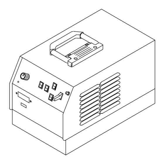
SECTION 4 – OPERATION 4-1. Front Panel Controls Ref. ST-179 381-A Amperage Adjustment Control For weld output, place switch in On position. Off position for other than Lift-Arc TIG welding. Amperage Control Switch For remote control, make connections to For front panel control, place switch in Panel Power On/Off Switch Remote 14 receptacle, and place switch in position. -
Page 20: Lift-Arc Tig Procedure
4-2. Lift-Arc TIG Procedure With Lift-Arc Switch in the On posi- tion, start an arc as follows: TIG Electrode Workpiece Touch tungsten electrode to work- piece at weld start point, hold electrode to workpiece for 1-2 seconds, and slowly lift electrode. An arc will form when electrode is lifted. -
Page 21: Replacing Power Cord In Non-Ce Models
5-2. Replacing Power Cord In Non-CE Models Y Turn Off welding power source, disconnect input power, and check voltage on input capacitor according to Section before proceeding. Have only qualified persons carry out this procedure. Remove wrapper. Input Terminal Block Input Conductors Grounding Conductor Disconnect input conductors and... -
Page 22: Troubleshooting
5-4. Troubleshooting Trouble Remedy No weld output; unit completely Place line disconnect switch in On position (see Section 3-5). inoperative. Check and replace line fuse(s), if necessary, or reset circuit breaker (see Section 3-5). Check for proper input power connections (see Section 3-5). No weld output;... -
Page 23: Section 6 - Electrical Diagrams
SECTION 6 – ELECTRICAL DIAGRAMS SC-169 778 Figure 6-1. Circuit Diagram For Non-CE Models OM-172 200 Page 20... - Page 24 SC-181 506 Figure 6-2. Circuit Diagram For CE Models OM-172 200 Page 21...
-
Page 25: Section 7 - Parts List
SECTION 7 – PARTS LIST Hardware is common and not available unless listed. Items 55 and 56 are used on in- ternational model only. ST-801 587-A Figure 7-1. Main Assembly (CE Model Illustrated) OM-172 200 Page 22... - Page 26 Item Dia. Part Mkgs. Description Quantity Figure 7-1. Main Assembly ....134 327 LABEL, warning general precautionary (international) ....
- Page 27 Item Dia. Part Quantity Mkgs. Description Figure 7-1. Main Assembly (Continued) ....157 958 LIGHT, ind white lens 28V ........
- Page 28 Item Dia. Part Mkgs. Description Quantity Figure 7-2. Module, Power & Diode (Fig 7-1 Item 25 & 26) ....093 085 CAPACITOR, polye MF .0047uf 1000V ......
- Page 29 Notes OM-172 200 Page 26...
- Page 30 Notes OM-172 200 Page 27...
- Page 31 Notes OM-172 200 Page 28...
- Page 32 Distributor Address City State For Service Call 1-800-4-A-Miller or see our website at www.MillerWelds.com to locate a DISTRIBUTOR or SERVICE AGENCY near you. Always provide Model Name and Serial/Style Number. Contact your Distributor for: Welding Supplies and Consumables Options and Accessories...