Table of Contents
Advertisement
Quick Links
NXG-183x Series Keypad User Manual
EN
1
(2)
(5)
(8)
EN: User Manual
Description
The NXG-183x is an interface for users of the xGen family of
security systems.
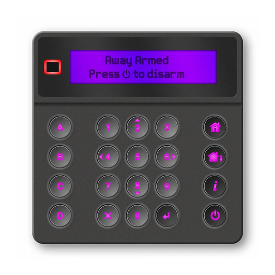
Figure 1: NXG-183x Keypad layout
(1) Graphical screen
(2) Status LED
(3) Arm Stay button
(4) Arm Away button
(5) Functional buttons A, B, C, D
(6) System Info (i) button
Entering a PIN
You will need to enter a valid PIN to access various features
and system information.
After a period of inactivity, a screensaver will appear and the
keypad will go into power save mode. Press any button to
wake it up. A screen will appear requesting to enter your PIN.
A valid PIN is required to unlock the screen and access the
system.
Enter Your Code, then
****
Enter a valid user code followed by Enter. User PINs can be
between 4 and 8 digits in length. The default master user PIN
is 1234.
© 2020 UTC Fire & Security Americas Corporation, Inc.
(1)
(3)
(4)
(6)
(7)
(9)
(10)
(11)
(7) Disarm button
(8) Cancel button
(9) Navigation buttons: Up (2),
Down (8), Left (4), Right (6)
(10) Enter button ()
(11) Selection button (5)
If the PIN is invalid for the feature you are trying to access, the
Access Denied warning message will be shown.
Permissions are assigned to users and keypads to determine
what features a user can access and at what times. If you are
unable to access a feature, contact your installation company
or building manager.
System status
The xGen security system displays system status messages
on the screen (Figure 1, item 1). For example, the main screen
below shows the Fault system status category.
Fault
Press i for Info
To get more details about the system fault, press the System
Info (i) button.
Other system status categories are Alarm, Bypassed, Not
Ready, Ready, Armed, etc.
Note that more than one system status category can be shown
at the same time. The screen will scroll through each category
automatically. You can manually scroll through them as well by
pressing Up (2) or Down (8) button.
Note:
In the alarm condition, only the alarm status category
and messages are shown, until the alarm is acknowledged by
pressing the Disarm (Item 7) button and entering a valid PIN.
Other status categories are not shown in this state.
If prompted, press the System Info (i) button (Figure 1, item 6)
to display the list of messages on the current status category.
Zone in tamper
2 – Main Warehouse Ent_i
To scroll through multiple alarms in the category, press Up (2)
or Down (8) button.
Names of partitions or zones may not fit within the display. In
this case, scroll left or right by pressing the System Info (i)
button.
See also "System Status Messages" on page 6.
Status LED
The status LED (Figure 1, item 2) may show one the following
system statuses (starting from the highest priority):
•
Flashing red: Alarm
•
Blue: Fault, Programming Mode On, System Not Ready,
System is ready to force arm
1 / 8
P/N 466-5559 • REV A • ISS 04MAY20
Advertisement
Table of Contents

Related Manuals for Interlogix NXG-183 Series


Summary of Contents for Interlogix NXG-183 Series
- Page 1 NXG-183x Series Keypad User Manual If the PIN is invalid for the feature you are trying to access, the Access Denied warning message will be shown. Permissions are assigned to users and keypads to determine what features a user can access and at what times. If you are unable to access a feature, contact your installation company or building manager.
- Page 2 • Yellow: Bypass, Armed in Stay mode Instant Stay Mode provides a higher level of security and • Green: Ready to Arm requires the system to be disarmed (from inside or remotely) • Red: Armed in Away mode before entering the protected partition. Attempts to enter the partition will trigger an instant alarm with no entry delay.
- Page 3 before arming will be allowed. See next chapter or contact Each button can be assigned to one of the following your installation company for assistance. programmable functions: • • Wireless sensor supervision faults Quick Chime toggle (assigned to button C by default) •...
-
Page 4: Navigating The Main Menu
Navigating the Main Menu - PIN - User type (Standard / Duress / Arm only / Custom / To enter the user or programming menu, depending on the Master) user privileges, press Enter, enter your PIN, then press Enter - Language again. - Page 5 - Panel Details Program User PINs Each user has a unique PIN code that allows him access to Performing Additional Functions various features of the system. Only users with master level authority are able to add, modify and remove users. To Bypass and Unbypass Zones Enter a valid PIN code to unlock the screensaver.
-
Page 6: Set Keypad Options
- Communicator Test: Test that the system is able to send for automatic time update or set the clock manually from a alarm messages. The result appears within a few keypad. seconds. • AC power fail: The security system has lost its electrical - Zone Walk Test: Verify if each sensor is able to send power. -
Page 7: Regulatory Information
Current consumption: Nominal NXG-1830, NXG-1831: TBD Contact information NXG-1832, NXG-1833: TBD Minimal (all lights off) NXG-1830, NXG-1831: TBD firesecurityproducts.com or www.interlogix.com NXG-1832, NXG-1833: 65 mA max. at 12 VDC P/N 466-5559 • REV A • ISS 04MAY20 7 / 8... - Page 8 P/N 466-5559 • REV A • ISS 04MAY20 8 / 8...