Advertisement
Quick Links
Advertisement

Related Manuals for neighbor Haven 4-Piece Sectional Teak Arm


Summary of Contents for neighbor Haven 4-Piece Sectional Teak Arm
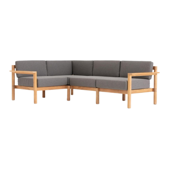
- Page 1 Haven 4-Piece Sectional Teak Arm Assembly Guide...
- Page 2 Components Assembly Instructions Contact Frame Boxes Left Module - Teak Arm Frame (1) Right Module - Teak Arm Frame (1) Armless Module Frame (1) Corner Module Frame (1) Cushion Boxes Cushions - Armless/Teak Arm (3) Cushions - Corner Module (1)
- Page 3 Components Assembly Instructions Contact Parts Module Back Support Left Module - Teak Arm Frame Box Right Module - Teak Arm Frame Box Armless Module Frame Box Module Roped Back Left Module - Teak Arm Frame Box Right Module - Teak Arm Frame Box Armless Module Frame Box Module Bases Corner Module Base...
- Page 4 Components Assembly Instructions Contact Cushions Hardware 30mm Hex Bolt All Frame Boxes Module Back Cushion Armless/Teak Arm Cushion Box 40mm Hex Bolt Left Module - Teak Arm Frame Box Right Module - Teak Arm Frame Box Module Base Cushion Armless/Teak Arm Cushion Box 60mm Hex Bolt Corner Module Frame Box Long Corner Module Back Cushion...
- Page 5 Components Assembly Instructions Contact Assembly Tips Use caution when lifting Assemble on a soft surface Two-person lift is recommended. The boxes We recommend assembling your furniture on a and product are both large and heavy. soft surface such as a rug or a towel. The wood frame can scratch against harsh textures like Lay everything out before you begin brick or concrete.
- Page 6 Components Assembly Instructions Contact Step 2 Step 1 Step 3 Step 3 Step 1 Step 2 Left Arm Armless/Corner Right Arm Left Arm Corner/Armless Right Arm (pg 17) (pg 7) (pg 25) (pg 52) (pg 34) (pg 44) Choosing your orientation The Haven Collection is designed to be adaptable to your space and can be configured to be either left or right-side facing.
- Page 7 Armless/Corner Components Assembly Instructions Contact Armless/ Corner...
- Page 8 Armless/Corner Components Assembly Instructions Contact Long Corner Leg only has two drill holes Connect legs to corner base Gently connect the Long Corner Leg, two Long Legs, and the Short Corner Leg to the Corner Module Base.
- Page 9 Armless/Corner Components Assembly Instructions Contact 60mm Hex Bolt 30mm Hex Bolt Fasten legs to corner base Using the Allen Wrench provided, fasten the Corner Leg with two 60mm Hex Bolts. Then, secure both Long Legs with two 30mm Hex Bolts per leg and the Short Corner Leg with four 30mm Hex bolts, leaving two threaded holes on each leg exposed as demonstrated.
- Page 10 Armless/Corner Components Assembly Instructions Contact Backrest slots should align with the Long Leg, as shown Connect legs to left side of base Gently connect the Long and Short Legs to the left side of the Module Base, verifying that the backrest slots are aligned with the Long Leg.
- Page 11 Armless/Corner Components Assembly Instructions Contact 30mm Hex Bolt 30mm Hex Bolt Fasten legs to base With the Allen Wrench provided, fasten the Short Leg to the Module Base with two 30mm Hex Bolts. Repeat with Long Leg. Be sure to leave two threaded holes on each leg exposed as demonstrated.
- Page 12 Armless/Corner Components Assembly Instructions Contact Connect bases Gently slide Module Base into the slotted sections on the assembled corner component’s Long and Short Legs. Slide base until its pre-drilled holes align with the threaded holes on the legs.
- Page 13 Armless/Corner Components Assembly Instructions Contact 30mm Hex Bolt Fasten bases After holes on the bases are aligned with the corresponding threaded holes on each leg, use the Allen Wrench provided to fasten them 30mm Hex Bolt together with two 30mm Hex Bolts per side.
- Page 14 Armless/Corner Components Assembly Instructions Contact Drain holes face down Secure roped backs to bases Insert the Module Roped Back into the slots of the Module Base. Then, insert the Corner Module Roped Backs into the slots of the Corner Module Base.
- Page 15 Armless/Corner Components Assembly Instructions Contact Attach back supports to roped backs Lower the Module Back Support onto the Module Roped back and the Corner Module Back Support onto the Corner Module Roped Backs. Fit the tabs into their corresponding slots, then insert.
- Page 16 Armless/Corner Components Assembly Instructions Contact 30mm Hex Bolt Fasten back supports Fasten the Corner Module Back Support to the Long Corner Leg with two 60mm Hex Bolts. 60mm Hex Bolt Then, fasten the back supports to the three remaining Long Legs with eight 30mm Hex Bolts. 30mm Hex Bolt...
- Page 17 Left Arm Components Assembly Instructions Contact Left Arm...
- Page 18 Left Arm Components Assembly Instructions Contact Backrest slots should align with the back of the armrest, as shown Connect base to left arm Place the Left Teak Arm on a soft surface with the armrest facing down. Gently insert the Module Base into the arm’s inner slots.
- Page 19 Left Arm Components Assembly Instructions Contact 30mm Hex Bolt Fasten arm to base Using the Allen Wrench provided, fasten the Module Base to the Left Teak Arm with two 30mm Hex Bolts per side.
- Page 20 Left Arm Components Assembly Instructions Contact Connect bases Gently slide assembled components together. Slide base until its pre-drilled holes align with the threaded holes on the legs.
- Page 21 Left Arm Components Assembly Instructions Contact 30mm Hex Bolt 30mm Hex Bolt Fasten bases After holes on the bases are aligned with the corresponding threaded holes on each leg, use the Allen Wrench provided to fasten them together with two 30mm Hex Bolts per side.
- Page 22 Left Arm Components Assembly Instructions Contact Drain holes face down Secure roped back to base Insert the Module Roped Back into the slots of the Module Base.
- Page 23 Left Arm Components Assembly Instructions Contact Attach back support to roped back Lower Module Back Support onto the Module Roped Back by fitting the tabs into their corresponding slots, then insert.
- Page 24 Left Arm Components Assembly Instructions Contact 30mm Hex Bolt 40mm Hex Bolt Fasten back supports Fasten the Module Back Support to the Long Leg with two 30mm Hex Bolts. Then, fasten to the Teak Arm with two 40mm Hex Bolts.
- Page 25 Right Arm Components Assembly Instructions Contact Right Arm...
- Page 26 Right Arm Components Assembly Instructions Contact Backrest slots should align with the back of the armrest, as shown Connect base to right arm Place the Right Teak Arm on a soft surface with the armrest facing down. Gently insert the Module Base into the arm’s inner slots.
- Page 27 Right Arm Components Assembly Instructions Contact 30mm Hex Bolt Fasten arm to base Using the Allen Wrench provided, fasten the Module Base to the Right Teak Arm with two 30mm Hex Bolts per side.
- Page 28 Right Arm Components Assembly Instructions Contact Connect base to corner Gently slide the assembled components into the corner component. Slide base until its pre-drilled holes align with the threaded holes on the legs.
- Page 29 Right Arm Components Assembly Instructions Contact 30mm Hex Bolt Fasten bases After holes on the bases are aligned with the corresponding threaded holes on each leg, use the Allen Wrench provided to fasten them together with two 30mm Hex Bolts per side. 30mm Hex Bolt...
- Page 30 Right Arm Components Assembly Instructions Contact Drain holes face down Secure roped back to base Insert the Module Roped Back into the slots of the Module Base.
- Page 31 Right Arm Components Assembly Instructions Contact Attach back support to roped back Lower the Module Back Support onto the Module Roped Back by fitting the tabs into their corresponding slots, then insert.
- Page 32 Right Arm Components Assembly Instructions Contact 30mm Hex Bolt Fasten back support Fasten the Module Back Support to the Long Leg with two 30mm Hex Bolts. Then, fasten to the Teak Arm with two 40mm Hex Bolts. 40mm Hex Bolt...
- Page 33 Right Arm Components Assembly Instructions Contact Add cushions With the zipper seam facing backward, add base cushions. Finally, add the back cushions. Relax! You’re ready to enjoy your sectional.
- Page 34 Corner/Armless Components Assembly Instructions Contact Corner/ Armless...
- Page 35 Corner/Armless Components Assembly Instructions Contact Long Corner Leg only has two drill holes Connect legs to corner base Gently connect the Long Corner Leg, two Long Legs, and the Short Corner Leg to the Corner Module Base.
- Page 36 Corner/Armless Components Assembly Instructions Contact 30mm Hex Bolt 60mm Hex Bolt Fasten legs to corner base Using the Allen Wrench provided, fasten the Corner Leg with two 60mm Hex Bolts. Then, secure both Long Legs with two 30mm Hex Bolts per leg and the Short Corner Leg with four 30mm Hex bolts, leaving two threaded holes on each leg exposed as demonstrated.
- Page 37 Corner/Armless Components Assembly Instructions Contact Backrest slots should align with the Long Leg, as shown Connect legs to right side of base Gently connect the Long and Short Legs to the right side of the Module Base, verifying that the backrest slots are aligned with the Long Leg.
- Page 38 Corner/Armless Components Assembly Instructions Contact 30mm Hex Bolt 30mm Hex Bolt Fasten legs to base With the Allen Wrench provided, fasten the Short Leg to the Module Base with two 30mm Hex Bolts. Repeat with Long Leg. Be sure to leave two threaded holes on each leg exposed as demonstrated.
- Page 39 Corner/Armless Components Assembly Instructions Contact Connect bases Gently slide Module Base into the slotted sections on the assembled corner component’s Long and Short Legs. Slide base until its pre-drilled holes align with the threaded holes on the legs.
- Page 40 Corner/Armless Components Assembly Instructions Contact 30mm Hex Bolt Fasten bases After holes on the bases are aligned with the corresponding threaded holes on each leg, use the Allen Wrench provided to fasten them 30mm Hex Bolt together with two 30mm Hex Bolts per side.
- Page 41 Corner/Armless Components Assembly Instructions Contact Drain holes face down Secure roped backs to bases Insert the Module Roped Back into the slots of the Module Base. Then, insert the Corner Module Roped Backs into the slots of the Corner Module Base.
- Page 42 Corner/Armless Components Assembly Instructions Contact Attach back supports to roped backs Lower the Module Back Support onto the Module Roped back and the Corner Module Back Support onto the Corner Module Roped Backs. Fit the tabs into their corresponding slots, then insert.
- Page 43 Corner/Armless Components Assembly Instructions Contact 60mm Hex Bolt Fasten back supports 30mm Hex Bolt Fasten the Corner Module Back Support to the Long Corner Leg with two 60mm Hex Bolts. 30mm Hex Bolt Then, fasten the back supports to the three remaining Long Legs with eight 30mm Hex Bolts.
- Page 44 Right Arm Components Assembly Instructions Contact Right Arm...
- Page 45 Right Arm Components Assembly Instructions Contact Backrest slots should align with the back of the armrest, as shown Connect base to right arm Place the Right Teak Arm on a soft surface with the armrest facing down. Gently insert the Module Base into the arm’s inner slots.
- Page 46 Right Arm Components Assembly Instructions Contact 30mm Hex Bolt Fasten arm to base Using the Allen Wrench provided, fasten the Module Base to the Right Teak Arm with two 30mm Hex Bolts per side.
- Page 47 Right Arm Components Assembly Instructions Contact Connect bases Gently slide assembled components together. Slide base until its pre-drilled holes align with the threaded holes on the legs.
- Page 48 Right Arm Components Assembly Instructions Contact 30mm Hex Bolt 30mm Hex Bolt Fasten bases After holes on the bases are aligned with the corresponding threaded holes on each leg, use the Allen Wrench provided to fasten them together with two 30mm Hex Bolts per side.
- Page 49 Right Arm Components Assembly Instructions Contact Drain holes face down Secure roped back to base Insert the Module Roped Back into the slots of the Module Base.
- Page 50 Right Arm Components Assembly Instructions Contact Attach back support to roped back Lower Module Back Support onto the Module Roped Back by fitting the tabs into their corresponding slots, then insert.
- Page 51 Right Arm Components Assembly Instructions Contact 40mm Hex Bolt 30mm Hex Bolt Fasten back supports Fasten the Module Back Support to the Long Leg with two 30mm Hex Bolts. Then, fasten to the Teak Arm with two 40mm Hex Bolts.
- Page 52 Left Arm Components Assembly Instructions Contact Left Arm...
- Page 53 Left Arm Components Assembly Instructions Contact Backrest slots should align with the back of the armrest, as shown Connect base to left arm Place the Left Teak Arm on a soft surface with the armrest facing down. Gently insert the Module Base into the arm’s inner slots.
- Page 54 Left Arm Components Assembly Instructions Contact 30mm Hex Bolt Fasten arm to base Using the Allen Wrench provided, fasten the Module Base to the Left Teak Arm with two 30mm Hex Bolts per side.
- Page 55 Left Arm Components Assembly Instructions Contact Connect base to corner Gently slide the assembled components into the corner component. Slide base until its pre-drilled holes align with the threaded holes on the legs.
- Page 56 Left Arm Components Assembly Instructions Contact 30mm Hex Bolt Fasten bases After holes on the bases are aligned with the corresponding threaded holes on each leg, use the Allen Wrench provided to fasten them together with two 30mm Hex Bolts per side. 30mm Hex Bolt...
- Page 57 Left Arm Components Assembly Instructions Contact Drain holes face down Secure roped back to base Insert the Module Roped Back into the slots of the Module Base.
- Page 58 Left Arm Components Assembly Instructions Contact Attach back supports to roped backs Lower the Module Back Support onto the Module Roped Back by fitting the tabs into their corresponding slots, then insert.
- Page 59 Left Arm Components Assembly Instructions Contact 40mm Hex Bolt Fasten back support Fasten the Module Back Support to the Long Leg with two 30mm Hex Bolts. Then, fasten to the 30mm Hex Bolt Teak Arm with two 40mm Hex Bolts.
- Page 60 Left Arm Components Assembly Instructions Contact Add cushions With the zipper seam facing backward, add base cushions. Finally, add the back cushions. Relax! You’re ready to enjoy your sectional.
- Page 61 Components Assembly Instructions Contact Contact Have a question, comment, feedback? We love hearing from customers. support@hineighbor.com hineighbor.com...