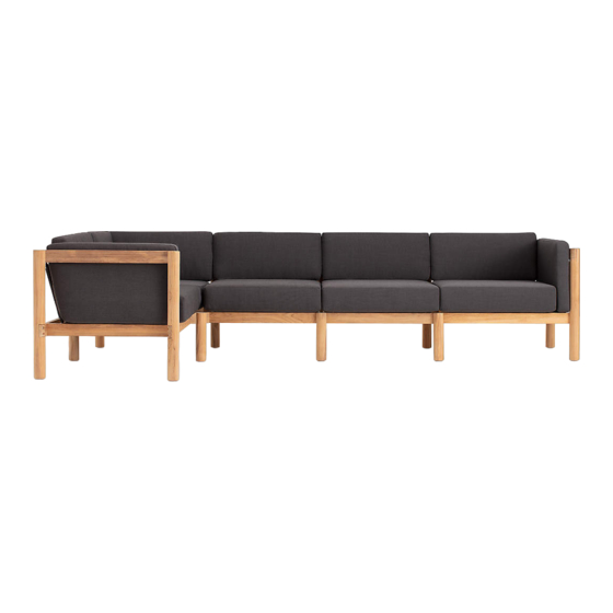
neighbor The 5-Piece Sectional Assembly Manual
Hide thumbs
Also See for The 5-Piece Sectional:
- Assembly manual (36 pages) ,
- Assembly manual (31 pages)
Advertisement
Quick Links
The 5-Piece
Sectional
Assembly Guide
B O X E S N E E D E D :
(1)
Left Arm Module Frame
(1)
Right Arm Module Frame
(2)
Armless Module Frame
(1)
Corner Module Frame
(1)
Left Arm Module Cushions
(1)
Right Arm Module Cushions
(2)
Armless Module Cushions
(1)
Corner Module Cushions
Advertisement

Related Manuals for neighbor The 5-Piece Sectional


Summary of Contents for neighbor The 5-Piece Sectional
- Page 1 The 5-Piece Sectional Assembly Guide B O X E S N E E D E D : Left Arm Module Frame Left Arm Module Cushions Right Arm Module Frame Right Arm Module Cushions Armless Module Frame Armless Module Cushions Corner Module Frame Corner Module Cushions...
- Page 2 Components Assembly Instructions Contact Parts Long Base Short Base Right Arm Corner Base Left Arm Left Arm Module Frame Box Armless Module Frame Box Right Arm Module Frame Box Corner Module Frame Box Left Arm Module Frame Box Right Arm Module Frame Box Small Roped Back Large Roped Back Corner Block Leg...
- Page 3 Components Assembly Instructions Contact Cushions Base Cushion Back Cushion Arm Cushion All Cushion Boxes Left Arm Module Cushion Box (1) Left Arm Module Cushion Box Right Arm Module Cushion Box (1) Right Arm Module Cushion Box Armless Module Cushion Box (2) Corner Base Cushion Large Corner Back Cushion Small Corner Back Cushion...
- Page 4 Components Assembly Instructions Contact Hardware Hex Bolt Long Hex Bolt Screw L-Bracket All Frame Boxes Corner Module Frame Box Left Arm Module Frame Box Left Arm Module Frame Box Right Arm Module Frame Box Right Arm Module Frame Box Tools Allen Wrench Phillips Head Screwdriver All Frame Boxes...
-
Page 5: Assembly Tips
Components Assembly Instructions Contact Assembly Tips Product Care • Spray on a mild cleaning solution of soap Exercise caution while lifting Caring for teak Two-person lift is recommended. Both the Unfinished teak will gradually change color (such as Woolite® or Dawn®) and water. boxes and the product itself are large and heavy from a honey gold to a silver-grey patina. - Page 6 The Haven Collection is designed to be easily adaptable to your space. The 5-Piece Sectional can be configured to be either left or right side facing. To build yours, choose the orientation you’d like by assembling in sections, starting at the Corner Module and work outwards toward the remaining module(s).
- Page 7 Components Assembly Instructions Contact Armless/ Corner...
- Page 8 Armless/Corner Components Assembly Instructions Contact Long Hex Bolt Fasten legs to corner base Using the Allen wrench, fasten two large legs and the assembled corner block leg onto the corner base with hex bolts. Use two long hex bolts when fastening corner Corner Block base to corner leg.
- Page 9 Armless/Corner Components Assembly Instructions Contact Fasten legs to left side of short base With the Allen wrench, thread two hex bolts through the holes in the front left side of the short base. Fasten to the short leg. Repeat this with the large leg on the back left corner of the small base.
- Page 10 Armless/Corner Components Assembly Instructions Contact Connect small base with corner base Gently slide small base into the grooves located on the large leg and corner block of the corner base. Align the holes located on the small base with the corresponding threaded holes on the corner base.
- Page 11 Armless/Corner Components Assembly Instructions Contact Fasten small base to corner base Secure the two bases by inserting four bolts through the holes on the small base. With the Allen wrench, gently fasten them to the four threaded holes located on the corner base.
- Page 12 Armless/Corner Components Assembly Instructions Contact Drain hole faced down Secure roped backs to bases Insert the lower brackets of the small roped back components into the slots of the short and corner base.
- Page 13 Armless/Corner Components Assembly Instructions Contact Attach back supports to roped backs Insert armless module back support and corner module back support onto the top brackets located on roped backs by inserting them into corresponding slots underneath the back supports.
- Page 14 Armless/Corner Components Assembly Instructions Contact Long Hex Bolt Fasten backs to large legs With your Allen wrench, gently fasten armless back support and corner module back support onto the threaded holes on the top of the large legs with hex bolts. Use two long hex bolts in the back in the far corner of the corner module back support.
- Page 15 Components Assembly Instructions Contact Left Arm/ Armless...
- Page 16 Left Arm/Armless Components Assembly Instructions Contact Connect large base to left arm Place the left arm component on a soft surface, verifying that the two screw holes inside the arm are facing upward. Gently insert the long base into the arm’s inner slots located on the inside of the two leg components.
- Page 17 Left Arm/Armless Components Assembly Instructions Contact Fasten large base to left arm Using the Allen wrench, fasten the large base to both leg components with four hex bolts.
- Page 18 Left Arm/Armless Components Assembly Instructions Contact Fasten small leg to large base Using the Allen wrench, fasten the small leg to the large base with two hex bolts. Be sure to leave two threaded holes on the small leg exposed as demonstrated.
- Page 19 Left Arm/Armless Components Assembly Instructions Contact Fasten large leg to large base Stand the base upright on its legs. Then with the Allen wrench, fasten the large leg to the large base with two hex bolts. Be sure to leave two threaded holes on the large leg exposed as demonstrated.
- Page 20 Left Arm/Armless Components Assembly Instructions Contact Connect large and small bases Gently slide small base into the slotted sections on the Left Arm Module’s large and small legs. Slide base until its pre-drilled holes align with the threaded holes on the legs.
- Page 21 Left Arm/Armless Components Assembly Instructions Contact...
- Page 22 Left Arm/Armless Components Assembly Instructions Contact Drain hole faced down Secure roped backs to large and small bases Insert the lower brackets of the corresponding roped back components into the slots of each base. The Left Arm Module (large base) will require the large roped back and the Armless Module (small base) will require the small roped back.
- Page 23 Left Arm/Armless Components Assembly Instructions Contact Attach back supports to roped backs Lower each back support onto the roped backs. The Left Arm Module (large base) will require the left arm back support and the Armless Module (small base) will require the small back support.
- Page 24 Left Arm/Armless Components Assembly Instructions Contact Fasten left arm back support to arm and large leg With your Allen wrench, gently fasten left arm back support onto large leg with two hex bolts. Repeat with adjoining side of small back support. Next, align the pre-drilled holes on the left arm with the holes on the L-bracket.
- Page 25 Components Assembly Instructions Contact Right Arm...
- Page 26 Right Arm Components Assembly Instructions Contact Connect large base to right arm Place the right arm component on a soft surface, verifying that the two screw holes are facing upward. Gently insert the long base into the arm’s inner slots.
- Page 27 Right Arm Components Assembly Instructions Contact Fasten large base to right arm Using the Allen wrench, fasten the large base to both legs of the right arm component with four hex bolts.
- Page 28 Right Arm Components Assembly Instructions Contact Connect large base to corner base Gently slide the assembly into the slotted sections on the corner block and large leg. Slide base until its pre-drilled holes align with the threaded holes on the corresponding legs.
- Page 29 Right Arm Components Assembly Instructions Contact Fasten large base to corner base After holes on the bases are aligned with the corresponding threaded holes on each leg, use the Allen wrench to fasten them together with two hex bolts on the front and back.
- Page 30 Right Arm Components Assembly Instructions Contact Drain hole faced down Secure roped back component Insert the lower brackets of the large roped back into the slots in the base. Make sure the drain holes are faced down toward the seat.
- Page 31 Right Arm Components Assembly Instructions Contact Attach back support to roped back Lower the Right Arm back support onto the roped back. Align slots underneath each back support with the corresponding roped back’s top bracket. Then insert bracket into the slot.
- Page 32 Right Arm Components Assembly Instructions Contact Fasten right arm back support to arm and large leg With your Allen wrench, gently fasten back support components onto large leg with two hex bolts. Next, align the pre-drilled holes on the right arm with the holes on the L-bracket.
- Page 33 Right Arm Components Assembly Instructions Contact Add cushions First with zipper seams facing backward, add arm cushions. Thread the cushion laces around the roped back posts and tie them down. Then add base cushions. Finally, add the two back cushions. Relax! You’re finished.
- Page 34 Components Assembly Instructions Contact Armless/ Right Arm...
- Page 35 Armless/Right Arm Components Assembly Instructions Contact Connect large base to right arm Place the right arm component on a soft surface, verifying that the two screw holes inside the arm are facing upward. Gently insert the long base into the arm’s inner slots located on the inside of the two leg components.
- Page 36 Armless/Right Arm Components Assembly Instructions Contact Fasten large base to right arm Using the Allen wrench, fasten the large base to both leg components with four hex bolts.
- Page 37 Armless/Right Arm Components Assembly Instructions Contact Fasten small leg to large base Using the Allen wrench, fasten the small leg to the large base with two hex bolts. Be sure to leave two threaded holes on the small leg exposed as demonstrated.
- Page 38 Armless/Right Arm Components Assembly Instructions Contact Fasten large leg to large base Stand the base upright on its legs. Then with the Allen wrench, fasten the large leg to the large base with two hex bolts. Be sure to leave two threaded holes on the large leg exposed as demonstrated.
- Page 39 Armless/Right Arm Components Assembly Instructions Contact Connect large and small bases Gently slide small base into the slotted sections on the Right Arm Module’s large and small legs. Slide base until its pre-drilled holes align with the threaded holes on the legs.
- Page 40 Armless/Right Arm Components Assembly Instructions Contact...
- Page 41 Armless/Right Arm Components Assembly Instructions Contact Drain hole faced down Secure roped backs to large and small bases Insert the lower brackets of the corresponding roped back components into the slots of each base. The Right Arm Module (large base) will require the large roped back and the Armless Module (small base) will require the small roped back.
- Page 42 Armless/Right Arm Components Assembly Instructions Contact Attach back supports to roped backs Lower each back support onto the roped backs. The Right Arm Module (large base) will require the right arm back support and the Armless Module (small base) will require the small back support.
- Page 43 Armless/Right Arm Components Assembly Instructions Contact Fasten right arm back support to arm and large leg With your Allen wrench, gently fasten right arm back support onto large leg with two hex bolts. Repeat with adjoining side of small back support. Next, align the pre-drilled holes on the right arm with the holes on the L-bracket.
- Page 44 Components Assembly Instructions Contact Corner/ Armless...
- Page 45 Corner/Armless Components Assembly Instructions Contact Long Hex Bolt Fasten legs to corner base Using the Allen wrench, fasten two large legs and the assembled corner block leg onto the corner base with hex bolts. Use two long hex bolts when fastening corner Corner Block base to corner leg.
- Page 46 Corner/Armless Components Assembly Instructions Contact Fasten legs to left side of short base With the Allen wrench, thread two hex bolts through the holes in the front right side of the short base. Fasten to the short leg. Repeat this with the large leg on the back right corner of the small base.
- Page 47 Corner/Armless Components Assembly Instructions Contact Connect small base with corner base Gently slide small base into the grooves located on the large leg and corner block of the corner base. Align the holes located on the small base with the corresponding threaded holes on the corner base.
- Page 48 Corner/Armless Components Assembly Instructions Contact Fasten small base to corner base Secure the two bases by inserting four bolts through the holes on the small base. With the Allen wrench, gently fasten them to the four threaded holes located on the corner base.
- Page 49 Corner/Armless Components Assembly Instructions Contact Drain hole faced down Secure roped backs to bases Insert the lower brackets of the small roped back components into the slots of the short and corner base.
- Page 50 Corner/Armless Components Assembly Instructions Contact Attach back supports to roped backs Insert armless module back support and corner module back support onto the top brackets located on roped backs by inserting them into corresponding slots underneath the back supports.
- Page 51 Corner/Armless Components Assembly Instructions Contact Long Hex Bolt Fasten backs to large legs With your Allen wrench, gently fasten armless back support and corner module back support onto the threaded holes on the top of the large legs with hex bolts. Use two long hex bolts in the back in the far corner of the corner module back support.
- Page 52 Components Assembly Instructions Contact Armless/ Right Arm...
- Page 53 Armless/Right Arm Components Assembly Instructions Contact Connect large base to right arm Place the right arm component on a soft surface, verifying that the two screw holes inside the arm are facing upward. Gently insert the long base into the arm’s inner slots located on the inside of the two leg components.
- Page 54 Armless/Right Arm Components Assembly Instructions Contact Fasten large base to right arm Using the Allen wrench, fasten the large base to both leg components with four hex bolts.
- Page 55 Armless/Right Arm Components Assembly Instructions Contact Fasten small leg to large base Using the Allen wrench, fasten the small leg to the large base with two hex bolts. Be sure to leave two threaded holes on the small leg exposed as demonstrated.
- Page 56 Armless/Right Arm Components Assembly Instructions Contact Fasten large leg to large base Stand the base upright on its legs. Then with the Allen wrench, fasten the large leg to the large base with two hex bolts. Be sure to leave two threaded holes on the large leg exposed as demonstrated.
- Page 57 Armless/Right Arm Components Assembly Instructions Contact Connect large and small bases Gently slide small base into the slotted sections on the Right Arm Module’s large and small legs. Slide base until its pre-drilled holes align with the threaded holes on the legs.
- Page 58 Armless/Right Arm Components Assembly Instructions Contact...
- Page 59 Armless/Right Arm Components Assembly Instructions Contact Drain hole faced down Secure roped backs to large and small bases Insert the lower brackets of the corresponding roped back components into the slots of each base. The Right Arm Module (large base) will require the large roped back and the Armless Module (small base) will require the small roped back.
- Page 60 Armless/Right Arm Components Assembly Instructions Contact Attach back supports to roped backs Lower each back support onto the roped backs. The Right Arm Module (large base) will require the right arm back support and the Armless Module (small base) will require the small back support.
- Page 61 Armless/Right Arm Components Assembly Instructions Contact Fasten right arm back support to arm and large leg With your Allen wrench, gently fasten right arm back support onto large leg with two hex bolts. Repeat with adjoining side of small back support. Next, align the pre-drilled holes on the right arm with the holes on the L-bracket.
- Page 62 Components Assembly Instructions Contact Left Arm...
- Page 63 Left Arm Components Assembly Instructions Contact Connect large base to left arm Place the left arm component on a soft surface, verifying that the two screw holes are facing upward. Gently insert the long base into the arm’s inner slots.
- Page 64 Left Arm Components Assembly Instructions Contact Fasten large base to left arm Using the Allen wrench, fasten the large base to both legs of the left arm component with four hex bolts.
- Page 65 Left Arm Components Assembly Instructions Contact Connect large base to corner base Gently slide the assembly into the slotted sections on the corner block and large leg. Slide base until its pre-drilled holes align with the threaded holes on the corresponding legs.
- Page 66 Left Arm Components Assembly Instructions Contact Fasten large base to corner base After holes on the bases are aligned with the corresponding threaded holes on each leg, use the Allen wrench to fasten them together with two hex bolts on the front and back.
- Page 67 Left Arm Components Assembly Instructions Contact Drain hole faced down Secure roped back component Insert the lower brackets of the large roped back into the slots in the base. Make sure the drain holes are faced down toward the seat.
- Page 68 Left Arm Components Assembly Instructions Contact Attach back support to roped back Lower the Left Arm back support onto the roped back. Align slots underneath each back support with the corresponding roped back’s top bracket. Then insert bracket into the slot.
- Page 69 Left Arm Components Assembly Instructions Contact Fasten left arm back support to arm and large leg With your Allen wrench, gently fasten back support components onto large leg with two hex bolts. Next, align the pre-drilled holes on the left arm with the holes on the L-bracket.
- Page 70 Left Arm Components Assembly Instructions Contact Add cushions First with zipper seams facing backward, add arm cushions. Thread the cushion laces around the roped back posts and tie them down. Then add base cushions. Finally, add the two back cushions. Relax! You’re finished.
- Page 71 Components Assembly Instructions Contact Contact Have a question, comment, feedback? We love hearing from customers. support@hineighbor.com hineighbor.com...