Table of Contents
Advertisement
Quick Links
INSTRUCTION MANUAL
MULTIBAND FM TRANSCEIVER
iT90A
This device complies with Part 15 of the FCC Rules. Operation is sub-
ject to the following two conditions: (1) This device may not cause
harmful interference, and (2) this device must accept any interference
received, including interference that may cause undesired operation.
WARNING: MODIFICATION OF THIS DEVICE TO RECEIVE CEL-
LULAR RADIO TELEPHONE SERVICE SIGNALS IS PROHIBITED
UNDER FCC RULES AND FEDERAL LAW.
Advertisement
Table of Contents

Related Manuals for Icom IC-T90A


Summary of Contents for Icom IC-T90A
- Page 1 INSTRUCTION MANUAL MULTIBAND FM TRANSCEIVER iT90A This device complies with Part 15 of the FCC Rules. Operation is sub- ject to the following two conditions: (1) This device may not cause harmful interference, and (2) this device must accept any interference received, including interference that may cause undesired operation.
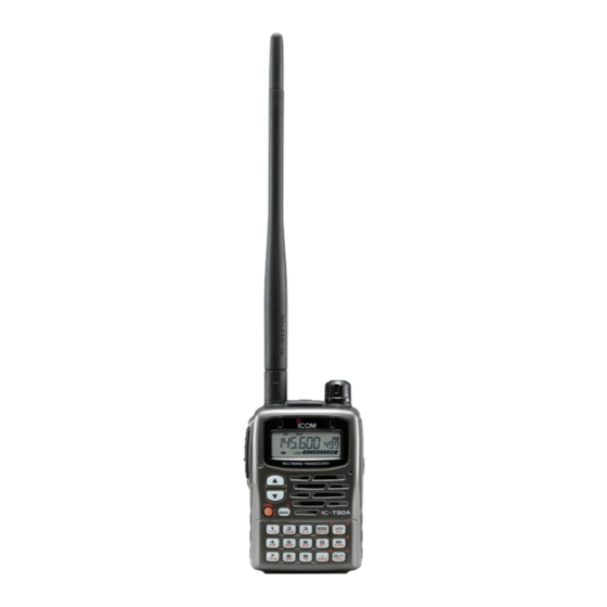
- Page 2 The IC-T90A is a tri-band, 50 MHz, 144 MHz, 430 (440) MHz FM transceiver that offers a wide-band AM, FM and WFM scanning receiver. Not only you can hear your favorite TV...
-
Page 3: Important
If disregarded, inconvenience only. No risk NOTE of personal injury, fire or electric shock. Icom, Icom Inc. and the logo are registered trademarks of Icom Incorporated (Japan) in the United States, the United Kingdom, Germany, France, Spain, Russia and/or other countries. SUPPLIED ACCESSORIES Accessories included with the transceiver: q Li-Ion battery pack (BP-217) ... -
Page 4: Cautions
Otherwise, the battery pack or installed batteries will become exhausted. For U.S.A. only CAUTION: pressly approved by Icom Inc., could void your authority to operate this device under FCC regulations. Changes or modifications to this device, not ex-... -
Page 5: Table Of Contents
TABLE OF CONTENTS FOREWORD ... i IMPORTANT ... ii EXPLICIT DEFINITIONS ... ii SUPPLIED ACCESSORIES ... ii CAUTIONS ... iii TABLE OF CONTENTS ... iv QUICK REFERENCE GUIDE ... 1 – 6 PANEL DESCRIPTION ... 7 – 12 I Panel description ... 7 I Function display ... -
Page 6: Quick Reference Guide
QUICK REFERENCE GUIDE I Installing the battery pack q Open the latch. Then, attach the BP-217 Li-Ion battery pack or BP-216 optional battery case. • Be sure to observe the correct direction. • Charge Li-Ion battery pack before use. w Lock the latch. NOTE: The battery pack is provided uncharged. - Page 7 If the transceiver accidentally dropped and the swivel belt clip’s stopper is scratched, the swivel belt clip may not work properly. iC-t90a D Handstrap Slide the handstrap through the loop on the top of the belt clip as shown at right.
-
Page 8: Attaching The Antenna
QUICK REFERENCE GUIDE D Attaching the antenna Insert the supplied wide band antenna into the antenna con- nector and screw down the antenna as shown below. • 50 MHz band adapter Attach the 50 MHz band antenna adapter before operating on or receiving the signal below the 50 MHz band. - Page 9 I Charging the Li-Ion battery pack D Charging with the wall charger IC-T90A with BP-217 BC-110AR/D/DR DC power jack q Push and hold [PWR] to turn the transceiver power OFF. w Insert the charger plug into the DC power jack of the trans- ceiver.
- Page 10 QUICK REFERENCE GUIDE I Rapid charging The optional BC-139 provides rapid charging of the battery pack. CAUTION: To avoid damage to the transceiver, turn the transceiver OFF while charging. • Charging period: 2.5 hours (w/BP-217) Turn power OFF. to AC outlet BC-123 (supplied with...
-
Page 11: Quick Reference Guide ........ 1
I Your first contact Now that you have your IC-T90A ready to operate, you are probably excited to get on the air. We would like to take you through a few basic operation steps to make your first “On The Air” an enjoyable experience. -
Page 12: Panel Description
PANEL DESCRIPTION I Panel description Keypad !6 – @5 q POWER SWITCH [PWR] Push for 1 sec. to turn the transceiver power ON and OFF. w BAND SWITCH [BAND] ➥ Push to select the operating band (5 MHz, Air, VHF, UHF, etc.). - Page 13 y PTT SWITCH [PTT] ➥ Push and hold to transmit in 50/144/430 (440) MHz am- ateur bands; release to receive. (p. 28) • When WFM or AM mode is selected, transmission is impossi- ble. u ANTENNA CONNECTOR (p. 3) Connects the supplied antenna. i EXTERNAL SPEAKER AND MICROPHONE JACKS [SP/MIC] Connects an optional speaker-microphone or headset, if...
- Page 14 PANEL DESCRIPTION ➥ While pushing [PTT], this key sends a DTMF “B”. !4 CALL/LOCK SWITCH [CALL/TV LOCK] ➥ Toggles between call channel, TV channel, weather channel (U.S.A. version only) and CALL/TV LOCK VFO mode in sequence. (p. 20) ➥ Push for 1 sec. to toggle the lock function ON and OFF. (p.
- Page 15 @0 FREQUENCY SKIP SWITCH [5 SKIP] ➥ Push for 1 sec. to turn the frequency skip func- tion ON and OFF in VFO mode. (p. 47) SKIP • “P SKIP” appears when the frequency skip function is in use. ➥ Push for 1 sec. to set the memory channel as the fol- lowing skip channel in memory mode in order.
-
Page 16: I Function Display
PANEL DESCRIPTION I Function display q FREQUENCY READOUT Shows the operating frequency, set mode contents, etc. • The smaller “75,” “50” and “25” to the right of the readout indi- cate 0.75, 0.5 and 0.25 kHz, respectively. • The decimal point of the frequency blinks during scan. w LOCK INDICATOR (p. - Page 17 t TONE INDICATORS (p. 70) ➥ Appears when the following tone functions are activated. • Subaudible tone encoder — “T” appears. (p. 29) • Tone squelch — “T SQL” appears. (p. 71) • Pocket beep — “T SQLS” appears. (p. 71) •...
-
Page 18: Battery Charging
ON overnight. Then, fully charge the battery pack again. If the battery pack still does not retain a charge (or very little), a new battery pack must be purchased. Use Icom battery packs, chargers and cables only. The use of Latch non-Icom products may impair transceiver performance and invalidate the warranty. -
Page 19: I Regular Charging
Be sure to turn the transceiver power OFF. e Connect the AC adapter* (BC-110AR/D/DR) as shown below. * Not supplied with some versions. r Remove any cables from the [DC11V] jack. • Charging period: 15 hours (w/BP-217) IC-T90A with BP-217 BC-110AR/D/DR CP-19 (optional) DC power jack... -
Page 20: I Rapid Charging
BATTERY CHARGING I Rapid charging The optional BC-139 provides rapid charging of the battery pack. • Charging period: 2.5 hours (w/BP-217) CAUTION: To avoid damage to the transceiver, turn it OFF while charging. • Recommended temperature range for charging: +32°F to +95°F; 0°C to +35°C •... -
Page 21: I Battery Case
I Battery case (Option) q Install 2 R6 (AA) size alkaline batteries into the optional BP-216 BATTERY CASE • Be sure to observe the correct polarity. w Install the battery case as shown at right. A build in step-up convertor in the BP-216 increases the volt- age up to 5 V DC. -
Page 22: Basic Operation
(p. 13) w Push [PWR] for 1 sec. to turn the power ON. • The function display shows “ICOM,” current voltage then the op- erating frequency. • Repeat this step to turn power OFF. -
Page 23: I Tuning Step
I Tuning step When using the tuning dial to change the frequency, or when a scan function is activated, the frequency changes in increments determined by the set tun- ing step. Tuning steps can be selected for each band. This transceiver has 13 tuning steps as follows: •... -
Page 24: I Setting A Frequency
BASIC OPERATION I Setting a frequency Push numeral keys and [•] to input the desired frequency. • Frequency can be set irrelevant of the se- lected band. • When inputting a frequency outside of the frequency range, the previously selected frequency is automatically selected after in- putting 1 kHz digit. -
Page 25: I Mode Selection
I Mode selection D VFO mode VFO mode is used for setting a desired frequency within the band range. ➥ Push [VFO] to select VFO mode. • Pushing [VFO] in VFO mode toggles VFO A and B. What is VFO? VFO is an abbreviation of Variable Fre- quency Oscillator. -
Page 26: I Operating Band And Receive Mode Selection
BASIC OPERATION I Operating band and receive mode selection D Selecting the operating band The transceiver can receive the BC (broadcast) bands, 5 MHz band, 50 MHz band, FM broadcast band, Air band, VHF (144 MHz) band, 220 MHz band, 300 MHz band, UHF (430MHz) band or 800 MHz band. -
Page 27: I Setting The Squelch Level
I Setting the squelch level The squelch circuit mutes the received audio signal depending on the signal strength. The transceiver has 9 squelch levels, a continuously open setting and an automatic squelch setting. D Setting the squelch level q While pushing and holding [SQL], ro- tate [DIAL] one-click to display the current squelch level. -
Page 28: I Receiving
BASIC OPERATION I Receiving D Setting volume level ➥ Push [Y] or [Z] to set the desired audio level. • Rotating the tuning dial while pushing [Y] or [Z] also sets the audio level. D Setting squelch level q While pushing [SQL], rotate [DIAL] to select the squelch level. - Page 29 D Receiving FM broadcast [EXAMPLE]: Receiving 88.200 MHz. q Select VFO mode with [VFO]. w For direct frequency input, push [8], [8], [•], [2], [0], [0]. • Skip e and t in this case. e Push [BAND] several times to select the FM broadcast band.
- Page 30 BASIC OPERATION D Receiving TV channels Available TV channels depends on the version. Refer to the TV frequency table (p. 83) for details. Some channels are set as skip channels. Refer to the skip channel setting (p. 26) for details. TV channel frequency and skip setting can be re-pro- grammed via the CS-T90A cloning software, ask your dealer for details.
- Page 31 D TV skip scan The transceiver automatically programs the receivable TV channels as non-skip channels and others as skip channels. q Select TV mode with [CALL/TV]. • Pushing [CALL/TV] selects a call, TV and weather channel (U.S.A. version only) in sequence. w Push [MODE SCAN] for 1 sec.
-
Page 32: I Rit Function
BASIC OPERATION I RIT function To compensate for the off frequency of a transmitting station, the transceiver has receive incremental tuning for receiving fre- quencies above 630.000 MHz. The RIT function cannot be used in TV mode and is automatically cancelled below 630.000 MHz. The receive incremental tuning (RIT) shifts only the receive frequency within approx. -
Page 33: I Transmitting
I Transmitting D Amateur band operation CAUTION: Transmitting without an antenna may damage the trans- ceiver. Make sure a charged battery pack or al- kaline batteries are installed. (p. 1) [DIAL] [PTT] Microphone [BAND] Lights red while [3 H/L] transmitting IMPORTANT: To maximize the read- ability of your transmitted signal, pause a few sec. -
Page 34: I Repeater Operation
BASIC OPERATION I Repeater operation When using a repeater, the transmit frequency is shifted from the receive frequency by the offset frequency. (p. 31) It is con- venient to program repeater information into memory chan- nels. (p. 37) Repeater 434.340 MHz 439.340 MHz Station A q Set the receive frequency (repeater output frequency). -
Page 35: D Checking The Repeater Input Signal
D Checking the repeater input signal The transceiver can check whether the other station’s trans- mit signal can be received directly or not. ➥ Push and hold [SQL] to check whether the other station’s transmit signal can be directly received or not. •... -
Page 36: I Duplex Operation
BASIC OPERATION I Duplex operation D Setting offset frequency When communicating through a repeater, the transmit fre- quency is shifted from the receive frequency by an amount determined by the offset frequency. q Select VFO mode or desired memory channel to be pro- grammed. -
Page 37: I Split Operation
I Split operation Split frequency operation allows you to transmit and receive on two different frequencies in the same band. The split fre- quency operation is performed using 2 frequencies, one in VFO A and one in B. D Setting split frequency operation q Push [8 SET] for 1 sec. -
Page 38: I Auto Repeater Function
BASIC OPERATION I Auto repeater function (U.S.A. and Korea versions only) The U.S.A. and Korea versions automatically activate the re- peater settings (duplex ON/OFF, duplex direction, tone en- coder ON/OFF) when the operating frequency falls within or outside of the general repeater output frequency range. The offset and repeater tone frequencies are not changed by the auto repeater function, reset these frequencies, if necessary. -
Page 39: I 1750 Hz Tone
I 1750 Hz tone Some European repeaters require a 1750 Hz tone to be ac- cessed. For such European repeaters, perform the following. • This tone can be use as a ‘Call signal’ in countries out of Europe. q Push [• DTMF.M] for 1 sec. to select DTMF memory. w Rotate [DIAL] counter-clockwise until “T-CALL”... -
Page 40: Memory/Call Channels
MEMORY/CALL CHANNELS I General The transceiver has 500 memory channels, 50 scan edge channels and 5 call channels for storage of often-used fre- quencies. Memory channels can be named with 6 characters and as- signed to 18 banks. D Memory/call channel contents The following information can be programmed into memory or call channels: •... -
Page 41: I Calling Up Memory Channels
I Calling up memory channels Memory channels can be selected with the [DIAL] and keypad. • Blank channels cannot be selected via [DIAL]. • Blank channels can be selected via key- pad. • Previously selected channels appear when the wrong memory channel num- ber is entered. -
Page 42: I Programming Memory Channels
MEMORY/CALL CHANNELS I Programming memory channels Program the desired frequency into a memory channel, call channel or scan edge channel as follows. The memory channels are shared with all bands. Memory channels 003–499 are blank (non-programmed) channels as a factory setting. q, w Set the frequency. -
Page 43: I Transferring Memory Contents
D Auto memory channel increment While programming a memory channel, the next memory channel can be selected automatically. This is convenient when programming memory channels one after another. ➥ Keep pushing [MR S.MW] for 2 sec. or more, at step t of the left section, to select the next memory channel auto- matically. -
Page 44: I Copying Memory Contents
MEMORY/CALL CHANNELS I Copying memory contents This is convenient when programming memory contents into a scan edge channel or call channel. • Call or scan edge channel contents can be copied in the same manner. q Push [MR S.MW] to select memory mode. w Select the memory channel to be copied with [DIAL]. -
Page 45: Memory Name Indication
t Rotate the tuning dial to select the desired character. • See the following list for available characters. y Push [BAND] to advance the cursor. • Rotating the tuning dial while pushing [BAND] also selects the cursor. u Repeat t and y until the desired name is input. i Push [VFO] to program the name. -
Page 46: I Memory Bank
MEMORY/CALL CHANNELS I Memory bank The transceiver has 500 memory channels that can be as- signed to 18 banks for faster memory access, memory arrangement, etc. Each bank (A–H, J, L, N–R, T, U and Y) can be assigned up to 100 memory channels. - Page 47 VFO mode Release [CALL/TV]. SKIP t Push [BAND] to select memory bank. q Push [MR] to select memory mode. y Rotate [DIAL] to select memory bank channel. w Select Mch with [DIAL]. Memory bank and channel. e Push [MR S.MW] for 1 sec. to u Push [VFO].
-
Page 48: I Memory Clear
MEMORY/CALL CHANNELS I Memory clear Unwanted memory channels can be cleared (erased). Before clearing a memory channel make sure it is no longer needed as cleared memories cannot be recalled. Scan edges (0A/0B) cannot be cleared. q Push [MR S.MW] for 1 sec. to indicate a memory channel. •... -
Page 49: I Call Channel
I Call channel 5 call channels are available to store the most-often-used fre- quencies for quick recall. The call channels can be programmed in a similar manner to memory channel programming. ➥ Select C0–C4 for programming call channels 0–4 in step r in “Programming memory channels.”... -
Page 50: Scan Operation
SCAN OPERATION I Scan types D VFO scans FULL SCAN (p. 46) Lower Upper edge edge Scan P SKIP P SKIP Jump BAND SCAN (p. 46) Lower Upper band edge band edge Scan Start Jump PROGRAMMED SCAN (p. 46) Lower Upper scan edge scan edge... -
Page 51: I Vfo Scan
I VFO scan The following scans are available for the VFO scan. FULL SCAN Repeatedly scans all frequencies over the entire receive range. • Some frequency ranges are restricted depending on versions. BAND SCAN Repeatedly scans all frequencies over the entire selected band. -
Page 52: I Frequency Skip Function
SCAN OPERATION I Frequency skip function Unwanted frequencies can be skipped and programmed as skip channels when full scan, band scan or programmed scan is pausing. q Start a VFO scan. (p. 46) w While receiving an unwanted signal and scan pauses, push [5 SKIP] for 1 sec. -
Page 53: I Memory Scan
I Memory scan Memory scan repeatedly scans all memory channels except skip channels. There are 3 types of memory scan, select band scan, full bank scan and bank scan are available. D Full memory scan/Select band scan q Push [MR] to enter memory mode. w While pushing and holding [MODE SCAN], rotate [DIAL] to select from scan-guidance, [ALL], [SEL BC], [SEL 5], [SEL 50], [SEL WFM], [SEL AIR], [SEL 144], [ SEL 220], [SEL... -
Page 54: I Scan Notes
SCAN OPERATION I Scan notes D Squelch setting Scanning stops when the squelch opens. Make sure the squelch is set to the threshold point or desired squelch level. ➥ Rotate the tuning dial while pushing [SQL] to select auto- matic squelch (AUTO) or a level (1–9) where the noise is muted. -
Page 55: Priority Watch
I Priority watch types Priority watch checks for signals on a frequency every 5 sec. while operating on a VFO frequency or scan. The transceiver has 6 priority watch types to suit your needs. The watch resumes according to the selected scan resume condition. -
Page 56: I Priority Watch Operation
PRIORITY WATCH I Priority watch operation D Memory channel watch While operating on a VFO frequency, priority watch checks for a signal in the selected memory channel every 5 sec. • A memory channel with skip information can be watched. q Select VFO mode;... - Page 57 D VFO scan with memory channel watch While scanning in VFO mode, priority watch checks for sig- nals in the selected memory channel every 5 sec. • A memory channel with skip information can be watched. q Select the desired memory channel to be watched. w Select VFO mode.
- Page 58 PRIORITY WATCH D VFO scan with memory scan watch While scanning in VFO mode, priority watch checks for sig- nals in memory channels every 5 sec. q Select memory mode. w Push [MODE SCAN] for 1 sec. to start a memory scan. •...
- Page 59 D VFO scan with call channel watch While scanning in VFO mode, priority watch checks for sig- nals in the selected call channel every 5 sec. q Select VFO mode. w Push [CALL/TV] to select call channel mode. e Rotate [DIAL] to select the desired call channel. r Push [8 SET] for 1 sec.
-
Page 60: Set Mode
SET MODE I Set mode Set mode is used for programming in- frequently changed values or conditions of functions. In addition, this transceiver has 2 ex- panded set modes which are used for programming even more infrequently changed values or conditions of func- tions. -
Page 61: I Set Mode Items
I Set mode items Set mode is used for programming infrequently changed val- ues or conditions of functions. General set mode R TONE Repeater tone (p. 57) C TONE Tone squelch/pocket beep frequency (p. 57) CODE DTCS squelch code (p. 57) OFFSET Offset frequency (p. - Page 62 SET MODE • Repeater tone Selects the tone encoder frequency for accessing a repeater, etc. from one of 50 available tone frequencies. • 67.0–254.1 Hz (50 tones): 88.5 Hz (default) •Tone squelch/pocket beep frequency (C TONE) Selects the tone squelch or pocket beep frequency from one of 50 available tone frequencies.
- Page 63 • Scan resume time Selects the scan resume time of a paused frequency after the received signal disappears. • 0 Scan resumes when a received signal disappears. • 1–5 Scan pauses 1–5 sec. after a received signal disappears. (default: 2 sec.) •...
- Page 64 SET MODE • Beep tone Turns the confirmation beep ON or OFF. • ON The confirmation beep is turned ON. (default) • OFF The confirmation beep is turned OFF. • Display backlighting The transceiver has display backlighting with a 5 sec. timer for nighttime operation.
- Page 65 • Power save The power save function reduces the current drain to con- serve battery power. This item sets the power save duty cycle—the ratio of receive circuit on to receive circuit off while standing by. The duty cycle can be set to automatic (default), 1:1, 1:4, 1:8, 1:16 or OFF.
- Page 66 SET MODE • Auto repeater The auto repeater function automatically turns ON or OFF the duplex operation with specified shift direction and tone en- coder, when the operating frequency falls within or outside of the general repeater output frequency range. U.S.A.
- Page 67 • Weather Alert (USA version only) Turns the weather alert function ON or OFF. • ON The WX alert beep sounds when alert signal received. • OFF The WX alert beep does not sound. (default) • Scan stop beep Turns the scan stop beep ON or OFF. •...
- Page 68 SET MODE • Backlighting color Selects the backlighting color between green, orange or red. • Turn the expanded set mode 1 ON in advance. • GREEN Green backlighting color. (default) • ORANGE Orange backlighting color. • RED Red backlighting color. •...
- Page 69 • PTT lock Turns the PTT lock ON or OFF. • Turn the expanded set mode 1 ON in advance. • ON The PTT lock is turned ON. • OFF The PTT lock is turned OFF. (default) • LCD contrast The contrast of the LCD can be adjusted from 4 levels.
- Page 70 SET MODE • DTCS phase mode Selects the DTCS phase mode. • Turn the expanded set mode 2 ON in advance. • BOTH N Normal phases are used for both Tx and Rx. (default) • TN-RR Normal phase is used for Tx;...
- Page 71 • Split operation Turns the split operation ON or OFF. Split frequency opera- tion allows you to transmit and receive on two different fre- quencies. Split frequency operation uses 2 frequencies, one in VFO A and the other in VFO B. •...
-
Page 72: Other Functions
OTHER FUNCTIONS I Programming a DTMF code DTMF codes are used for autopatching, accessing repeaters, controlling other equipment, etc. The transceiver has 10 DTMF memory channels (D0–D9) for storage of often-used DTMF codes of up to 16 digits. q Push [• DTMF.M] for 1 sec. to enter DTMF memory. w Rotate [DIAL] to select the desired DTMF memory chan- nel. -
Page 73: I Transmitting A Dtmf Code
I Transmitting a DTMF code D Transmitting from DTMF memory The selected DTMF code is transmitted at each push of the [SQL] switch while transmitting. The rate at which DTMF memories send individual DTMF characters can be set in set mode. (p. 61) q Set the desired frequency. -
Page 74: I Clearing A Dtmf Memory
OTHER FUNCTIONS I Clearing a DTMF memory An unwanted DTMF memory can be cleared (erased). q Push [• DTMF.M] for 1 sec. to enter DTMF memory mode. w Rotate [DIAL] to select the desired DTMF memory chan- nel to be cleared. e Push [•... -
Page 75: I Tone Frequency And Dtcs Code
I Tone frequency and DTCS code • Subaudible (repeater) tone Some repeaters require subaudible tones to be accessed. Subaudible tones are superimposed over your nor- mal signal and must be set in advance. • Tone and DTCS squelches The tone squelch (CTCSS) or DTCS squelch opens only when receiving a signal containing a matching subaudi- ble tone or DTCS code, respectively. -
Page 76: I Tone/Dtcs Squelch
OTHER FUNCTIONS I Tone/DTCS squelch q Set the desired operating frequency, CTCSS tone and DTCS code. w Push [2 TONE] for 1 sec. one or more times to activate the tone or DTCS squelch. (T SQL or DTCS) • Subaudible tone encoder “T,” tone squelch “T SQL,” pocket beep “T SQLS,”... -
Page 77: I Available Tone Frequencies
I Available tone frequencies The transceiver has 50 tone frequencies for repeater and tone squelch (CTCSS)/pocket beep operation. Separate tone frequencies can be set for repeater and tone squelch/pocket beep operation. 67.0 82.5 100.0 123.0 151.4 171.3 69.3 85.4 103.5 127.3 156.7 173.8... -
Page 78: I Tone Scan
OTHER FUNCTIONS I Tone scan The transceiver can detect the subaudible tone frequency and DTCS code in a received signal. By monitoring a signal that is being transmitted on a repeater input frequency, you can determine the tone frequency required to access the repeater. q Set the desired frequency or memory channel to be checked for a tone frequency or DTCS code. -
Page 79: I Beep Tones
I Beep tones You can select to have confirmation beeps sound at the push of a switch. The output level can be adjusted within 32 levels or to the related level of the volume. (p. 58) You can select silent operation by turning beep tones OFF. (p. -
Page 80: I Morse Code Synthesizer
OTHER FUNCTIONS I Morse code synthesizer The transceiver announces the operating frequency or TV channel number in Morse code. The keying speed can be ad- justed within 10 to 25 WPM in 5 WPM steps for your conve- nience. This can be selected in expanded set mode 2. (p. 66) [PWR] [BAND] [CALL/TV]... -
Page 81: I Time-Out Timer
I Time-out timer To prevent accidental prolonged transmission, etc., the trans- ceiver has a time-out timer. This timer cuts a transmission OFF after 1, 3, 5 or 10 min. of continuous transmission. This timer can be cancelled (default). Approx. 10 sec. before the time-out timer is activated, the transceiver emits a beep tone as a warning. -
Page 82: I Weather Channel Operation
OTHER FUNCTIONS I Weather channel operation (USA version only) There are 10 weather channels for moni- toring weather channels from the NOAA (National Oceanographic and Atmospheric Administration) broadcasts. D D Weather channel selection q Push [ CALL/TV LOCK ] one or two times to select weather channel mode. - Page 83 OTHER FUNCTIONS NOTE: While receiving a signal (on a frequency other than the weather alert ON frequency), the receiving signal or audio will be interrupted momentarily every 5 sec. (approx.) in the case that the alert function is turned ON. This symp- tom is caused by the WX alert function.
-
Page 84: I Cloning Function
I Cloning function The IC-T90A has transceiver-to-transceiver data cloning ca- pability. This function is useful when you want to copy all of the programmed contents from one IC-T90A to another. • An optional OPC-474 CLONING CABLE q Connect an optional OPC-474 between both [SP] jacks. -
Page 85: I Resetting
I Resetting The function display may occasionally display erroneous information (e.g. when first applying power). This may be caused externally by static electricity or by other factors. If this problem occurs, turn power OFF. After waiting a few seconds, turn power ON again. -
Page 86: Hm-75A Remote Control Microphone
HM-75A REMOTE CONTROL MICROPHONE The optional HM-75A allows you to remotely select operating frequencies, memory channels, etc. Remote control functions can be selected from 3 settings. These can be selected in set mode. (p. 61) Transmit LED PTT switch LOCK The HM-75A has a lock switch on the backside to prevent ac- cidental frequency changes, etc. -
Page 87: Troubleshooting
If your transceiver seems to be malfunctioning, please check the following points before sending it to a service center. PROBLEM POSSIBLE CAUSE No power comes ON. • The batteries are exhausted. • The battery polarity is reversed. No sound comes from the •... -
Page 88: Tv Frequency Table
TV FREQUENCY TABLE The following tables show the channels versus video and audio frequencies depending on each version. I U.S.A. channels Video Audio 55.25 59.75 61.25 65.75 67.25 71.75 77.25 81.75 83.25 87.75 175.25 179.75 181.25 185.75 187.25 191.75 193.25 197.75 199.25 203.75... - Page 89 I Australian channels Video Audio Video 46.25 727.25 732.75 57.25 735.25 740.75 64.25 743.25 748.75 86.25 751.25 756.75 95.25 759.25 764.75 102.25 767.25 772.75 138.25 775.25 780.75 175.25 783.25 788.75 182.25 791.25 796.75 189.25 799.25 804.75 196.25 209.25 807.25 812.75 216.25 815.25 820.75...
- Page 90 TV FREQUENCY TABLE I China channels Video Audio 49.75 56.25 57.75 64.25 65.75 72.25 77.25 83.75 85.25 91.75 168.25 174.75 176.25 182.75 184.25 190.75 192.25 198.75 200.25 206.75 208.25 214.75 216.25 222.75 471.25 477.75 479.25 485.75 487.25 493.75 495.25 501.75 503.25 509.75 511.25...
- Page 91 I Italian channels Video Audio Video 823.25 828.75 53.75 831.25 836.75 62.25 839.25 844.75 82.25 847.25 852.75 175.25 855.25 860.75 183.25 192.25 201.25 210.25 217.25 224.25 471.25 479.25 487.25 495.25 503.25 511.25 519.25 527.25 535.25 543.25 551.25 559.25 567.25 575.25 583.25 591.25 599.25...
-
Page 92: Specifications
SPECIFICATIONS D General • Frequency coverage Transmit U.S.A 50–53.995, Canada 144–148, 430–450* Asia 50–53.995, 144–148, 430–440 Australia 50–53.995, 144–148, 420–450* Korea 50–53.995, 144–146, 430–440 Taiwan 50–50.2, 144–146, 430–432 General 50–53.995, 144–148, 430–440 Guaranteed 440–450 MHz only Guaranteed 430–440 MHz only •... -
Page 93: Specifications ..................... 87
D Receiver • Receive system : Double-conversion superheterodyne • Intermediate frequencies : 1st 69.45 MHz (FM/AM) 13.35 MHz (WFM) 450 kHz • Sensitivity (except spurious points; typical values): 1.625–4.995 MHz (at 12 dB SINAD) 5.000–49.995 MHz 50.000–54.000 MHz 54.005–143.995 MHz 144.000–148.000 MHz 0.16 µV 148.005–221.995 MHz 0.4 µV 222.000–225.000 MHz 0.32 µV... -
Page 94: Options
OPTIONS AD-92SMA ANTENNA CONNECTOR ADAPTER Allows you to connect an antenna with a BNC connector. (SMA to BNC adapter) BC-110AR/D/DR WALL CHARGER Regularly charges BP-217 Li-ion battery pack in 15 hrs. BC-139 DESKTOP CHARGER Rapidly charges BP-217 Li-ion battery pack in 2 hrs. and 30 min. - Page 95 Flexible boom micro- VS-1 phone and rotating ear- piece with a spring earhook. SP-13 EARPHONE Provides clear receive audio in noisy environ- ments. LC-152A CARRYING CASE Helps protect the transceiver from scratches, etc. CP-19 CIGARETTE LIGHTER CABLE WITH NOISE FILTER Used for operation and charging a battery pack connected to the transceiver via a DC power source.
- Page 96 Blank page...
-
Page 97: Pocket Guide
POCKET GUIDE Important operating instructions are summed up in this and the following page for your simple reference. By cutting along the line and folding on the dotted line, it will become a card sized operating guide which can easily be carried in a card case or wallet, etc. - Page 98 QUICK REFERENCE...
- Page 100 Count on us! A-6134H-1EX Printed in Japan 1-1-32 Kamiminami, Hirano-ku, Osaka 547-0003 Japan © 2002 Icom Inc.