Table of Contents
Advertisement
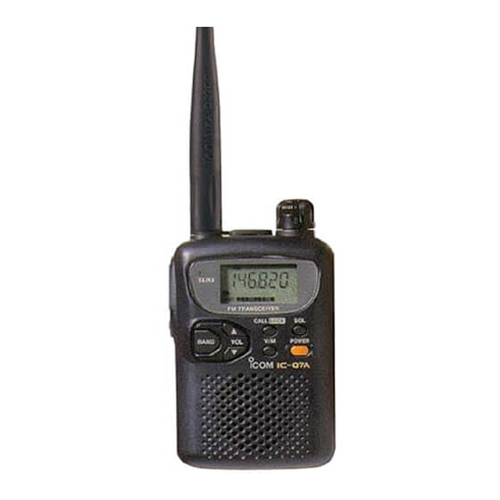
INSTRUCTION MANUAL
DUAL BAND FM TRANSCEIVER
iQ7A
iQ7E
This device complies with Part 15 of the FCC rules. Operation is sub-
ject to the following two conditions: (1) This device may not cause
harmful interference, and (2) this device must accept any interference
received, including interference that may cause undesired operation.
Advertisement
Table of Contents

Related Manuals for Icom IC-Q7A


Summary of Contents for Icom IC-Q7A
- Page 1 INSTRUCTION MANUAL DUAL BAND FM TRANSCEIVER iQ7A iQ7E This device complies with Part 15 of the FCC rules. Operation is sub- ject to the following two conditions: (1) This device may not cause harmful interference, and (2) this device must accept any interference received, including interference that may cause undesired operation.
-
Page 2: Foreword
FOREWORD READ ALL INSTRUCTIONS before using the transceiver. SAVE THIS INSTRUCTION MANUAL — struction manual contains important operating instructions for the IC-Q7A/E. EXPLICIT DEFINITIONS The explicit definitions below apply to this instruction manual. WORD Personal injury, fire hazard or electric R WARNING shock may occur. -
Page 3: Supplied Accessories
For U.S.A. only CAUTION: Changes or modifications to this device, not ex- pressly approved by Icom Inc., could void your authority to operate this device under FCC regulations. SUPPLIED ACCESSORIES Accessories included with the transceiver: q Antenna (FA-S270C) ... 1 w Handstrap ... -
Page 4: Table Of Contents
TABLE OF CONTENTS FOREWORD ... i EXPLICIT DEFINITIONS ... i CAUTIONS ... i SUPPLIED ACCESSORIES ... ii TABLE OF CONTENTS ... iii 1 ACCESSORY ATTACHMENT ... 1 2 PANEL DESCRIPTION ... 2 – 5 Panel description ... 2 Function display ... 4 3 FREQUENCY AND CHANNEL SETTING ... -
Page 5: Accessory Attachment
D Antenna CAUTION: Transmitting without an antenna may damage the transceiver. Insert the supplied antenna into the an- tenna connector and screw down the an- tenna as shown at right. Keep the jack cover attached when jack is not in use to avoid bad contacts from dust and moisture. -
Page 6: Panel Description
PANEL DESCRIPTION Panel description SPEAKER/MICROPHONE q ANTENNA CONNECTOR (p. 1) Connects the supplied antenna. w TRANSMIT/RECEIVE INDICATOR [TX/RX] (p. 9) Lights green while receiving a signal or when the squelch is open; lights red while transmitting. e PTT SWITCH [PTT] Push and hold to transmit in 144/400 MHz amateur bands;... - Page 7 y VOLUME CONTROL SWITCHES [VOL Y]/[VOL Z] Push to adjust the audio level. (p. 10) Push [FUNC] + either switch to start a scan. (p. 16) Push [FUNC] + either switch for 2 sec. to start a tone scan. (p. 27) u VFO/MEMORY SWITCH [V/M] Toggles between VFO and memory modes.
-
Page 8: Function Display
PANEL DESCRIPTION Function display AM FM DUP TSQL PRIOPSKIP BUSY q RECEIVE MODE INDICATORS (p. 11) Show the receive mode. • AM, FM and WFM are available. w DUPLEX INDICATORS (p. 22) Appear when semi-duplex operation (repeater operation) is in use. •... -
Page 9: Panel Description .......... 2
o SKIP SCAN INDICATOR (p. 18) “SKIP” appears when a selected memory channel is set as a skip channel. “P SKIP” appears when the memory channel frequency is set as a skip frequency during scanning. !0 SIGNAL INDICATORS Shows the relative signal strength while receiving. !1 PRIORITY WATCH INDICATOR (p. -
Page 10: Frequency And Channel Setting
FREQUENCY AND CHANNEL SETTING VFO and memory/call channels This transceiver has 2 normal operating modes: VFO mode and memory (call) mode. VFO mode is used for setting a desired frequency within the band range. Push [V/M] once or twice to select VFO mode. -
Page 11: Setting A Frequency
Setting a frequency q Select VFO mode with [V/M]. w Select the desired band with [BAND]. e Rotate [DIAL] to change the frequency. • The frequency changes according to the preset tuning steps. See the right section for selecting the tuning step. •... -
Page 12: Frequency And Channel Setting ................................ 6
FREQUENCY AND CHANNEL SETTING Selecting a memory channel q Push [V/M] once or twice to se- lect memory mode. • “X” appears when a memory channel is selected. w Rotate [DIAL] to change the indi- cated memory channel. • Only programmed memory chan- nels can be selected. -
Page 13: Basic Operation
Receiving and transmitting CAUTION: Transmitting without an antenna may damage the transceiver. Make sure alkaline or dry cell batteries are installed. (p. 1) q Push [POWER] for 2 sec. to turn power ON. w Push [VOL Y] or [VOL Z] to set the desired audio level. •... -
Page 14: Setting Volume Level
BASIC OPERATION Setting volume level The audio level can be adjusted through 32 levels. Push [VOL Y] or [VOL Z] to set the desired audio level. • Beep tone sounds while setting. This indicates the approximate sound level. • Pushing and holding these keys change the audio level continu- ously. -
Page 15: Basic Operation ............. 9
Receive mode selection Receive modes are determined by the physical properties of the radio signals. The transceiver has 3 receive modes: FM, AM and WFM modes. The mode selection is stored indepen- dently in each band and memory channels. Typically, AM mode is used for the air band (118–135.995 MHz) and WFM is used for FM broadcast stations (76–107.9 MHz). -
Page 16: Memory/Call Channels
MEMORY/CALL CHANNELS General The transceiver has 200 memory channels in 2 banks and 2 call channels for storage of often-used frequencies. D Memory/call channel contents The following information can be programmed into memory or call channels: • Operating frequency (p. 7) •... -
Page 17: Programming After Selection
Programming after selection q Select memory mode with [V/M]. w Set the memory channel to be programmed with [DIAL]. • Rotate [DIAL] while pushing [FUNC] to select a memory channel in 10 channel steps. e Push [V/M] to select VFO mode. r Set the desired frequency: Select the desired band with [BAND]. -
Page 18: Memory Clear
MEMORY/CALL CHANNELS Memory clear Unwanted memory channels can be cleared (erased). Before clearing a memory channel make sure it is no longer needed as cleared memories cannot be recalled. q Select memory mode with [V/M]. w Set the memory channel to be cleared with [DIAL]. •... -
Page 19: Scan Operation
Scan types FULL SCAN (p. 16) Repeatedly scans all fre- quencies over the entire band. 1300 U.S.A. Scan receive some frequencies. Jump PROGRAMMED SCAN Repeatedly scans between (p. 16) two user-programmed fre- quencies. Used for checking Band Band Scan edges for frequencies within a edge edge... -
Page 20: Full/Band/Programmed Scan
SCAN OPERATION Full/band/programmed scan q Select VFO mode with [V/M]. w Make sure the squelch is set to the threshold point. • Select automatic squelch (AUTO) or a level (1–9) where the noise is muted. (p. 10) e Select the desired scan range, if desired. Select scan edges in set mode: “ALL”... -
Page 21: Selecting Scan Edges
Selecting scan edges The scanning range can be set to all frequencies (full scan), a selected band or between two user-programmed frequencies (programmed scan). The programmed scan edges use regular memory chan- nels. Program the desired scan edge frequencies in mem- ory channels in advance. -
Page 22: Skip Channel Setting
SCAN OPERATION Skip channel setting Memory channels can be set to be skipped for memory skip scan. In addition, memory channels can be set to be skipped for both memory skip scan and frequency skip scan. These are useful to speedup the scan interval. q Select memory mode with [V/M]. -
Page 23: Frequency Skip Function
Frequency skip function D Programming a skip frequency Unwanted frequencies can be skipped and programmed as skip channels when full scan, band scan or programmed scan is pausing. q Turn ON the frequency skip func- tion as described at right. w Start full scan, band scan or pro- grammed scan. -
Page 24: Priority Watch
PRIORITY WATCH Priority watch types Priority watch checks for signals on a frequency every 5 sec. while operating on a VFO frequency or scanning. The trans- ceiver has 3 priority watch types to suit your needs. In addition, you can be alerted with beeps and a flashing “ë.” The watch resumes according to the selected scan resume condition. -
Page 25: Priority Watch Operation
Priority watch operation D Memory/call channel watch and memory scan watch q Select VFO mode; then, set an operating frequency. w Set the watching channel(s). For memory channel watch: Select the desired memory channel. For memory scan watch: Select memory mode; then, push [FUNC] + [Y] or [Z] mo- mentarily to start memory scan. -
Page 26: Repeater Operation
REPEATER OPERATION General When using a repeater, the transmit frequency is shifted from the receive frequency by the offset frequency. (p. 24) It is con- venient to program repeater information into memory chan- nels. (p. 12) q Set the receive frequency (repeater output frequency). w Set the shift direction of the transmit frequency. -
Page 27: Subaudible (Repeater) Tones
Subaudible (repeater) tones Some repeaters require subaudible tones to be accessed. Subaudible tones are superimposed over your normal signal and must be set in advance. Each operating band and each memory channel have inde- pendent settings. D Turning the subaudible tone encoder on/off q Push [V/M] for 2 sec. -
Page 28: 1750 Hz Tone
REPEATER OPERATION 1750 Hz tone (Europe and Italy versions only) Some European repeaters require a 1750 Hz tone to be ac- cessed. For such European repeaters, perform the following. q Set the receive frequency (repeater output frequency). w Set the shift direction of the transmit frequency. (–DUP or DUP;... -
Page 29: Auto Repeater Function
Auto repeater function (U.S.A. version only) The U.S.A. version automatically activates the repeater set- tings (duplex ON/OFF, duplex direction, tone encoder ON/OFF) when the operating frequency falls within or outside of the general repeater output frequency range. The offset and repeater tone frequencies are not changed by the auto repeater function, reset these frequencies, if necessary. -
Page 30: Subaudible Tone Operation
SUBAUDIBLE TONE OPERATION Tone squelch operation D Operation The tone squelch opens only when receiving a signal con- taining a matching subaudible tone. You can silently wait for calls from group members using the same tone. q Set the operating frequency. w Set the desired CTCSS tone in set mode. -
Page 31: Pocket Beep Operation
Pocket beep operation This function uses subaudible tones for calling and can be used as a “common pager” to inform you that someone has called while you were away from the transceiver. D Waiting for a call from a specific station q Set the operating frequency. -
Page 32: Other Functions
OTHER FUNCTIONS Set mode Set mode is used for programming infrequently changed val- ues or conditions of functions. In addition, this transceiver has an expanded set mode which is used for programming more infrequently changed values or conditions of functions. When turning OFF the expanded set mode, only half of the set mode items are displayed for sim- pler operation. -
Page 33: Dial Select Step
Dial select step This transceiver has a 1 MHz tuning step for quick frequency setting. This dial select step can be set to 100 kHz, 1 MHz or 10 MHz steps, as desired. D Setting dial select step q Select VFO mode with [V/M]. w Push [V/M] for 2 sec. -
Page 34: Auto Power-Off Function
OTHER FUNCTIONS Auto power-off function The transceiver can be set to automatically turn OFF after a specified period in which no switch is pushed. 120 min., 90 min., 60 min., 30 min. and OFF can be speci- fied. The specified period is retained even when the trans- ceiver is turned OFF by the auto power-off function. -
Page 35: Dial Speed Acceleration
Dial speed acceleration The dial speed acceleration automatically speeds up the tun- ing dial speed when rotating the [DIAL] rapidly. q Push [V/M] for 2 sec. to enter expanded set mode. w Rotate [DIAL] until “SPEED” appears. • Turn the expanded set mode ON for selection. (p. 28) •... -
Page 36: Channel Indication Mode
OTHER FUNCTIONS Channel indication mode Channel indication mode is used to simplify operation. In this mode only pre-programmed memory channel numbers are displayed and functions are limited ([POWER], [PTT], [SQL], [VOL], [LOCK], scanning and the tuning dial are functional). q Select memory mode with [V/M]. w Push [V/M] for 2 sec. -
Page 37: Troubleshooting
If your transceiver seems to be malfunctioning, please check the following points before sending it to a service center. PROBLEM POSSIBLE CAUSE No power comes ON. • The batteries are exhausted. • The battery polarity is reversed. No sound comes from the •... -
Page 38: Operation Flow Chart
OPERATION FLOW CHART Displays for set and expanded set modes show the default settings (except the expanded set mode setting). Rotate [DIAL] while pushing [FUNC] to change the set mode condition. VFO mode 30–89.995 MHz BAND 90–141.995 MHz BAND CALL LOCK 142–254.995 MHz BAND... - Page 39 v: VFO mode only Set mode Tuning step (p. 7) Expanded set mode (p. 28) v Dial select Backlighting (p. 11) step (p. 29) Confirmation Tone function beep (p. 29) (pgs. 23, 26) Repeater tone Priority watch (p. 23) (p. 21) TSQL M Memory bank CTCSS tone (p.
-
Page 40: Specifications
SPECIFICATIONS D General • Frequency coverage U.S.A. Transmit Receive Europe Transmit Receive Italy Transmit Receive Asia Transmit Receive Australia Transmit Receive U.S.A.-1 Transmit Receive *Specifications guaranteed 30–1300 MHz. • Mode : FM, AM*, WFM* • No. of memory channels : 200 •... - Page 41 D Receiver • Receive system : Triple conversion superheterodyne • Intermediate frequencies : 1st • Sensitivity (except spurious points; typical values): 30–117.995 MHz (at 12 dB SINAD) 118–174.995 MHz 175–246.995 MHz 247–329.995 MHz 330–379.995 MHz 380–469.995 MHz 470–749.995 MHz 750–999.995 MHz 1000–1199.995 MHz 0.79 µV 1200–1300 MHz 76–108.0 MHz...
-
Page 42: Options
SP-13 EARPHONE Provides clear receive audio in noisy environments. An op- tional OPC-782 is required for connection. OPC-782 PLUG ADAPTER CABLE Used for connection with an Icom speaker-microphone or ear- phone. LC-146 CARRYING CASE Helps protect the transceiver from scratches, etc. - Page 43 Count on us! A-5491S-1EX-w Printed in Japan 6-9-16 Kamihigashi, Hirano-ku, Osaka 547-0002 Japan © 1998 Icom Inc.