Table of Contents
Advertisement
Quick Links
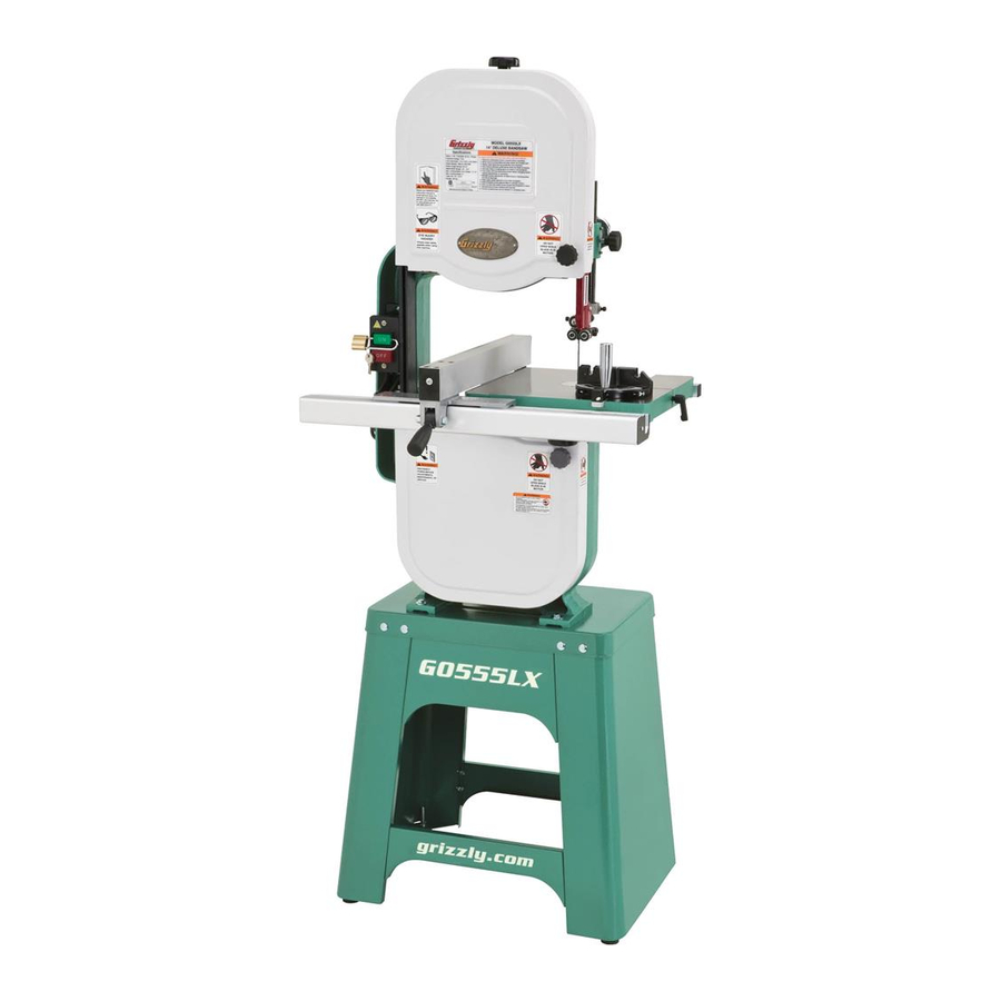
MODEL G0555LX
14" DELUXE BANDSAW
OWNER'S MANUAL
(For models manufactured since 1/14)
177335
COPYRIGHT © FEBRUARY, 2012 BY GRIZZLY INDUSTRIAL, INC., REVISED AUGUST, 2022 (MN)
WARNING: NO PORTION OF THIS MANUAL MAY BE REPRODUCED IN ANY SHAPE
OR FORM WITHOUT THE WRITTEN APPROVAL OF GRIZZLY INDUSTRIAL, INC.
#KN14662 PRINTED IN TAIWAN
V3.08.22
***Keep for Future Reference***
Advertisement
Table of Contents

Related Manuals for Grizzly G0555LX


Summary of Contents for Grizzly G0555LX
- Page 1 (For models manufactured since 1/14) 177335 COPYRIGHT © FEBRUARY, 2012 BY GRIZZLY INDUSTRIAL, INC., REVISED AUGUST, 2022 (MN) WARNING: NO PORTION OF THIS MANUAL MAY BE REPRODUCED IN ANY SHAPE OR FORM WITHOUT THE WRITTEN APPROVAL OF GRIZZLY INDUSTRIAL, INC.
- Page 2 This manual provides critical safety instructions on the proper setup, operation, maintenance, and service of this machine/tool. Save this document, refer to it often, and use it to instruct other operators. Failure to read, understand and follow the instructions in this manual may result in fire or serious personal injury—including amputation, electrocution, or death.
-
Page 3: Table Of Contents
Table of Contents INTRODUCTION ..........2 SECTION 5: ACCESSORIES ......43 Contact Info............ 2 SECTION 6: MAINTENANCE ......44 Manual Accuracy ........... 2 Schedule ............44 Identification ........... 3 Lubrication ........... 44 Machine Data Sheet ........4 Cleaning & Protecting ........44 SECTION 1: SAFETY ........ -
Page 4: Introduction
Always consider safety first, as it applies to your individual working conditions. Use this and other machinery with caution and respect. Failure to do so could result in serious personal injury, damage to equip- ment, or poor work results. Model G0555LX (Mfd. Since 1/14) -
Page 5: Identification
Do not remove jammed cutoff pieces until blade has stopped. Maintain proper adjustment of blade tension, blade guides, and thrust bearings. d) Adjust upper guide to just clear workpiece. Hold workpiece firmly against table. Model G0555LX (Mfd. Since 1/14) -
Page 6: Machine Data Sheet
MACHINE DATA SHEET Customer Service #: (570) 546-9663 · To Order Call: (800) 523-4777 · Fax #: (800) 438-5901 MODEL G0555LX 14" 1 HP DELUXE BANDSAW Product Dimensions: Weight................................229 lbs. Width (side-to-side) x Depth (front-to-back) x Height..............27 x 30 x 67-1/2 in. - Page 7 The information contained herein is deemed accurate as of 8/16/2022 and represents our most recent product specifications. Model G0555LX PAGE 2 OF 3 Due to our ongoing improvement efforts, this information may not accurately describe items previously purchased. Model G0555LX (Mfd. Since 1/14)
-
Page 8: Section 1: Safety
Never operate under the influence of drugs or injury or blindness from flying particles. Everyday alcohol, when tired, or when distracted. eyeglasses are NOT approved safety glasses. Model G0555LX (Mfd. Since 1/14) - Page 9 EXPERIENCING DIFFICULTIES. If at any time debris. Make sure they are properly installed, you experience difficulties performing the intend- undamaged, and working correctly BEFORE ed operation, stop using the machine! Contact our operating machine. Technical Support at (570) 546-9663. Model G0555LX (Mfd. Since 1/14)
-
Page 10: Additional Safety For Bandsaws
DO NOT try to stop or slow blade with your This machine is NOT designed to cut metal, hand or the workpiece. glass, stone, tile, etc. Model G0555LX (Mfd. Since 1/14) -
Page 11: Section 2: Power Supply
Nominal Voltage ..208V, 220V, 230V, 240V meets the specified circuit requirements. Cycle ............60 Hz Phase ........... Single-Phase Power Supply Circuit ......15 Amps Plug/Receptacle ......NEMA 6-15 Model G0555LX (Mfd. Since 1/14) - Page 12 The plug must only be inserted into a matching receptacle (see following figure) that is properly installed and grounded in accordance with all local codes and ordinances. -10- Model G0555LX (Mfd. Since 1/14)
-
Page 13: Converting Voltage To 220V
Remove the 5-15 plug from the cord. Tighten all wire nuts and secure them with electrical tape so they cannot vibrate loose during motor operation. Install the 6-15 plug on the power cord per the plug manufacturer's instructions. -11- Model G0555LX (Mfd. Since 1/14) -
Page 14: Section 3: Setup
IMPORTANT: Save all packaging materials until you are completely satisfied with the machine and have resolved any issues between Grizzly or the shipping agent. You MUST have the original pack- aging to file a freight claim. It is also extremely helpful if you need to return your machine later. -
Page 15: Inventory
—Eccentrics ⁄ " .......... 2 packaging materials. Often, these items get —Quick-Release Lever ......1 lost in packaging materials while unpack- ing or they are pre-installed at the factory. -13- Model G0555LX (Mfd. Since 1/14) -
Page 16: Hardware Recognition Chart
Hardware Recognition Chart USE THIS CHART TO MATCH UP HARDWARE DURING THE INVENTORY AND ASSEMBLY PROCESS. Flat Head Screw -14- Model G0555LX (Mfd. Since 1/14) -
Page 17: Cleanup
Figure 6. T23692 Orange Power Degreaser. Repeat Steps 2–3 as necessary until clean, then coat all unpainted surfaces with a quality metal protectant to prevent rust. -15- Model G0555LX (Mfd. Since 1/14) -
Page 18: Site Considerations
Only install in an Shadows, glare, or strobe effects that may distract access restricted location. or impede the operator must be eliminated. 30" 27" Figure 7. Minimum working clearances. -16- Model G0555LX (Mfd. Since 1/14) -
Page 19: Anchoring To Floor
Stand Side Flat Washer Figure 9. Upper and lower stand braces Machine Base attached to the stand side. Lag Shield Anchor Concrete Drilled Hole Figure 8. Popular method for anchoring machinery to a concrete floor. -17- Model G0555LX (Mfd. Since 1/14) - Page 20 Foot Hex Nut Flat Washer Flat Washer Hex Nut Figure 11. Stand foot installed (1 of 4). Figure 13. Leveling the stand. -18- Model G0555LX (Mfd. Since 1/14)
- Page 21 Figure 15, and secure it with (2) ⁄ "-18 x 1 ⁄ " hex bolts and ⁄ " lock washers. Trunnion Figure 17. Installing rear fence rail. Figure 15. Trunnion installed (table removed for clarity). -19- Model G0555LX (Mfd. Since 1/14)
- Page 22 19), and lower the fence onto the front fence Upper rail, as shown in Figure 20. Clutch Quick-Release Lever Rail Pad Figure 21. Quick-release lever installed. L-Brace Rear Fence Rail Figure 19. L-Brace positioned over rear fence rail. -20- Model G0555LX (Mfd. Since 1/14)
-
Page 23: Adjustment Overview
Below is an overview of all the adjustments and the order in which they should be performed: Bandsaw wheels are either flat or crowned and both shapes track differently. The G0555LX has Blade Tracking crowned wheels. As the wheels spin the blade... - Page 24 ⁄ ". The wheels on the G0555LX were aligned at the factory, so center tracking is the only adjustment Open the upper wheel cover. that needs to be performed when the saw is new.
-
Page 25: Dust Collection
11. Close and secure the upper wheel cover before operating the bandsaw. Figure 26. 4" dust hose attached to dust port. Tug the hose to make sure it does not come off. Note: A tight fit is necessary for proper performance. -23- Model G0555LX (Mfd. Since 1/14) -
Page 26: Test Run
Machine should NOT start. If it does start, may result in malfunction or unexpect- the switch disabling feature is not functioning ed results that can lead to serious injury, properly and the switch must be replaced. death, or machine/property damage. -24- Model G0555LX (Mfd. Since 1/14) -
Page 27: Tensioning Blade
DISCONNECT MACHINE FROM POWER. Adjusting Blade Support Bearings and Adjusting Blade Guide Bearings on Make sure the blade is properly center track- Pages 26– 27. ing as instructed in the Blade Tracking on Page 21. -25- Model G0555LX (Mfd. Since 1/14) -
Page 28: Adjusting Blade Support Bearings
Figure 28. Upper support bearing assembly and controls. When using different size blades, the blade tensioning system may need to be reset for correct operation. Refer to Blade Tensioner on Page 54 for detailed instructions. -26- Model G0555LX (Mfd. Since 1/14) -
Page 29: Adjusting Blade Guide Bearings
(1 of 2) Figure 31. Blade guide bearing controls. Figure 30. Blade should be aligned approxi- mately 0.016" away from the bearing edge. Tighten the cap screw to lock the support bearing in place. -27- Model G0555LX (Mfd. Since 1/14) - Page 30 The support bearing must be set to prevent this. Whenever changing a blade or adjusting the blade tension or tracking, the support and guide bearings must be re-adjusted before resuming operation to ensure proper blade support. -28- Model G0555LX (Mfd. Since 1/14)
- Page 31 Loosen the jam nut that locks the positive stop bolt in place. Figure 36. Location of the table tilt scale. Loosen the Phillips head screw securing the pointer, adjust the pointer to 0°, then retighten the Phillips head screw. -29- Model G0555LX (Mfd. Since 1/14)
-
Page 32: Aligning Table
Verify the setting and, if necessary, repeat this procedure until you are satisfied with the adjustment. Figure 37. Placing a straightedge along the blade and measuring to the miter slot. -30- Model G0555LX (Mfd. Since 1/14) -
Page 33: Aligning Fence
Figure 39. Location of the fence adjustment cap flush and evenly against both miter gauge screws. face and blade side. Loosen screw that secures angle pointer, adjust pointer to 0˚ mark on scale, then retighten screw to secure setting. -31- Model G0555LX (Mfd. Since 1/14) -
Page 34: Section 4: Operations
Read books/magazines or get formal training before beginning any proj- ects. Regardless of the content in this sec- tion, Grizzly Industrial will not be held liable for accidents caused by lack of training. -32- Model G0555LX (Mfd. Since 1/14) -
Page 35: Disabling & Locking Switch
With cuts. any padlock used to lock the switch, test the switch after installation to ensure that it is properly disabled. 0.192"–0.2" -33- Model G0555LX (Mfd. Since 1/14) -
Page 36: Workpiece Inspection
Minor Warping: Workpieces with slight cup- ping can be safely supported if the cupped side is facing the table or the fence. A workpiece supported on the bowed side may move unexpectedly resulting in severe injury. -34- Model G0555LX (Mfd. Since 1/14) -
Page 37: Blade Speed
Table Tilt Blade Speed The table can be tilted to make angled or beveled The Model G0555LX offers blade speeds of 1800 cuts. A simple tilt scale is provided on the trun- and 3100 FPM. Speed changes are made by re- nion for a quick gauge (see Figure 43). -
Page 38: Blade Information
Motor Wheel Figure 46. ⁄ " V-belt deflection. Close the lower wheel cover before re-con- necting the bandsaw to power. Cutting Radius Figure 47. Recommended cutting radius per blade width. -36- Model G0555LX (Mfd. Since 1/14) - Page 39 Hook: The teeth have a positive angle (down- ward) which makes them dig into the material, and the gullets are usually rounded for easier waste removal. These blades are excellent for the tough demands of resawing and rip- ping thick material. -37- Model G0555LX (Mfd. Since 1/14)
-
Page 40: Changing Blade
Figure 50. Changing the blade. To change blade: DISCONNECT MACHINE FROM POWER! Move the blade tension quick release lever to the left to release blade tension. -38- Model G0555LX (Mfd. Since 1/14) -
Page 41: Eccentrics
Eccentrics slide it through the table slot. Note: If the teeth will not point downward in any orientation, the blade is inside out. The model G0555LX comes with ⁄ " eccentrics Remove the blade and twist it right-side out. (PN P0555LX129) installed behind the guide bearings. -
Page 42: Ripping
NEVER place fingers or hands in the line of cut. If you slip, your hands or fingers may go into the blade and may be cut. -40- Model G0555LX (Mfd. Since 1/14) -
Page 43: Crosscutting
Always use push blocks when resawing and keep your hands clear of the blade. Figure 53. Example of a crosscutting operation with the miter gauge. -41- Model G0555LX (Mfd. Since 1/14) -
Page 44: Cutting Curves
Figure 55 for an example of a stacked cut ⁄ '' ..........1 ⁄ setup). ⁄ '' ..........2 ⁄ ⁄ '' ..........3 ⁄ ⁄ '' ..........5 ⁄ Figure 55. Example of a stacked cut setup. -42- Model G0555LX (Mfd. Since 1/14) -
Page 45: Section 5: Accessories
This Riser Block Kit increases the maximum cut- G5161 ⁄ " ⁄ " 18 Raker 0.025 ting height of the G0555LX 14" bandsaw from 6" G5162 ⁄ " ⁄ " 4 Hook 0.025 to 12". The T25555 has the green color scheme G5163 ⁄... -
Page 46: Section 6: Maintenance
Figure 58. Recommended products for protect- If the table becomes difficult to tilt, remove it and ing unpainted cast iron/steel part on machinery. lubricate the trunnions and the slides in the trun- nion base. -44- Model G0555LX (Mfd. Since 1/14) -
Page 47: Section 7: Service
11. Move machine closer to power supply; use shorter extension cord. 12. Centrifugal switch/contact points at fault. 12. Adjust centrifugal switch/clean contact points. Replace either if at fault. 13. Motor or motor bearings at fault. 13. Replace motor. -45- Model G0555LX (Mfd. Since 1/14) - Page 48 3. Blade loose and fluttering. 3. Increase blade tension as required (Page 25). scoring. 4. Adjust blade tracking (Page 21). 4. Blade tracking incorrect. 5. Blade has missing/bent teeth; faulty weld. 5. Replace blade (Page 38). -46- Model G0555LX (Mfd. Since 1/14)
- Page 49 2. Repair ducting for leaks or clogs, move dust collector cabinet. system. closer to machine, install a stronger dust collector. Gullets loaded 1. Excessive feed rate/pressure. 1. Reduce feed rate/pressure. with chips. 2. Blade TPI is too fine. 2. Install correct blade. -47- Model G0555LX (Mfd. Since 1/14)
-
Page 50: Checking/Tensioning V-Belt
⁄ " deflection in the V-belt. Pulley Re-tighten both cap screws and close the Approximately ⁄ " wheel cover. Deflection Pulley Figure 59. Checking the V-belt tension. -48- Model G0555LX (Mfd. Since 1/14) -
Page 51: Replacing V-Belt
Follow the procedures in Aligning Table on Page release the V-belt tension. 30 to ensure accurate cutting. Roll the V-belt off the pulleys. Remove the wheel mount (it has left hand threads, so it loosens by turning clockwise). -49- Model G0555LX (Mfd. Since 1/14) -
Page 52: Wheel Alignment
Adjust blade tracking knob to the rear adjustment set tilt the top wheel. screws to tilt the top wheel left/right. Figure 64. Wheel alignment illustration. Figure 63. Checking if the wheels are coplanar. -50- Model G0555LX (Mfd. Since 1/14) - Page 53 Remove the wheel to be shimmed. Place as machine. many shims as necessary to correct the gap measured in Step 3 onto the wheel shaft. Re-install the wheel and secure it in place. Re-install the blade and properly tension it. -51- Model G0555LX (Mfd. Since 1/14)
-
Page 54: Blade Lead
Straightedge the following procedures. Figure 68. Before and after lateral wheel alignment (viewed from above). Re-tighten the hex nuts loosened in Step 6. -52- Model G0555LX (Mfd. Since 1/14) -
Page 55: Fence Scale Calibration
Repeat Steps 1–5 until there is no longer any Figure 70. Fence scale window and screws. blade lead. Re-tighten the screws—the scale is now cor- rectly calibrated. -53- Model G0555LX (Mfd. Since 1/14) -
Page 56: Blade Tensioner
Using two 14mm wrenches, loosen the lower jam nuts and thread them up the shaft. Using the two 14mm wrenches, loosen the upper jam nuts and thread them up the shaft the same distance as the lower jam nuts. -54- Model G0555LX (Mfd. Since 1/14) -
Page 57: Section 8: Wiring
Technical Support at (570) 546-9663. The photos and diagrams included in this section are best viewed in color. You can view these pages in color at www.grizzly.com. -55- Model G0555LX (Mfd. Since 1/14) -
Page 58: Wiring Diagram (110V)
Motor at 110V-120V (prewired) Start Capacitor Motor Start 300MFD 125VAC 110V Capacitor Capacitor 200 MFD 30 MFD 125 VAC 250 VAC 3 RED 2 GRAY 1 BLACK 4 YELLOW Ground Ground READ ELECTRICAL SAFETY -56- G0555LX (Mfd. Since 1/14) ON PAGE 55! -
Page 59: Wiring Diagram (220V)
Motor at 110V-120V (prewired) Start Capacitor Capacitor 200 MFD 30 MFD 125 VAC Motor 250 VAC Start Capacitor 300MFD 125VAC 220V 3 RED 2 GRAY 4 YELLOW 1 BLACK Ground Ground READ ELECTRICAL SAFETY -57- G0555LX (Mfd. Since 1/14) ON PAGE 55! -
Page 60: Electrical Photos
Electrical Photos Figure 73. Motor wiring. Figure 72. ON/OFF switch wiring. Figure 74. Start capacitor wiring. READ ELECTRICAL SAFETY -58- G0555LX (Mfd. Since 1/14) ON PAGE 55! -
Page 61: Section 9: Parts
SECTION 9: PARTS We do our best to stock replacement parts when possible, but we cannot guarantee that all parts shown are available for purchase. Call (800) 523-4777 or visit www.grizzly.com/parts to check for availability. Main 34V2 14-2 14-3 49 50... - Page 62 INDICATOR NUT 3/8 X 16 P0555LX095 HEX BOLT 1/4-20 X 3/4 P0555LX040 UPPER WHEEL P0555LX096 CAP SCREW 10-32 X 1/4 P0555LX041 WHEEL TIRE BUY PARTS ONLINE AT GRIZZLY.COM! -60- Model G0555LX (Mfd. Since 1/14) Scan QR code to visit our Parts Store.
- Page 63 ROLL PIN 4 X 30 P0555LX134 PLASTIC HANDLE 3/8-16 P0555LX212 FLAT WASHER 3/8 P0555LX135 UPPER CLUTCH P0555LX214 LOWER CLUTCH P0555LX138 HEX BOLT 5/16-18 X 1-1/4 BUY PARTS ONLINE AT GRIZZLY.COM! -61- Model G0555LX (Mfd. Since 1/14) Scan QR code to visit our Parts Store.
- Page 64 Table, Fence & Stand 114-5 114-8 114-9 114-14 114-1 114-13 114-6 114-3 114-2 114-10 114-7 114-4 114-12 BUY PARTS ONLINE AT GRIZZLY.COM! -62- Model G0555LX (Mfd. Since 1/14) Scan QR code to visit our Parts Store.
- Page 65 WRENCH 10 X 12MM OPEN-ENDS 114-7 P0555LX114-7 STUD-SE 1/4-20 X 1-1/8, 1/2 P0555LX227 HEX WRENCH 5MM 114-8 P0555LX114-8 FLAT WASHER 1/4 PL BUY PARTS ONLINE AT GRIZZLY.COM! -63- Model G0555LX (Mfd. Since 1/14) Scan QR code to visit our Parts Store.
-
Page 66: Labels & Cosmetics
DO NOT REPRODUCE OR CHANGE THIS ARTWORK oil-resistant material Generic Labels service. using this machine. WITHOUT WRITTEN APPROVAL! Grizzly will not accept labels changed without approval. • Labels must be made of (7/23/13) artwork changes are required, contact us immediately at manuals@grizzly.com. oil-resistant material... -
Page 67: Warranty & Returns
WARRANTY & RETURNS Grizzly Industrial, Inc. warrants every product it sells for a period of 1 year to the original purchaser from the date of purchase. This warranty does not apply to defects due directly or indirectly to misuse, abuse, negligence, accidents, repairs or alterations or lack of maintenance.