Table of Contents
Advertisement
Quick Links
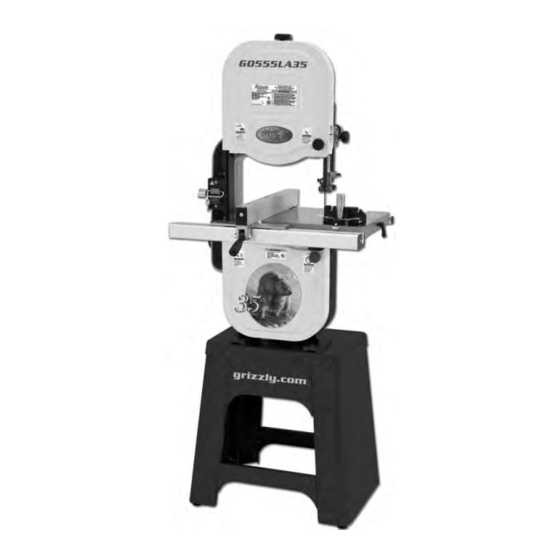
MODEL G0555LA35
14" DELUXE BANDSAW
ANNIVERSARY EDITION
MANUAL INSERT
The Model G0555LA35 is the same machine as the Model G0555LX except for the 35-Year Anniversary
design. Except for the differences noted in this insert, all other content in the Model G0555LX owner's
manual applies to this machine. Before operating your new machine, you MUST read and understand this
insert and the entire Model G0555LX manual to reduce the risk of injury when using this machine.
If you have any further questions about this manual insert or your machine, contact our Technical Support
at (570) 546-9663 or email techsupport@grizzly.com.
177335
COPYRIGHT © FEBRUARY, 2013 BY GRIZZLY INDUSTRIAL, INC., REVISED FEBRUARY, 2018 (MN)
WARNING: NO PORTION OF THIS MANUAL MAY BE REPRODUCED IN ANY SHAPE
OR FORM WITHOUT THE WRITTEN APPROVAL OF GRIZZLY INDUSTRIAL, INC.
FOR MODELS MANUFACTURED SINCE 11/17 #TS15614 PRINTED IN TAIWAN
Advertisement
Table of Contents

Related Manuals for Grizzly G0555LA35


Summary of Contents for Grizzly G0555LA35
- Page 1 ANNIVERSARY EDITION MANUAL INSERT The Model G0555LA35 is the same machine as the Model G0555LX except for the 35-Year Anniversary design. Except for the differences noted in this insert, all other content in the Model G0555LX owner's manual applies to this machine. Before operating your new machine, you MUST read and understand this insert and the entire Model G0555LX manual to reduce the risk of injury when using this machine.
- Page 2 MACHINE DATA SHEET Customer Service #: (570) 546-9663 · To Order Call: (800) 523-4777 · Fax #: (800) 438-5901 MODEL G0555LA35 14" DELUXE BANDSAW ‐ 35TH ANNIVERSARY EDITION Product Dimensions: Weight................................229 lbs. Width (side-to-side) x Depth (front-to-back) x Height..............27 x 30 x 67-1/2 in.
- Page 3 The information contained herein is deemed accurate as of 2/7/2018 and represents our most recent product specifications. Model G0555LA35 PAGE 2 OF 2 Due to our ongoing improvement efforts, this information may not accurately describe items previously purchased. Model G0555LA35 (Mfd. Since 11/17)
- Page 4 ⁄ " eccentrics. Retighten cap screw on guide shaft bracket, then re-install guide bearings and guide- Introduction bearing cap screws. The model G0555LX and G0555LA35 bandsaws come with ⁄ " eccentrics (Part # P0555LA35129) Install ⁄ " blade as described in owner's installed behind the guide bearings.
- Page 5 Installing unapproved accessories may cause machine to malfunction, resulting in serious personal injury or machine damage. To reduce this risk, only install accessories recommended for this machine by Grizzly. NOTICE Refer to our website or latest catalog for additional recommended accessories.
- Page 6 Please Note: We do our best to stock replacement parts whenever possible, but we cannot guarantee that all parts shown here are available for purchase. Call (800) 523-4777 or visit our online parts store at www.grizzly.com to check for availability.
- Page 7 INDICATOR NUT 3/8 X 16 P0555LA35095 HEX BOLT 1/4-20 X 3/4 P0555LA35040 UPPER WHEEL P0555LA35096 CAP SCREW 10-32 X 1/4 P0555LA35041 WHEEL TIRE BUY PARTS ONLINE AT GRIZZLY.COM! Model G0555LA35 (Mfd. Since 11/17) Scan QR code to visit our Parts Store.
- Page 8 P0555LA35193 KNOB BOLT 5/16-18 X 2 P0555LA35131 HEX NUT 3/8-16 P0555LA35194 SHAFT BRACKET P0555LA35133 STUD-UDE 3/8-16 X 10 1, 3/4 P0555LA35195 ROLL PIN 4 X 30 P0555LA35134 PLASTIC HANDLE 3/8-16 P0555LA35212 FLAT WASHER 3/8 P0555LA35135 UPPER CLUTCH P0555LA35214 LOWER CLUTCH Model G0555LA35 (Mfd. Since 11/17)
- Page 9 Table, Fence, & Stand Parts 192 153 114-5 114-8 114-9 114-14 114-1 114-13 114-6 114-3 114-2 114-10 114-7 114-4 114-12 Model G0555LA35 (Mfd. Since 11/17)
- Page 10 STOP DOWEL P0555LA35213 STAND FOOT 3/8-16 X 2 P0555LA35226 WRENCH 10 X 12MM OPEN-ENDS 114-5 P0555LA35114-5 MITER HANDLE 1/4-20 P0555LA35227 HEX WRENCH 5MM 114-6 P0555LA35114-6 SCALE PLATE 114-7 P0555LA35114-7 STUD-SE 1/4-20 X 1-1/8, 1/2 -10- Model G0555LA35 (Mfd. Since 11/17)
- Page 11 Safety labels help reduce the risk of serious injury caused by machine hazards. If any label comes off or becomes unreadable, the owner of this machine MUST replace it in the original location before resuming operations. For replacements, contact (800) 523-4777 or www.grizzly.com. -11-...
- Page 12 -12- Model G0555LA35 (Mfd. Since 11/17)
- Page 13 (For models manufactured since 3/13) 177335 COPYRIGHT © FEBRUARY, 2012 BY GRIZZLY INDUSTRIAL, INC., REVISED APRIL, 2013 (TS) WARNING: NO PORTION OF THIS MANUAL MAY BE REPRODUCED IN ANY SHAPE OR FORM WITHOUT THE WRITTEN APPROVAL OF GRIZZLY INDUSTRIAL, INC.
- Page 14 This manual provides critical safety instructions on the proper setup, operation, maintenance, and service of this machine/tool. Save this document, refer to it often, and use it to instruct other operators. Failure to read, understand and follow the instructions in this manual may result in fire or serious personal injury—including amputation, electrocution, or death.
-
Page 15: Table Of Contents
Table of Contents INTRODUCTION ..........2 Blade Speed ..........33 Manual Accuracy ........... 2 Blade Information ......... 34 Contact Info............ 2 Blade Dimensions ........34 Machine Description ........2 Changing Blade ........... 36 Identification ........... 3 Ripping ............37 Machine Data Sheet ........4 Crosscutting .......... -
Page 16: Introduction
Any updates to your model and table. of machine will be reflected in these documents as soon as they are complete. -
Page 17: Identification
Identification Blade Quick Blade Tension Knob Release Lever Upper Wheel Blade Tracking Guide Post Guard Knob Blade Tension Control Knob Scale Guide Post Upper Blade Control Knob Switch Guide Assembly Miter Gauge Fence Fence Lock Handle Table Pin Table Tilt Table Insert Lock Knob Lower Wheel... -
Page 18: Machine Data Sheet
Machine Data Sheet MACHINE DATA SHEET Customer Service #: (570) 546-9663 · To Order Call: (800) 523-4777 · Fax #: (800) 438-5901 MODEL G0555LX 14" DELUXE BANDSAW Product Dimensions: Weight................................229 lbs. Width (side-to-side) x Depth (front-to-back) x Height..............27 x 30 x 67-1/2 in. Footprint (Length x Width)....................... - Page 19 Blade Information Standard Blade Length........................93-1/2 in. Blade Length Range......................92-1/2 – 93-1/2 in. Blade Width Range.......................... 1/8 – 3/4 in. Type of Blade Guides........................Ball Bearing Guide Post Adjustment Type........................Manual Has Quick-Release............................Yes Table Information Table Length.............................. 14 in. Table Width..............................
-
Page 20: Section 1: Safety
SECTION 1: SAFETY For Your Own Safety, Read Instruction Manual Before Operating This Machine The purpose of safety symbols is to attract your attention to possible hazardous conditions. This manual uses a series of symbols and signal words intended to convey the level of impor- tance of the safety messages. - Page 21 INTENdEd usAGE. Only use machine for its machine in good working condition. A machine intendedpurposeandnevermakemodifications that is improperly maintained could malfunction, not approved by Grizzly. Modifying machine or leadingtoseriouspersonalinjuryordeath. using it differently than intended may result in ChECK dAMAGEd PARTs. Regularly inspect...
-
Page 22: Additional Safety For Bandsaws
Additional Safety for Bandsaws BLADE CONDITION. Do not operate with dull, CUTTING TECHNIQUES. Plan your cuts so you cracked or badly worn blade. Dull blades require always cut out of the wood. DO NOT back the more effort to perform the cut. Inspect blades for workpiece away from the blade while the saw is cracks and missing teeth before each use. -
Page 23: Section 2: Power Supply
SECTION 2: POWER SUPPLY Availability Circuit Information Before installing the machine, consider the avail- A power supply circuit includes all electrical ability and proximity of the required power supply equipment between the breaker box or fuse panel circuit. If an existing circuit does not meet the in the building and the machine. -
Page 24: Grounding Requirements
Grounding Requirements This machine MUST be grounded. In the event of certain malfunctions or breakdowns, grounding reduces the risk of electric shock by providing a path of least resistance for electric current. Improper connection of the equipment-grounding wire can result in a risk of electric shock. The wire with green insulation (with or without yellow SHOCK HAZARD! stripes) is the equipment-grounding wire. -
Page 25: Extension Cords
Extension Cords To convert the machine to 220V: We do not recommend using an extension cord DISCONNECT MACHINE FROM POWER! with this machine. If you must use an extension cord, only use it if absolutely necessary and only Remove the 5-15 plug from the cord. on a temporary basis. -
Page 26: Section 3: Set Up
SECTION 3: SET UP Set Up Safety Needed for Setup The following are needed to complete the setup process, but are not included with your machine. This machine presents serious injury hazards Description to untrained users. Read • Additional People ....... As Needed through this entire manu- •... -
Page 27: Inventory
Inventory The following is a list of items shipped with your machine. Before beginning setup, lay these items out and inventory them. If any non-proprietary parts are missing (e.g. a nut or a washer), we will gladly replace them; or for the sake of expediency, replacements can be obtained at your local hardware store. -
Page 28: Cleanup
Cleanup Gasoline or products with low flash points can The unpainted surfaces of your machine are explode or cause fire if coated with a heavy-duty rust preventative that used to clean machin- prevents corrosion during shipment and storage. ery. Avoid cleaning with This rust preventative works extremely well, but it these products. -
Page 29: Site Considerations
Site Considerations Weight Load Physical Environment Refer to the Machine Data Sheet for the weight The physical environment where the machine is of your machine. Make sure that the surface upon operated is important for safe operation and lon- which the machine is placed will bear the weight gevity of machine components. -
Page 30: Assembly
Assembly Attach the remaining stand side to the assem- bly, as shown in Figure 9, with (8) ⁄ "-20 x ⁄ " hex bolts, (8) ⁄ " flat washers, and (8) ⁄ "-20 flange nuts. Some sheet metal parts may have sharp edges that can cause minor cuts. - Page 31 Turn the stand assembly upright and attach With the help of other people, lift the bandsaw the top, as shown in Figure 11, with (8) ⁄ "- assembly onto the stand and align the mount- 18 x ⁄ " carriage bolts and (8) ⁄...
- Page 32 10. Line up the table slot with the blade, then 14. Attach the front fence rail shown in Figure 17, position the table so that the blade is in the with (2) ⁄ "-20 x ⁄ " hex bolts and ⁄...
-
Page 33: Adjustment Overview
Adjustment 16. Thread the M6-1 hex nut onto the fence rail pad, then thread it into the rear underside of Overview the fence (see Figure 19) so that the fence rests the same height above the table along its full length. Tighten the hex nut against the fence to secure the setting. -
Page 34: Blade Tracking
Blade Tracking "Tracking" refers to how the blade rides on the bandsaw wheels. Proper tracking is important for maintaining bandsaw adjustments, achiev- ing correct blade tension, and cutting accurate- ly. Improper tracking reduces cutting accuracy, causes excess vibrations, and places stress on the blade and other bandsaw components. - Page 35 To center track the blade: — If the blade rides in the center of the upper wheel and is centered on the peak of the DISCONNECT BANDSAW FROM POWER! wheel crown, it is properly tracking and you are done with this procedure—proceed to Adjust the upper and lower blade guides Dust Collection on Page 22.
-
Page 36: Dust Collection
Dust Collection Dust Collection Power Connection After you have completed all previous setup instructions and circuit requirements, the machine is ready to be connected to the power supply. DO NOT operate this bandsaw without an ade- quate dust collection system. This bandsaw To avoid unexpected startups or property dam- creates substantial amounts of wood dust age, use the following steps whenever connecting... -
Page 37: Test Run
Test Run Padlock Shaft Once the assembly is complete, test run your machine to make sure it runs properly and is ready for regular operation. The test run consists of verifying the following: 1) The motor powers up and runs correctly, and 2) the safety disabling mechanism on the switch Figure 28. -
Page 38: The Flutter Method
The Deflection Method Note: Tensioning the blade according to the blade tension scale before the Test Run was an The deflection method is much more subjective approximate tension. The following procedures than the flutter method. Each blade will deflect fine-tunes the blade tension. differently and every user will determine what "moderate pressure"... -
Page 39: Adjusting Blade Support Bearings
Adjusting Blade Loosen the guide assembly lock bolt so that the support bearing can be rotated perpen- Support Bearings dicular to the blade in the next step. Rotate the blade guide assembly until the face of the support bearing is perpendicular The support bearings are positioned behind the to the blade, as illustrated in the Figure 30. -
Page 40: Adjusting Blade Guide Bearings
Tip: To quickly gauge this setting, fold a crisp Familiarize yourself with the blade guide con- trols shown in Figure 33. dollar bill in half twice (when folded tightly, four thicknesses of a dollar bill is approxi- mately 0.016"). Place the folded dollar bill between the support bearing and the blade, Guide Bearing as shown in Figure 32. - Page 41 Table Tilt Calibration Loosen both cap screws behind the guide bearings, then rotate the adjustment cap screws so the bearings evenly and lightly touch the sides of the blade (see the illustra- When properly adjusted, the positive stop bolt tion in Figure 35) without deflecting it one enables the table to be quickly returned perpen- way or the other.
-
Page 42: Aligning Table
Aligning Table Completely raise the upper blade guide assembly, then place the machinist's square flat on the table and against the side of the blade, as illustrated in Figure 37. To ensure cutting accuracy, the table must be aligned so the miter slot is parallel with the bandsaw blade. -
Page 43: Aligning Fence
Aligning Fence Use the fine ruler to measure the distance between the straightedge and miter slot at the front and back of the table (see Figure 39). To ensure accurate cutting when using the fence, — If the distances are the same, no further the face of the fence must be parallel to the table adjustments are required. -
Page 44: Section 4: Operations
OMMEND that you read books, review industry trade magazines, or get formal training before beginning any projects. Regardless of the content in this section, Grizzly Industrial will not be held liable for accidents caused by lack of training. -30- G0555LX (Mfg. Since 3/13) -
Page 45: Straight Cuts
Disabling & Locking The bandsaw is one of the most versatile wood cutting tools in the shop. It is capable of perform- Switch ing the following types of cuts: Straight Cuts The ON/OFF switch can be disabled and locked • Miters by inserting a padlock through the ON button, •... -
Page 46: Workpiece Inspection
Workpiece Guide Post Inspection The guide post, shown in Figure 43, allows the upper blade guide assembly to be quickly adjust- Some workpieces are not safe to cut or may ed for height. When cutting, the blade guides require modification before they are safe to cut. must always be positioned so they just clear (no Before cutting, inspect all workpieces for the more than... -
Page 47: Blade Speed
Table Tilt Blade Speed The table can be tilted to make angled or beveled The Model G0555LX offers blade speeds of 1800 cuts. A simple tilt scale is provided on the trun- and 3100 FPM. Speed changes are made by re- nion for a quick gauge (see Figure 44). -
Page 48: Blade Information
Refer to the Accessories section later in this manual for blade replace- Figure 46. Belt positions for different speeds. ments from Grizzly. Blade Width Pivot the motor so the upper cap screw slides Measured from the back of the blade to the tip of left in the slot. - Page 49 Tooth Pitch Straight Cutting: Use the largest width blade • that you own. Large blades excel at cutting Measured as TPI (teeth per inch), tooth pitch straight lines and are less prone to wander. determines the number of teeth. More teeth per inch (fine pitch) will cut slower, but smoother;...
-
Page 50: Changing Blade
The most common causes of blade breakage Remove the fence and miter gauge from the are: table, then remove the table insert and table pin (see Figure 50). • Faulty alignment/adjustment of the guides. • Forcing/twisting a wide blade around a short radius. -
Page 51: Ripping
Ripping Position the blade so that the teeth are facing to the right and down toward the table, then slide it through the table slot. "Ripping" means cutting with the grain of the Note: If the teeth will not point downward wood stock. -
Page 52: Crosscutting
Crosscutting Resawing "Resawing" means cutting the thickness of a board into two or more thinner boards (see Figure 54 for Crosscutting is the process of cutting across the an example). The maximum height of a board that grain of wood. For plywood and other processed can be resawn is limited by the maximum cutting wood, crosscutting simply means cutting across height of the bandsaw. -
Page 53: Cutting Curves
Cutting Curves Stacked Cuts One of the benefits of a bandsaw is its ability to When cutting curves, simultaneously feed and cut multiple copies of a particular shape by stack- turn the stock carefully so the blade follows the layout line without twisting. If curves are sharp or ing a number of workpieces together. -
Page 54: Section 5: Accessories
Grizzly. saving jigs and templates. 176 pages. NOTICE Refer to the newest copy of the Grizzly Catalog for other accessories available for this machine. Grizzly Bandsaw Blades Figure 56. Success with Bandsaws book. - Page 55 3 AS-S 0.025 H8526 ⁄ " ⁄ " 6 PC 0.032 Figure 59. H7587 Re-Saw Fence Retrofit Kit for H8527 ⁄ " ⁄ " 10 RK 0.032 the G0555LX Bandsaw. Order Online at grizzly.com ® -41- G0555LX (Mfg. Since 3/13)
- Page 56 H7195—Bifocal Safety Glasses 2.0 H7196—Bifocal Safety Glasses 2.5 T20502 T20452 T20503 Figure 63. Recommended lubricants for protect- ing unpainted cast iron/steel part on machinery. T20451 H7194 Figure 61. Assortment of basic eye protection. Order Online at grizzly.com ® -42- G0555LX (Mfg. Since 3/13)
-
Page 57: Section 6: Maintenance
SECTION 6: MAINTENANCE Lubricating Always disconnect power to the machine before Protect the unpainted cast iron surfaces on the performing maintenance. table by wiping the table clean after every use— Failure to do this may this ensures moisture from wood dust does not result in serious person- remain on bare metal surfaces. -
Page 58: Section 7: Service
SECTION 7: SERVICE Review the troubleshooting and procedures in this section if a problem develops with your machine. If you need replacement parts or additional help with a procedure, call our Technical Support at (570) 546-9663. Note: Please gather the serial number and manufacture date of your machine before calling. Troubleshooting Symptom Possible Cause... -
Page 59: Cutting Operations
Symptom Possible Cause Possible Solution Machine 1. Feeding workpiece too fast. 1. Reduce feed rate. slows when 2. Replace blade (Page 36). 2. Blade is dull. operating. 3. Workpiece moisture content is too high. 3. Replace workpiece. 4. Incorrect workpiece type. 4. -
Page 60: V-Belt Tension
V-Belt Tension Tensioning V-Belt Tool Needed Hex Wrench 6mm ..........1 To ensure optimum power transmission from the To properly tension the V-belt: motor to the blade, the V-belt must be in good condition and operate under proper tension. DISCONNECT BANDSAW FROM POWER! V-belt tension should be checked at least every Open the lower wheel cover, and loosen month—more often if the bandsaw is used daily. -
Page 61: Replacing V-Belt
Replacing V-Belt Remove the wheel from the shaft. Make sure not to misplace the shaft key. Put new belt on. To ensure optimum power transmission from the Align the wheel keyway with the shaft key, motor to the blade, the V-belt must be in good and slide the wheel back onto the shaft. -
Page 62: Wheel Alignment
Wheel Alignment Wheel alignment is important for optimal perfor- mance from your bandsaw. Wheels are properly aligned when they are parallel with each other and in the same plane or “coplanar” (see the illustra- tion in the figure to the right). When wheels are coplanar, the bandsaw is more likely to cut straight without wandering;... -
Page 63: Shimming A Wheel
Shimming a Wheel Perform the previous Checking Wheel Alignment procedure. If necessary to make A wheel that is parallel with the other wheel, but the wheels parallel, repeat this procedure. is not coplanar, must be shimmed by the distance that it is not in the same plane with the other Close the wheel covers. -
Page 64: Blade Lead
Blade Lead Using a white crayon or other light color marker, mark the upper and lower wheels to indicate the measuring locations, as illus- trated in Figure 72. Bandsaw blades may wander off the cut line when sawing, as shown in Figure 74. This is called blade lead. -
Page 65: Fence Scale Calibration
Fence Scale To skew your fence: Calibration Cut a piece of scrap wood approximately ⁄ " thick x 3" wide x 17" long. On the wide face of the board, draw a straight line parallel to the long edge. You may need to recalibrate the fence scale after changing or adjusting the blade, or if the scale Slide the bandsaw fence out of the way and is not producing accurate cuts. -
Page 66: Blade Tensioner
Blade Tensioner Using two 14mm wrenches, loosen the lower jam nuts and thread them up the shaft. Using the two 14mm wrenches, loosen the The blade tensioner may need to be reset for one upper jam nuts and thread them up the shaft of the following reasons: the same distance as the lower jam nuts. -
Page 67: Section 8: Wiring
Technical source. Support at (570) 546-9663. The photos and diagrams included in this section are best viewed in color. You can view these pages in color at www.grizzly.com. -53- G0555LX (Mfg. Since 3/13) -
Page 68: Electrical Locations
Electrical Locations Figure 77. G0555LX ON/OFF switch. Switch Motor READ ELECTRICAL SAFETY -54- G0555LX (Mfg. Since 3/13) ON PAGE 53! -
Page 69: Prewired) Wiring Diagram
(Switches Viewed from Behind) 110V (Prewired) Wiring Diagram Lamp Switch Start/Stop Switch Work Lamp Ground (40 Watt Maximum) 5-15 Plug Neutral 110-120 VAC Ground 110 VAC Neutral 5-15 Plug Ground (Pre-wired) Motor at 110V-120V (prewired) Start Capacitor Capacitor 200 MFD 30 MFD Start Capacitor 125 VAC... -
Page 70: Rewired) Wiring Diagram
(Switches Viewed from Behind) 220V (Rewired) Wiring Diagram Lamp Switch Start/Stop Switch Ground Work Lamp (40 Watt Maximum) Ground 5-15 Plug 110-120 VAC Ground Neutral 220 VAC 6-15 Plug (As Recommended) Motor at 110V-120V (prewired) Start Capacitor Capacitor 200 MFD 30 MFD 125 VAC 250 VAC... -
Page 71: Section 9: Parts
SECTION 9: PARTS Main 14-2 14-3 49 50 14-1 23 19 85 86 125 96 56 57 11-4 11-3 11-5 11-1 11-2 11-7 11-6 11-9 11-8 -57- G0555LX (Mfg. Since 3/13) - Page 72 Main Parts List REF PART # DESCRIPTION REF PART # DESCRIPTION P0555LX001 BASE PLN16 LOCK NUT 1/2-20 THIN PB64 HEX BOLT 5/8-11 X 2-1/2 PR21M INT RETAINING RING 35MM PW14 FLAT WASHER 5/8 P6202-2RS BALL BEARING 6202-2RS PN04 HEX NUT 5/8-11 P0555LX045 LOWER WHEEL P0555LX005...
- Page 73 Main Parts List (continued) PART # DESCRIPTION PART # DESCRIPTION PN02 HEX NUT 5/16-18 PLW01 LOCK WASHER 5/16 PB03 HEX BOLT 5/16-18 X 1 P0555LX140 CLUTCH SUPPORT BRACKET PLW01 LOCK WASHER 5/16 PLW04 LOCK WASHER 3/8 PW07 FLAT WASHER 5/16 PCAP06 CAP SCREW 1/4-20 X 1 P0555LX118...
- Page 74 Table, Fence, & Stand 114-5 114-8 114-9 114-14 114-1 114-13 114-6 114-3 114-2 114-10 114-7 114-4 114-12 -60- G0555LX (Mfg. Since 3/13)
- Page 75 Table, Fence & Guides Parts List PART # DESCRIPTION PART # DESCRIPTION PCAP43 CAP SCREW 1/4-20 X 2-1/2 114-7 P0555LX114-7 STUD-SE 1/4-20 X 1-1/8 PS28M PHLP HD SCR M8-1.25 X 30 114-8 P0555LX114-8 PLASTIC FLAT WASHER 1/4 P0555LX036 LOCK CAM 114-9 PW06 FLAT WASHER 1/4...
-
Page 76: Labels
Safety labels help reduce the risk of serious injury caused by machine hazards. If any label comes off or becomes unreadable, the owner of this machine MUST replace it in the original location before resuming operations. For replacements, contact (800) 523-4777 or www.grizzly.com. -62-... - Page 77 Would you recommend Grizzly Industrial to a friend? _____ Yes _____No Would you allow us to use your name as a reference for Grizzly customers in your area? Note: We never use names more than 3 times. _____ Yes _____No 10.
- Page 78 FOLD ALONG DOTTED LINE Place Stamp Here GRIZZLY INDUSTRIAL, INC. P.O. BOX 2069 BELLINGHAM, WA 98227-2069 FOLD ALONG DOTTED LINE Send a Grizzly Catalog to a friend: Name_______________________________ Street_______________________________ City______________State______Zip______ TAPE ALONG EDGES--PLEASE DO NOT STAPLE...
-
Page 79: Warranty And Returns
WARRANTY AND RETURNS Grizzly Industrial, Inc. warrants every product it sells for a period of 1 year to the original purchaser from the date of purchase. This warranty does not apply to defects due directly or indirectly to misuse, abuse, negligence, accidents, repairs or alterations or lack of maintenance.