Table of Contents
Advertisement
Quick Links
Advertisement
Table of Contents

Related Manuals for Rinnai 650FS


Summary of Contents for Rinnai 650FS
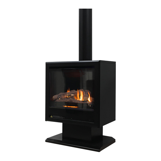
- Page 1 Model: 650FS 650 Free Standing Gas Fireplace Installation and Flueing Manual...
- Page 2 Congratulations on the purchase of your Rinnai 650FS Free Standing gas log flamefire. We trust you will have many years of comfort and enjoyment from your appliance. BEFORE USING THIS APPLIANCE Before proceeding with the operation or installation read this manual and the other manuals...
-
Page 3: Table Of Contents
Commissioning Instructions ............................18 Contacts This appliance MUST be installed, maintained and removed ONLY by an Authorised Person. For continued safety of this appliance it MUST be installed and maintained in accordance with WARNING the manufacturers instructions. Rinnai 650FS FIM... -
Page 4: Warnings & Important Information
Current AS/NZS 3500 & AS/NZS 5601. Local Regulations and Municipal Building Codes including local OH&S requirements. Your Rinnai 650FS gas fire and flue system has been certified by the Australian Gas Association. The A.G.A. Certification Number is shown on the data plate. -
Page 5: Modifications
Flue terminal MUST always vent directly to outdoors. DO NOT extend the flue vertically or horizontally in ways other than prescribed in this appliance manufacturer’s installation instructions. ONLY the flue components specified by Rinnai MUST be used. When considering installation ensure minimum clearances as follows are adhered to, refer Fig. 1. -
Page 6: Before You Start
BEFORE YOU START CARTON CONTENTS / ITEM CHECKLIST • The Engine, Fascia and Flue Adapter for the Rinnai 650FS Gas Fire is supplied in one carton. • The Flue is available as a kit, 650FSKIT01 and is supplied separately. •... -
Page 7: General Installation Information
Front Clearance - From front of glass to objects. 1000 Corner Installation Clearance - LH and RH rear corners at 45º to nearest surface. Flue clearance - Flue is cool to touch. Rinnai RDV 600_700ER IM... -
Page 8: Dimensions & Weights
GENERAL INSTALLATION INFORMATION DIMENSIONS & WEIGHTS Cabinet dimensions are as shown below. Refer to Rinnai 650 Installation and Operation manuals for full engine details. Gross Weight: 85 kg 650 FS - Overall Dimensions (+25 for flue spigot) All dimensions in mm... -
Page 9: Cabinet Installation
Locate and LOOSEN the 3 x M4 (7mm AF) hex head screws at the top of the discharge vent A. The fascia holes are slotted. Leave the screws loose in the panel. Locate and remove the screws at the bottom left and right of the inlet vent . Firmly draw fascia out and away and place carefully aside. Rinnai 650FS FIM... - Page 10 Engine is heavy. Two person lift required for this step. CAUTION Remove the 6 Phillips-head screws located at the left and right of the engine side panels. Carefully slide the engine forward and out of the cabinet. Gently place it down out of the way. Rinnai 650FS FIM...
- Page 11 Refer to adjacent image. IMPORTANT Refit top panel in reverse order of "Step 4. Remove top panel" on page 10. DO NOT re-attach fascia at this point. Proceed to installing the flue. Rinnai 650FS FIM...
-
Page 12: Flue Installation
FLUE INSTALLATION FLUE INSTALLATION OPTIONS These instructions ONLY apply to the Rinnai 650FS gas fire coaxial flueing system. This flue system utilises pipe components with an aluminium inner pipe, a white plastic outer pipe and powder coated dress pipe. WARNING Before commencing installation, please read the Installation Instructions located with the engine. -
Page 13: Flue Kit Components
650FSROOFCOWL B065413 650FS-PIPE1000-2 PLATE CEILING COVER B063960 13999020 PC TUBE O/A SWAGE X 2 SAPPHIRE 13999015 PC TUBE O/A SWAGE X 1 SAPPHIRE B065414 650FS CARTON KIT 27201035 CLAMP PIPE CLIP DN125 26601711 BRACKET GALV STAND OFF Rinnai 650FS FIM... -
Page 14: Basic Flue Kits
B065403 Aluminium Tube 13901013 Flared PVC Tube 35401021 Seal O-Ring Silicone Red Ø80mm B065456 Plastic Seal Spacer - Split B065412 650FS ROOFCOWL - Components Part No. / Description Quantity B065411 650FS ROOF- COWL 1060 B012875 Plastic Bag. 255 x 205... -
Page 15: Flue Installation
MUST NOT be used. FLUE INSTALLATION Prepare roof penetration at 125mm Ø to suit B065412 650FS-ROOFCOWL and ceiling penetration to suit 1399901 Single Swage Tube. Fit one section of 13901013 PVC Tube to the large ring on the flue adapter A. Flare end up. - Page 16 Coated Dress Tube. Ensure the seam is lined up with the notch G. Slide 1399015 Single Swaged Powder Coated Dress Tube over PVC assembly, swage-up. This may have to be done through the roof cavity. For a professional look, ensure the seams are 100% in line H. Rinnai 650FS FIM...
- Page 17 Ceiling plate use is not mandatory as there is zero clearance requirement of dress tube to ceiling material. NOTE Continue flue lengths with B065411 650FS-PIPE1000 as required to B065412 650FSROOFCOWL. Finish off as per illustration below. The 139901 PC Tube Single Swage must enter the ceiling cavity I.
-
Page 18: Commissioning
Complete the Installation Checklist and Installation Record found on pages 16 and 17 of the operations manual found with the engine. Step 4. Clean up the installation site, remove any fingerprints from the cabinet and glass and you are now done. Rinnai 650FS FIM... - Page 19 NOTES Rinnai 650FS FIM...
-
Page 20: Contacts
Help Line. innai recommends that this appliance be serviced every 2 years. With our policy of continuous improvement, we reserve the right to change, or discontinue at any time, specifications or designs without notice. S112330 650FS FIM, Issue 1 - MAY 2022...