Table of Contents
Advertisement
Quick Links
Statement:
This manual is the intellectual property of Foxconn, Inc. Although the
information in this manual may be changed or modified at any time,
Foxconn does not obligate itself to inform the user of these changes.
Trademark:
All trademarks are the property of their respective owners.
Version:
User's Manual V1.0 for 661FX7MJ/661GX7MJ series motherboard.
Symbol description:
Note: refers to important information that can help you to use motherboard
better.
Attention: indicates that it may damage hardware or cause data loss,
and tells you how to avoid such problems.
Warning: means that a potential risk of property damage or physical
injury exists.
More information:
If you want more information about our products, please visit Foxconn's
website:
http://www.foxconnchannel.com
Advertisement
Table of Contents

Related Manuals for Foxconn 661GX7MJ Series


Summary of Contents for Foxconn 661GX7MJ Series
- Page 1 This manual is the intellectual property of Foxconn, Inc. Although the information in this manual may be changed or modified at any time, Foxconn does not obligate itself to inform the user of these changes. Trademark: All trademarks are the property of their respective owners.
- Page 2 HON HAI PRECISION INDUSTRY COMPANY LTD 66 , CHUNG SHAN RD., TU-CHENG INDUSTRIAL DISTRICT, TAIPEI HSIEN, TAIWAN, R.O.C. declares that the product Motherboard 661FX7MJ/661GX7MJ series is in conformity with (reference to the specification under which conformity is declared in accordance with 89/336 EEC-EMC Directive) þ...
- Page 3 Declaration of conformity Trade Name: Foxconn Model Name: 661FX7MJ/661GX7MJ Responsible Party: PCE Industry Inc. Address: 458 E. Lambert Rd. Fullerton, CA 92835 Telephone: 714-738-8868 Facsimile: 714-738-8838 Equipment Classification: FCC Class B Subassembly Type of Product: Motherboard Manufacturer: HON HAI PRECISION INDUSTRY...
-
Page 4: Table Of Contents
Table of Contents Product Introduction Chapter Main Features .................... 2 Motherboard Layout ................... 4 Rear Panel Connectors ................5 Installation Instructions Chapter CPU ......................8 Memory ....................11 Power Supply ..................12 Other Connectors ..................13 Expansion Slots ..................17 Jumpers .................... - Page 5 Table of Contents Chapter Driver CD Introduction Utility CD content ..................49 Start to install drivers ................50 Chapter Directions for Bundled Software SuperStep ....................52 SuperUpdate .................... 55 SuperLogo ....................60 Chapter Special BIOS Functions SuperBoot ....................63 SuperBIOS-Protect ................... 64 SuperSpeed .....................
- Page 6 Attention: 1. Attach the CPU and heatsink using silica gel to ensure full contact. 2. It is suggested to select high-quality, certified fans in order to avoid damage to the motherboard and CPU due to high temperatures. 3. Never turn on the machine if the CPU fan is not properly installed. 4.
- Page 7 This manual is suitable for motherboard of 661FX7MJ/ 661GX7MJ series. Each motherboard is carefully designed for the PC user who wants diverse features. -L with onboard 10/100M LAN(Default is elliptical) -K with onboard Gigabit LAN -6 with 6-channel audio(Default is elliptical)
- Page 8 Chapter Thank you for buying Foxconn’s 661FX7MJ/661GX7MJ series motherboard. This series of motherboard is one of our new products and offers superior performance, reliabil- ity and quality, at a reasonable price. This motherboard adopts the advanced SiS 661FX/661GX + 964/964L chipset, provid- ing users a computer platform with a high integration-com- patibility-performance price ratio.
-
Page 9: Chapter 1 Product Introduction
Chipset · 661FX7MJ Series: SiS661FX (North Bridge) + SiS 964/964L (South Bridge) · 661GX7MJ Series: SiS 661GX (North Bridge) + SiS 964/964L (South Bridge) System Memory · Two 184-pin DIMM slots · Supports PC 3200/PC 2700/PC 2100 memory · Supports 128 Mb/256 Mb/512 Mb/1 Gb technology up to 2GB USB 2.0 Ports... - Page 10 Chapter 1 Product Introduction Onboard LAN (-L) · Supports 10/100M Ethernet · LAN interface built-in on board AGP 8X · AGP 8X (AGP 3.0) is the VGA interface specification that enabled enhanced graphics performance with high bandwidth speeds up to 2.1GB/s Onboard Audio (-6) ·...
-
Page 11: Motherboard Layout
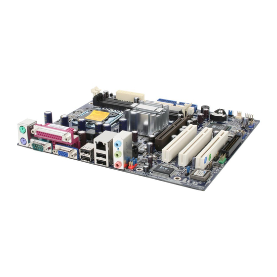
Chapter 1 Product Introduction Motherboard Layout 15 16 17 18 1. CD_IN Connector 15.Front Panel Connector 2. Front Audio Connector 16. System Fan Connector 3. PCI Slots 17. Clear CMOS Jumper 4. FWH/LPC Connector(optional) 18. SATA Connector(optional) 5. BIOS TBL_EN Connecor 19. -
Page 12: Rear Panel Connectors
Chapter 1 Product Introduction Rear Panel Connectors This motherboard provides the ports as below: LAN Connector Parallel Port (Printer Port) Line-in jack PS/2 Mouse Connector Line-out jack PS/2 Keyboard Microphone jack Connector Serial Port VGA Port USB 2.0 Ports (COM1) Line-in jack, Line-out jack, Microphone jack When using a 6-Channel sound source, connect the front speaker to the green audio output;... -
Page 13: Chapter 2 Installation Instructions
Chapter 2 Installation Instructions Chapter This chapter introduces the hardware installation process, including the installation of the CPU and memory. It also addresses the connection of your power supply, connection of hard drive and floppy drive data cables, and setting up various other feature of the motherboard. - Page 14 Chapter 2 Installation Instructions Notes: Take note of the following precautions before you install compo- nents or change settings. 1. Use a grounded wrist strap or touch a safely grounded object, such as an attached power supply, before handling compo- nents to avoid damaging them due to static electricity.
-
Page 15: Cpu
Chapter 2 Installation Instructions This motherboard supports Intel ® Pentium ® D/ Pentium ® 4/Celeron ® D Proces- sors in an LGA775 package . Installation of CPU Below is the CPU socket illustration. Follow these procedures to install a CPU. Load lever Load plate Protective cover... - Page 16 Chapter 2 Installation Instructions 3. Hold CPU with thumb and forefinger. Ensure fingers align to socket cutouts. Match the CPU triangle marker to Pin 1 position as shown below. The alignment key also provides the orientation directed function. Lower the CPU straight down without tilting or sliding the CPU in the socket.
- Page 17 Chapter 2 Installation Instructions 5. Close the load plate, and slightly push down the tongue side. 6. Lower the lever and lock it to the load plate, then the CPU is locked completely. Note : Excessive temperatures will severely damage the CPU and system.
-
Page 18: Memory
Chapter 2 Installation Instructions Memory This motherboard includes two 184-pin slots Memory sockets. You must in- stall at least one memory module to ensure normal operation. If you install two modules, they must be the same speed. Mixed memory modules from different manufacturers is not recommended. -
Page 19: Power Supply
Chapter 2 Installation Instructions Power Supply This motherboard uses an ATX power supply. In order to avoid damaging any devices, make sure that they have been installed properly prior to connecting the power supply. 20-pin ATX power connector: PWR1 20-pin ATX power connector PWR1 is the ATX power supply connector. -
Page 20: Other Connectors
Chapter 2 Installation Instructions Other Connectors This motherboard includes connectors for FDD devices, IDE HDD devices, USB devices, IR module, CPU fan, system fan and others. FLOPPY Connector This motherboard includes a standard FDD connector, supporting 360K, 720K, 1.2M, 1.44M, and 2.88M FDDs. HDD connectors: PIDE &... - Page 21 Chapter 2 Installation Instructions Front Panel Connector: FP1 This motherboard includes one connector for connecting the front panel switch and LED indicators. Hard Disk LED Connector(HDD_LED) The connector connects to the case’s IDE indicator LED indicating the activity status of IDE hard disk. Reset Switch (RESET) Attach the connector to the Reset switch on the front panel of the case;...
- Page 22 Chapter 2 Installation Instructions S-ATA Connectors: SATA_1, SATA_2(optional) The Serial ATA connectors are used to connect the S-ATA devices to the motherboard. These connectors support the thin Serial ATA cables for primary internal storage devices. The cur- rent Serial ATA interface allows up to 150MB/s SATA_1,SATA_2 data transfer rate.
- Page 23 Chapter 2 Installation Instructions Audio Interface: F_AUDIO The audio interface provides two kinds of audio output choices: the Front Audio, the Rear Audio. Their priority is sequenced from high to low (Front MIC_IN MIC_GND MIC_PWR +5VA Audio to Rear Audio). If headphones are plugged AUD_OUT_R AUD_RET_R into the front panel of the chassis (using the Front...
-
Page 24: Expansion Slots
Chapter 2 Installation Instructions Expansion Slots This motherboard includes three 32-bit master PCI bus slots, one AGP slot. PCI Slots The expansion cards can be installed in the three PCI slots. When you install or take out such cards, you must make sure that the power plug has been pulled out. -
Page 25: Jumpers
Chapter 2 Installation Instructions Jumpers The users can change the jumper settings on this motherboard if needed. This section explains how to use the various functions of this motherboard by changing the jumper settings. Users should read the following contents carefully prior to modifying any jumper settings. - Page 26 Chapter 2 Installation Instructions BIOS TBL ENABLE Jumper:TBL_EN The system cannot boot, if the BIOS failed to be BIOS TBL flashed in conventional flash BIOS process. You Disabled will have no such worry when using the BIOS TBL function, which is used to protect BIOS “Top Boot Block”.
- Page 27 Chapter 2 Installation Instructions Starting up for the first time 1. After making all the connections, replace the system case cover. 2. Be sure that all switches are off. 3. Turn on the devices in the following order. Monitor External SCSI devices (starting with the last device on the chain) System power 4.
-
Page 28: Chapter 3 Bios Description
Chapter 3 BIOS Description Chapter This chapter tells how to change system settings through the BIOS Setup menus. Detailed descriptions of the BIOS parameters are also provided. You have to run the Setup Program when the following cases occur: 1. An error message appears on the screen during the system POST process. -
Page 29: Enter Bios Setup
Chapter 3 BIOS Description Enter BIOS Setup The BIOS is the communication bridge between hardware and software, correctly setting up the BIOS parameters is critical to maintain optimal system performance. Power on the computer, when the following message briefly appears at the bottom of the screen during the POST (Power On Self Test), press <Del>... - Page 30 Chapter 3 BIOS Description Advanced BIOS Features The advanced system features can be set up through this menu. Advanced Chipset Features The values for the chipset can be changed through this menu, and the sys- tem performance can be optimized. Integrated Peripherals All onboard peripherals can be set up through this menu.
-
Page 31: Standard Cmos Features
Chapter 3 BIOS Description Standard CMOS Features This sub-menu is used to set up the standard CMOS features, such as the date, time, HDD model and so on. Use the arrow keys select the item to set up, and then use the <PgUp> or <PgDn> keys to choose the setting values. Standard CMOS Features Menu Date This option allows you to set the desired date (usually as the current date) - Page 32 Chapter 3 BIOS Description Award (Phoenix) BIOS can support 3 HDD modes: CHS, LBA and Large or Auto mode. For HDD<528MB For HDD>528MB & supporting LBA (Logical Block Addressing) Large For HDD>528MB but not supporting LBA Auto Recommended mode Drive A/B This option allows you to select the kind of FDD to be installed, including “None”, [360K, 5.25 in], [1.2M, 5.25 in], [720K, 3.5 in], [1.44M, 3.5 in] and [2.88 M, 3.5 in].
-
Page 33: Bios Features
Chapter 3 BIOS Description BIOS Features BIOS Features Menu v[SuperBoot] SuperBoot SuperBoot allows system-relevant information to be stored in CMOS upon the first normal start-up of your PC, and the relevant parameters will be restored to help the system start up more quickly on each subsequent start-up. v[SuperBIOS-Protect] SuperBIOS-Protect SuperBIOS-Protect function protects your PC from being affected by viruses, e.g. -
Page 34: Advanced Bios Features
Chapter 3 BIOS Description Advanced BIOS Features Advanced BIOS Features Menu vCPU Feature Press enter to set the items of CPU feature. vHard Disk Boot Priority This option is used to select the priority for HDD startup. After pressing <Enter>, you can select the HDD using the <PageUp>/<PageDn> or Up/ Down arrow keys, and change the HDD priority using <+>... - Page 35 Chapter 3 BIOS Description vCPU L2 Cache ECC Checking This option is used to enable or disable CPU L2 cache ECC checking. vFirst/Second/Third Boot Device This option allows you to set the boot device’s sequence. vBoot Other Device W ith this function set to enable, the system will to boot from some other devices if the first/second/third boot devices failed.
- Page 36 Chapter 3 BIOS Description vSecurity Option W hen it is set to “Setup”, a password is required to enter the CMOS Setup screen; W hen it is set to “System”, a password is required not only to enter CMOS Setup, but also to start up your PC. vAPIC Mode This option is used to enable or disable APIC mode.
- Page 37 Chapter 3 BIOS Description CPU Feature Menu vDelay Prior to Thermal This option is used to set the delay time before the CPU enters auto thermal mode. vThermal Management This option is used to manage Prescott CPU thermal. Note: This option will not be displayed until a Prescott CPU has been installed. vTM2 Bus Ratio Represents the frequency bus ratio of the throttled performance state that will be initiated when the on-die sensor goes from not hot to hot.
-
Page 38: Advanced Chipset Features
Chapter 3 BIOS Description Advanced Chipset Features Advanced Chipset Features Menu vDRAM Clock/Timing Control Press enter to set the items about DDR RAM. vAGP & P2P Bridge Control Press enter to set the items about AGP. vOnChip AGP Control Press enter to set the items about onchip AGP. vSystem BIOS Cacheable Select “Enabled”... - Page 39 Chapter 3 BIOS Description DRAM Clock/Timing Control Menu vDRAM Timing control This option determines DRAM timing using SPD or manual configuration. Only set as manual, the following 4 items can be updated. vDRAM CAS Latency This option determines CAS Latency. vRAS Active Time (tRAS) This option determines RAS active time.
- Page 40 Chapter 3 BIOS Description AGP & P2P Bridge Control Menu vAGP Aperture Size This option defines the size of the aperture if you use an AGP graphics adapter. The aperture is a portion of the PCI memory address range dedicated for graphic memory address space.
- Page 41 Chapter 3 BIOS Description OnChip AGP Control Menu vVGA Share Memory Size This option is used to set the onboard VGA share memory size. vGraphics Engin Clock This option is used to set onchip AGP graphics engin clock.
-
Page 42: Integrated Peripherals
Chapter 3 BIOS Description Integrated Peripherals Integrated Peripherals Menu vSIS Onchip IDE Device Press enter to set onchip IDE device. vSIS Onchip PCI Device Press enter to set onchip PCI device. vOnboard SuperIO Device Press enter to set onboard superIO device. IDE HDD Block Mode This option is used to set whether the IDE HDD block mode is allowed. - Page 43 Chapter 3 BIOS Description SIS OnChip IDE Device Menu vInternal PCI/IDE This option is used to set the ports of onboard IDE. vIDE Primary/ Secondary Master/Slave PIO These four items let you assign which kind of PIO (Programmed Input/Output) is used by IDE devices. Choose Auto to let the system auto detect which PIO mode is the best or select a PIO mode from 0-4.
- Page 44 Chapter 3 BIOS Description SIS OnChip PCI Device Menu vSIS USB Controller This option is used to enable or disable SIS USB controller. vUSB 2.0 Supports This option is used to enable or disable USB 2.0. vUSB Keyboard Support This option is used to enable or disable USB keyboard under legacy OS. vUSB Mouse Support This option is used to enable or disable USB mouse under legacy OS.
- Page 45 Chapter 3 BIOS Description Onboard Super IO Device Menu vOnboard FDC Controller This item is used to set whether the onboard FDC controller is enable. vOnboard Serial Port 1/2 This items are used to assign the I/O address and interrupt request(IRQ) for the onboard serial port 1/2.These items cannot be adjusted.
-
Page 46: Power Management Setup
Chapter 3 BIOS Description Power Management Setup Power Management Setup Menu vACPI function ACPI stands for “Advanced Configuration and Power Interface”. ACPI is a standard that defines power and configuration management interfaces be- tween an operating system and the BIOS. In other words, it is a standard that describes how computer components work together to manage system hardware. - Page 47 Chapter 3 BIOS Description vVideo Off Method This option is used to define the video off method. “Blank Screen” mode means that after the computer enters power saving mode, only the monitor will close, however, the vertical and horizontal scanning movement of the screen continues.
- Page 48 Chapter 3 BIOS Description PM W ake Up Events Menu vIRQ [3-7,9-15], NMI This option is used to enable or disable IRQ[3-7,9-15], NMI. vIRQ 8 Break Suspend This option is used to enable or disable IRQ8 break suspend. vRING Power Up Control If this option is enable, it allows the system to resume from a software power down or power saving mode whenever there is an incoming call to an in- stalled fax/modem.
- Page 49 Chapter 3 BIOS Description vPower Up by Alarm This option is used to set the timing of the start-up function. In order to use this function, the start-up password function must be canceled. Also, the PC power source must not be turned off. The setting values are Disabled and Enabled. vMonth Alarm This option is used to set the timing for the start-up month.
-
Page 50: Pnp/Pci Configurations
Chapter 3 BIOS Description PnP/PCI Configurations PnP/PCI Configurations Menu Reset Configuration Data This option is used to set whether the system is permitted to automatically distribute IRQ DMA and I/O addresses when each time that the machine is turned on. vResources Controlled By This option is used to define the system resource control scheme. -
Page 51: Pc Health Status
Chapter 3 BIOS Description PC Health Status PC Health Status Menu vCase Opened Warning This option is used to enable or disable case opened warning function. vCPU THERM-Throttling This option is used to enable or disable CPU THERM-Throttling. vSmart Fan Control This option is used to disable or enable smart fan control function. -
Page 52: Frequency/Voltage Control
Chapter 3 BIOS Description Frequency/Voltage Control Frequency/Voltage Control Menu vCPU Clock Ratio This option is used to set the ratio of an unlocked CPU. Using different CPU, the setting values are different. Note: this option is invisible for locking frequency CPU. vAuto Detect DIMM/PCI Clk This option is used to set whether the clock of an unused PCI/DIMM slot will be disabled to reduce electromagnetic interference. -
Page 53: Load Fail-Safe Defaults
Chapter 3 BIOS Description Load Fail-Safe Defaults Press <Enter> to select this option. A dialogue box will pop up that allows you to load the default BIOS settings. Select <Y> and then press <Enter> to load the defaults. Select <N> and press <Enter> to exit without loading. The defaults set by BIOS set the basic system functions in order to ensure system stability. -
Page 54: Save & Exit Setup
Chapter 3 BIOS Description If you do not want to set a password, just press <Enter> when prompted to enter a password, and in the screen the following message will appear. If no password is keyed in, any user can enter the system and view/modify the CMOS settings. Password Disabled!!! Press any key to continue …... -
Page 55: Chapter 4 Driver Cd Introduction
Chapter 4 Driver CD Introduction Chapter The utility CD that came with the motherboard contains use- ful software and several utility drivers that enhance the motherboard features. This chapter includes the following information: Utility CD content Start to install drivers... -
Page 56: Utility Cd Content
SuperUpdate function can help to update the BIOS through internet directly. B. Adobe Reader C. Norton Internet Security(optional) 3. Manual Click here to browse this manual. 4. Browse CD Click here to browse CD content. 5. Homepage Click here to visit Foxconn motherboard homepage. -
Page 57: Start To Install Drivers
Chapter 4 Driver CD Introduction Start to Install divers Select <Install Driver>, and click to enter the install driver screen. You can select the driver that you want to install and begin the setup steps. Note: The following setup steps are based on Windows XP environment. There may be some differences with other operating systems. - Page 58 Chapter 4 Driver CD Introduction Chapter This chapter will introduce how to use attached software. This chapter includes the following information: SuperStep SuperUpdate SuperLogo...
-
Page 59: Chapter 5 Directions For Bundled Software
Adjust System Fan1 warning Minimize Window criteria Exit Program About SuperStep Adjust CPU Fan warning SuperStep Help criteria Link to FOXCONN Website Adjust System Fan2 Go to Fan warning criteria page Apply the Reset the adjust- warning criteria ments to default... - Page 60 Chapter 5 Directions for Bundled Software Adjust voltages warning criteria (upper limit) Current voltage readings Go to Voltage page Reset the warning Apply the Adjust voltages criteria to default adjustments warning criteria settings (Lower limit) Current CPU Adjust CPU tem- Temperature perature warning criteria...
- Page 61 Chapter 5 Directions for Bundled Software Current PCI Current CPU Express clock Clock Current PCI clock Current CPU Adjust the CPU Ratio External Frequency Reset to the default Go to Apply the settings Clock page adjustments Check for the system to auto- matically provide warning mes- sages...
-
Page 62: Superupdate
Minimize Window Current Exit Program BIOS Information BIOS Update Setting About SuperUpdate SuperUpdate Help Link to Foxconn Website Connect to server Backup system and popup a list of BIOS to an image available BIOSs for file users to download... - Page 63 Chapter 5 Directions for Bundled Software Backup BIOS to local image: 1. Click <Backup> and name your BIOS binary file to backup current BIOS. 2. Click <OK> to finish the backup process. Update BIOS from local image: 1. Click <Load> to load the BIOS file.
- Page 64 Chapter 5 Directions for Bundled Software 2. Click <Update>, the following message will appear. 3. Click <Yes> to backup the current BIOS, then the following picture will appear. 4. Click <OK >, then click <Update>.
- Page 65 Chapter 5 Directions for Bundled Software 5. Now is updating. 6. Click <Restart>.
- Page 66 Chapter 5 Directions for Bundled Software Update BIOS: 1. Click <Latest BIOS> to automatically update the BIOS from the server. 2. The following procedure is the same as Update BIOS from local image.
-
Page 67: Superlogo
The best resolution is 136 x 84 for top-right logo and 640 x 480 or 800 x 600 for full screen logo. Using SuperLogo: Display the Flash Information Minimize Window BIOS Write Exit Program Protect Status About SuperLogo BIOS Flash SuperLogo Help Rom Free Space Link to Foxconn website Go to ROM Info. page... - Page 68 Chapter 5 Directions for Bundled Software Full screen mode Top-Right mode Follow the Boot without logo Wizard to complete the logo update Go to Change Logo page Backup whole Backup Logo BIOS image Follow the Wizard to complete the backup function Go to Backup page Browse a BIN file BIOS image...
- Page 69 Chapter 5 Directions for Bundled Software Chapter This chapter will introduce new functions of BIOS and how to use them in detail. It can further exert the max potential of motherboard to bring you super-value enjoyment. This chapter introduces the following new functions of BIOS: SuperBoot SuperBIOS-Protect SuperSpeed...
-
Page 70: Chapter 6 Special Bios Functions
Chapter 6 Special BIOS Functions SuperBoot SuperBoot technology greatly reduces the long boot process time of computers. A BIOS without SuperBoot has to perform many routines every time when the system starts, such as checking the system core and initializing system peripherals. -
Page 71: Superbios-Protect
Chapter 6 Special BIOS Functions SuperBIOS-Protect The BIOS of the motherboard is contained inside the Flash ROM. Severe vi- ruses such as CIH virus are so dangerous that it may overwrite the BIOS of the motherboard. If the BIOS has been damaged, the system will be unable to boot. W e provide the following solution which protects the system BIOS from being attacked by such viruses. -
Page 72: Superspeed
Chapter 6 Special BIOS Functions SuperSpeed SuperSpeed is a powerful and efficient Easy Technology for PC DIY fans. It offers a friendly interface. The users can also realize in the BIOS setup the CPU core voltage adjustability. Procedures: Correctly install your CPU. Plug in other configurations and restore the system. -
Page 73: Superrecovery
Chapter 6 Special BIOS Functions SuperRecovery SuperRecovery is an easy-to-operate tool for backing up or recovering your hard disk data. It offers simplified user interfaces with hotkey access and allows you to experience unprecedented high security and reliability with extra functions, such as hotkey launch, and powerful anti-virus protection. - Page 74 Chapter 6 Special BIOS Functions Hard Disk Selection: The hard disk selection menu will be displayed after you press the hotkey, listing all the IDE HDDs installed in your system. You can switch the highlight bar to make a selection and press “Enter” to confirm it. Attention: 1) Make sure that you have selected a HDD before entering the main menu.
- Page 75 Chapter 6 Special BIOS Functions Main Menu: Select a HDD to enter main menu. There are five function items, “DIVIDE HID- DEN PARTITION”, “RELEASE HIDDEN PARTITION”, “BACKUP”, “RECOVERY” and “CHANGE PASSWORD”. You can switch the highlight bar to make a selec- tion on the operation which should be performed on the HDD and confirm your selection by pressing <Enter>.
- Page 76 Chapter 6 Special BIOS Functions Attention : 1) All the data will be cleared after division is in process. So you’d better do the division against an empty HDD. 2) At the same time, the HDD capacity will decrease to make space for the hidden partition, which is unavailable for your normal use.
- Page 77 Chapter 6 Special BIOS Functions Backup: Select BACKUP to enter the Backup interface, where you can find the following three sub-function items: “BACKUP CMOS SETUP”, “BACKUP PARTITION TABLE” and “BACKUP HARDDISK DATA”. Switch the highlight bar by pressing the arrow keys to make a selection and then press “Enter”...
- Page 78 Chapter 6 Special BIOS Functions 3. Backup Harddisk Data: 1) If there are active partitions (system partition), you can choose an active partition or the whole disk for backing up. But only one can be taken between the two choices. Old data will be replaced by the newly backed 2) Backing up with the progress bar showing.
- Page 79 Chapter 6 Special BIOS Functions 3) A report with all the critical data on this operation will be listed after backing up is completed. Original Size: The data size loaded in selected partition. Valid Size: The size of valid data. Elapsed Time: How long the process took to complete.
- Page 80 Chapter 6 Special BIOS Functions 1. Recover CMOS Setup: This function can help to restore the latest backup of CMOS settings you made. 2. Recover Partition Table: This function can help to recover all partition tables including extended partitions.
- Page 81 Chapter 6 Special BIOS Functions 3. Recover Hard disk Data: This option is used to restore the backed up data from the hidden partition. 4. Back to Main: This option is used to quit the Recovery interface. CHANGE PASSWORD Introduction: Select CHANGE PASSW ORD to enter the Change Password interface.