Table of Contents
Advertisement
Statement:
This manual is the intellectual property of Foxconn, Inc. Although the
information in this manual may be changed or modified at any time,
Foxconn does not obligate itself to inform the user of these changes.
Trademark:
All trademarks are the property of their respective owners.
Version:
User Manual V1.0 in English for 6497MB series motherboard
P/N: 91-181-U49-M2-0E
Symbol description:
Note: refers to important information that can help you to use motherboard
`
better.
Attention: indicates that it may damage hardware or cause data loss,
and tells you how to avoid such problems.
Warning: means that a potential risk of property damage or physical
injury exists.
More information:
If you want more information about our products, please visit Foxconn's
website: http://www.foxconnchannel.com
1
2005-5-9, 15:18
Advertisement
Table of Contents

Related Manuals for Foxconn 6497MB Series


Summary of Contents for Foxconn 6497MB Series
-
Page 1: More Information
This manual is the intellectual property of Foxconn, Inc. Although the information in this manual may be changed or modified at any time, Foxconn does not obligate itself to inform the user of these changes. Trademark: All trademarks are the property of their respective owners. - Page 2 Item Checklist: Thanks for your purchasing Foxconn’s 6497MB series motherboard. Please check the package; if there are missing or damaged items, contact your distributor as soon as possible. 6497MB motherboard (x1) Foxconn Utility CD (x1) 6497MB User Manual (x1) RAID User Manual (x1) (optional)
-
Page 3: Declaration Of Conformity
Declaration of conformity HON HAI PRECISION INDUSTRY COMPANY LTD 66 , CHUNG SHAN RD., TU-CHENG INDUSTRIAL DISTRICT, TAIPEI HSIEN, TAIWAN, R.O.C. declares that the product Motherboard 6497MB is in conformity with (reference to the specification under which conformity is declared in accordance with 89/336 EEC-EMC Directive) EN 55022/A1: 2000 Limits and methods of measurements of radio disturbance... - Page 4 Declaration of conformity Trade Name: Foxconn Model Name: 6497MB Industry Inc. Responsible Party: Address: 458 E. Lambert Rd. Fullerton, CA 92835 Telephone: 714-738-8868 Facsimile: 714-738-8838 Equipment Classification: FCC Class B Subassembly Type of Product: Motherboard Manufacturer: HON HAI PRECISION INDUSTRY...
-
Page 5: Table Of Contents
Table of Contents Chapter Product Introduction Installation Instructions Chapter Supply ..................... Chapter BIOS Description Standard CMOS Features ................25 BIOS Features ................... Advanced BIOS Features ................Advanced Chipset Features ..............Integrated Peripherals ................Power Management Setup ................. PnP/PCI Configurations ................PC Health Status .................. - Page 6 Warning: 1. Attach the CPU and heatsink using silica gel to ensure full contact. 2. It is suggested to select high-quality, certified fans in order to avoid damage to the motherboard and CPU due high temperatures. 3. Never turn on the machine if the CPU fan is not properly installed. 4.
- Page 7 This manual is suitable for 6497MB motherboard. Each motherboard is carefully designed for the PC user who wants diverse features. with onboard 100M LAN with onbaord 1G LAN with 6 channel audio with 8 channel audio with 1394 function with SATA function with RAID function You can find PPID label on the motherboard.
- Page 8 Chapter Thank you for buying Foxconn’s 6497MB series motherboard. This series of motherboard is one of our new products, and offers superior performance, reliability and quality, at a reason- able price. This motherboard adopts the advanced SiS649 + SiS964/SiS964L chipset, providing users a computer platform with a high integration-compatibility-performance price ratio.
-
Page 9: Chapter 1 Product Introduction
Chapter 1 Product Introduction Main Features Size mATX form factor of 9.6 inch x 8.5 inch Microprocessor Supports Intel Prescott-T processor in an LGA775 package ® Supports FSB at 533/800 MHz Supports Hyper-Threading technology Chipset SiS649(North Bridge) + SiS964/SiS964L (South Bridge) System Memory Two 184-pin DIMM slots Supports up to 2 GB DDR memory... - Page 10 Chapter 1 Product Introduction Onboard 1394 (-E ) (optional) Support hot plug With rate of transmission at 400 Mbps Self-configured addressing Can connect with 2 independent 1394 units synchronously at most Onboard LAN (-L/-K) (optional) Supports 10/100/1000 (-K optional) Mbit/sec Ethernet LAN interface built-in on board Onboard Audio (-6)(optional) AC’97 2.3 Specification Compliant...
- Page 11 Chapter 1 Product Introduction Advanced Features PCI 2.3 specification compliant Supports Windows 2000/XP soft-off Supports PC Health function (capable of monitoring system voltage, CPU temperature, system temperature, and fan speed)
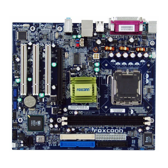
- Page 12 Chapter 1 Product Introduction Layout 1.AUX_IN Connector (optional) 14.ATA 133 /100/66 IDE Connectors 2.CD_IN Connector 15.Serial ATA Connectors (optional) 3.4-pin ATX_12V Power Connector 16.Clear CMOS Jumper 4.CPU Fan Connector 17.System Fan Connector 5.LGA775 CPU Socket 18.Front Panel Connector 6.North Bridge: SiS649/SiS662 Chipset 19.Speaker Connector 7.South Bridge: SiS964 Chipset 20.COM2 Connector...
- Page 13 Chapter 1 Product Introduction Chapter This chapter introduces the hardware installation process, in- cluding the installation of the CPU, memory, power supply, slots, rear panel and pin headers, and the mounting of jumpers. Caution should be exercised during the installation of these modules.
- Page 14 Chapter 2 Installation Instructions This motherboard supports single Pentium 4 Processor including Prescott ® desktop CPUs in an LGA775 package. It also supports Hyper-Threading Technology and FSB Dynamic Bus Inversion (DBI). Installation of CPU Load lever Load plate Load cap Lifted tab...
- Page 15 Chapter 2 Installation Instructions Correct Wrong Lift up the lever. Use thumb to open the load plate. Be careful not to touch the contacts.
- Page 16 Chapter 2 Installation Instructions Note : Excessive temperatures will severely damage the CPU and system. Therefore, you should install CPU cooling fan and make sure that the cooling fan works normally at all times in order to prevent overheating and damaging to the CPU. Please refer to your CPU fan user guide to install it properly.
- Page 17 Chapter 2 Installation Instructions Memory This motherboard includes two 184-pin slots with 2.5 V for DDR. These slots support 256 Mb, 512 Mb and 1 Gb DDR technologies for x8 and x16 devices. You must install at least one memory bank to ensure normal operation. Installation of DDR Memory 1.
-
Page 18: Installation Instructions
Chapter 2 Installation Instructions Power Supply This motherboard uses an ATX power supply. In order to avoid damaging any devices, make sure that they have been installed properly prior to connecting the power supply. 4-pin ATX_12 V Power Connector: PWR2 The ATX power supply connects to PWR2 and 4-pin ATX_12 V power connector provides power to the CPU. -
Page 19: Rear Panel Connectors
Chapter 2 Installation Instructions Rear Panel Connectors This motherboard provides the ports as below: For 6-channel 1394 Port (optional) LAN Port Parallel Port (Printer Port) Line-In PS/2 Mouse Connector Line-Out PS/2 Keyboard Microphone Connector S/PDIF Coaxial USB 2.0 Ports Serial Port Out Port (COM1) For 8-channel... - Page 20 Chapter 2 Installation Instructions S/PDIF Coaxial Out Port This port connects to external audio output devices with coaxial cable connectors. 1394 Port (optional) This digital interface supports electronic devices such as digital cameras, scanners, and printers. USB 2.0 Ports These four Universal Serial Bus (USB) ports are available for connecting USB 2.0/1.1 devices.
- Page 21 Chapter 2 Installation Instructions Other Connectors This motherboard includes connectors for floppy, IDE devices, Serial ATA devices, USB devices, IR module, and others. FDD connector: FLOPPY This motherboard includes a standard FDD connector, supporting 360 K, 720 K, 1.2 M, 1.44 M, and 2.88 M FDDs. HDD Connectors: PIDE &...
- Page 22 Chapter 2 Installation Instructions Front Panel Connector: FP1 This motherboard includes one connector for connect- ing the front panel switch and LED indicators. IDE_LED PLED P W R B T N # R E S E T Empty IDE LED Connector (IDE_LED) The connector connects to the case’s IDE indicator LED indicating the activity status of hard disks.
- Page 23 Chapter 2 Installation Instructions Audio Connectors: CD_IN, AUX_IN (optional) CD_IN, AUX_IN is Sony standard CD audio connectors, it can be connected to a CD-ROM drive through a CD audio cable. CD_R AUX_R CD_L AUX_L CD_IN AUX_IN Speaker Connector: SPEAKER The speaker connector is used to connect speaker of S P K Empty the chassis.
- Page 24 Chapter 2 Installation Instructions Front Audio Connector: F_AUDIO The audio interface provides two kinds of audio AUD_RET-L AUD_OUT-L output choices: the Front Audio, the Rear Audio. Empty Their priority is sequenced from high to low AUD_RET-R AUD_OUT-R +5VA MIC_PWR (Front Audio to Rear Audio). If headphones are MIC_GND MIC_IN plugged into the front panel of the chassis...
- Page 25 Chapter 2 Installation Instructions 1394 Connector: F_1394 (optional) The 1394 expansion cable can be connected to either TPA + TPA - the front (provided that the front panel of your chassis is equipped with the appropriate interface) or rear TPB - TPB + panel of the chassis.
- Page 26 Chapter 2 Installation Instructions Expansion Slots This motherboard includes three 32-bit Master PCI bus slots and one PCI Ex- press x 16 slot. PCI Slots The expansion cards can be installed in the three PCI slots. When you install or take out such cards, you must make sure that the power plug has been pulled out.
- Page 27 Chapter 2 Installation Instructions Jumpers The users can change the jumper settings on this motherboard if needed. This section explains how to use the various functions of this motherboard by chang- ing the jumper settings. Users should read the following content carefully prior to modifying any jumper settings.
- Page 28 Chapter 2 Installation Instructions BIOS Protection Jumper: FWH_EN1 The motherboard BIOS is inside the FWH. If the jumper CLOSED DISABLE FWH_EN1 is set as CLOSED, the system BIOS is pro- tected from being attacked by a serious virus, such as the CIH virus.
-
Page 29: Standard Cmos Features
Chapter This chapter tells how to change system settings through the BIOS Setup menus. Detailed descriptions of the BIOS pa- rameters are also provided. You have to run the Setup Program when the following cases occur: 1. An error message appears on the screen during the system T-- This page is intentionally left blank --his POST process. - Page 30 Chapter 3 BIOS Description Enter BIOS Setup The BIOS is the communication bridge between hardware and software, correctly setting up the BIOS parameters is critical to maintain optimal system performance. Power on the computer, when the following message briefly appears at the bottom of the screen during the POST (Power On Self Test), press <Del>...
- Page 31 Chapter 3 BIOS Description BIOS Features The special features can be set up through this menu. Advanced BIOS Features The advanced system features can be set up through this menu. Advanced Chipset Features The values for the chipset can be changed through this menu, and the sys- tem performance can be optimized.
- Page 32 Chapter 3 BIOS Description Standard CMOS Features This sub-menu is used to set up the standard CMOS features, such as the date, time, HDD model and so on. Use the arrow keys select the item to set up, and then use the <PgUp> or <PgDn> keys to choose the setting values. Standard CMOS Features Menu Date This option allows you to set the desired date (usually as the current date)
- Page 33 Chapter 3 BIOS Description Award (Phoenix) BIOS can support 3 HDD modes: CHS, LBA and Large or Auto mode. For HDD<528MB For HDD>528MB & supporting LBA (Logical Block Addressing) Large For HDD>528MB but not supporting LBA Auto Recommended mode Drive A/B This option allows you to select the kind of FDD to be installed, including [None], [360K, 5.25 in], [1.2M, 5.25 in], [720K, 3.5 in], [1.44M, 3.5 in] and [2.88 M, 3.5 in].
- Page 34 Chapter 3 BIOS Description Memory This is a Display-Only Category, determined by POST (Power On Self Test) of the BIOS. Base Memory The BIOS POST will determine the amount of base (or conventional) memory installed in the system. Extended Memory The BIOS determines how much extended memory is present during the POST.
- Page 35 Chapter 3 BIOS Description BIOS Features BIOS Features Menu [SuperBoot] SuperBoot (Default: Disabled) SuperBoot allows system-relevant information to be stored in CMOS upon the first normal startup of your PC, and the relevant parameters will be restored to help the system start up more quickly on each subsequent startup. The avail- able setting values are: Disabled and Enabled.
-
Page 36: Advanced Bios Features
Chapter 3 BIOS Description Advanced BIOS Features Advanced BIOS Features Menu CPU Feature Press <Enter> to set the items of CPU feature. Please refer to page 30. Hard Disk Boot Priority This option is used to select the priority for HDD startup. After pressing <Enter>, you can select the HDD using the <PageUp>/<PageDn>... - Page 37 Chapter 3 BIOS Description Hyper-Threading Technology (Default: Enabled) This option is used to turn on or off the Hyper-Threading function of the CPU. The available setting values are: Disabled and Enabled. Note: This function will not be displayed until a CPU that supports Hyper- Threading has been installed.
-
Page 38: Advanced Chipset Features
Chapter 3 BIOS Description Advanced Chipset Features Advanced Chipset Features Menu DRAM Clock/Timing Control Press <Enter> to set the sub-items of the DRAM clock/ timing. For details, please refer to page 32. System BIOS Cacheable (Default: Enabled) Select “Enabled” to allow caching of the system BIOS which may improve performance. - Page 39 Chapter 3 BIOS Description DRAM Clock/Timing Control Menu DDR CAS Latency (Default: SPD) When synchronous DRAM is installed, the number of clock cycles of CAS latency depends on the DRAM timing. DRAM Timing Control (Default: Auto) Selects whether DRAM timing is controlled by the SPD (Serial Presence Detect) EEPROM on the DRAM module.
-
Page 40: Integrated Peripherals
Chapter 3 BIOS Description Integrated Peripherals Integrated Peripherals Menu SIS OnChip IDE Device Press the <Enter> key to enter the setup sub-menu. For details, please refer to page 34. SIS OnChip IDE Device Press the <Enter> key to enter the setup sub-menu. For details, please refer to page 35. - Page 41 Chapter 3 BIOS Description SIS Onchip IDE Menu Internal PCI/IDE (Default: Both) This option is used to set the ports of onboard IDE. The available setting values are: Disabled, Primary, Secondary and Both. Primary/Secondary Master/Salve PIO (Default: Auto) These four items let you assign which kind of PIO (Programmed Input/Output) is used by IDE devices.
- Page 42 Chapter 3 BIOS Description SIS Onchip PCI Device Menu SIS USB Controller (Default: Enabled) This option is used to enable or disable SIS USB controller. USB Keyboard/Mouse Support (Default: Enabled) Select “Enabled” if you need to use a USB-interfaced keyboard or mouse in the operating system.
- Page 43 Chapter 3 BIOS Description Onboard SuperIO Device Menu Onboard Serial Port 1/2 (Default: 3F8/IRQ4 /2F8/IRQ3) This option is used to assign the I/O address and interrupt request (IRQ) for the onboard serial port 1/2. Note: Do not try to set the same values for serial ports 1 and 2. UART Mode Select (Default: Normal) Use this option to select the UART mode.
-
Page 44: Power Management Setup
Chapter 3 BIOS Description Power Management Setup Power Management Setup Menu ACPI Function (Default: Enabled) ACPI stands for “Advanced Configuration and Power Interface”. ACPI is a standard that defines power and configuration management interfaces be- tween an operating system and the BIOS. In other words, it is a standard that describes how computer components work together to manage system hardware. - Page 45 Chapter 3 BIOS Description Video Off Method (Default: DPMS Supported) This option is used to define the video off method. “Blank Screen” mode means that after the computer enters power saving mode, only the monitor will close, however, the vertical and horizontal scanning movement of the screen continues.
- Page 46 Chapter 3 BIOS Description PM Wake Up Events Menu RING Power Up Control (Default: Enabled) If this option is enabled, it allows the system to resume from a software power down or power saving mode whenever there is an incoming call to an in- stalled fax/modem.
- Page 47 Chapter 3 BIOS Description Day of Month Alarm This option is used to set the timing for the start-up day of the month. The setting values contain 0 - 31. Time (hh:mm:ss) Alarm This option is used to set the timing for the start-up time. The setting values contain hh:0 –...
-
Page 48: Pnp/Pci Configurations
Chapter 3 BIOS Description PnP/PCI Configurations PnP/PCI Configurations Menu Init Display First (Default: PCI Slot) This item is used to set which display device will be used first when your PC starts up. The available setting values are: PCI Slot and PCIEx. Reset Configuration Data (Default: Disabled) This option is used to set whether the system is permitted to automatically distribute IRQ DMA and I/O addresses when each time the machine is turned... -
Page 49: Pc Health Status
Chapter 3 BIOS Description PC Health Status PC Health Status menu CPU Warning Temperature (Default: Disabled) This option is used to set the warning temperature for the CPU. When the temperature of CPU is higher than setting value, the motherboard will send off warning information. -
Page 50: Frequency/Voltage Control
Chapter 3 BIOS Description Frequency/Voltage Control Frequency/Voltage Control Menu CPU Clock Ratio (Default: based on CPU specifications) This option is used to set the ratio of an unlocked CPU. The possible settings range from a minimum of 0 to a maximum of 50. Note: This option is invisible for locking frequency CPU. -
Page 51: Load Fail-Safe Defaults
Chapter 3 BIOS Description Load Fail-Safe Defaults Press <Enter> to select this option. A dialogue box will pop up that allows you to load the default BIOS settings. Select <Y> and then press <Enter> to load the defaults. Select <N> and press <Enter> to exit without loading. The defaults set by BIOS set the basic system functions in order to ensure system stability. -
Page 52: Save & Exit Setup
Chapter 3 BIOS Description If you do not want to set a password, just press <Enter> when prompted to enter a password, and in the screen the following message will appear. If no password is keyed in, any user can enter the system and view/modify the CMOS settings. PASSWORD DISABLED!!! Press any key to continue …... - Page 53 Chapter The utility CD that came with the motherboard contains use- ful software and several utility drivers that enhance the motherboard features. This chapter includes the following information: Utility CD content Start to Install drivers...
-
Page 54: Chapter Driver Cd Introduction
Chapter 4 Driver CD Introduction Utility CD content This motherboard comes with one Utility CD. To begin using the CD, simply insert the CD into your CD-ROM drive. The CD will automatically display the main menu screen. 1. Install Driver Using this choice, you can install all the drivers for your motherboard. -
Page 55: Start To Install Drivers
C. Norton Internet Security 3. Browse CD Click here to browse CD content. 4. HomePage Click here to visit Foxconn motherboard homepage. Note: 1. Install the latest patch first if your OS is Windows XP or Win- dows 2000. 2. Follow the CD screen order to install your motherboard drivers.