
Related Manuals for Necta Canto Plus Espresso


Summary of Contents for Necta Canto Plus Espresso
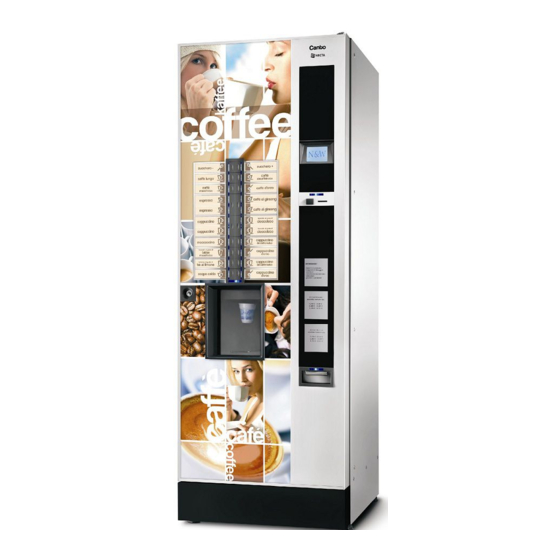
- Page 1 INSTALLATION, OPERATION, MAINTENANCE Canto Plus Espresso English H 3325EN 01 10 - 2009 DITION...
- Page 3 Targhetta di identificazione Identification label Valbrembo, 01/01/2012 DICHIARAZIONE DI CONFORMITA’ DECLARATION OF CONFORMITY DÉCLARATION DE CONFORMITÉ KONFORMITÄTSERKLÄRUNG DECLARACIÓN DE CONFORMIDAD DECLARAÇÃO DE CONFORMIDADE VERKLARING VAN OVEREENSTEMMING Italiano Si dichiara che la macchina, descritta nella targhetta di identificazione, è Direttive europee Sostituita da conforme alle disposizioni legislative delle Direttive Europee elencate a lato e suc- European directives...
-
Page 4: Declaration Of Conformity
Declaration of conformity for use The machine can be used by children and by people having reduced physical, sensorial or mental skills under the supervision of people responsible for their safety or The declaration of conformity with the European Direc- specifically trained on the use of the machine. -
Page 7: Table Of Contents
English TABLE OF CONTENTS PAGE PAGE eclaration of conformity arnings INTRODUCTION PROGRAMMING Dentification of the machine avigation ransport anD storage isplay ositioning of the venDing machine eyboarD oWer on echnical feaTures ormal operation moDe ariable combination lock MAINTENANCE ccessories FILLING AND CLEANING rewer mainTenance oor sWitch eriodical operaTions... -
Page 8: Introduction
IN CASE OF FAILURE In most cases, any technical problem can be solved by Introduction carrying out minor operations. As a consequence, we suggest carefully reading this manual before contacting The technical documentation supplied is an integral the manufacturer. part of the equipment and it must therefore accom- In case of failures or malfunctions that can not be solved, pany the equipment whenever it is either moved please apply to:... -
Page 9: P Ositioning Of The Vending Machine
POSITIONING THE VENDING MACHINE Power supply voltage Power supply frequency The machine is not suitable for installation outdoors. It must be installed in a dry room at a temperature ranging Installed power 2500 from 2°C to 32°C. It can not be installed in a room where water jets are used for cleaning (e.g. - Page 10 onTrols onTainer capaciTy beaned coffee - cup presence stirrers (if any) about 950 - water presence Containers having a 2.45 or 4.5 or 6.5 l capacity or two-compartment containers can be mounted for instant - coffee presence products, according to models. - coffee unit position The indicative product quantity is summed up by the fol- lowing table:...
-
Page 11: Ariable Combination Lock
To change the combination: lecTric energy consumpTion - Open the machine door to avoid forcing the rotation; The electric energy consumption of the machine will depend upon many factors such as the temperature and - Slightly lubricate by using a spray inside the lock; ventilation of the room where the machine is installed, - Insert the current change key (black) and turn it until the inlet water temperature, the boiler temperature, etc. -
Page 12: Filling And Cleaning
Chapter 1 Filling and cleaning The machine is not suitable for installation outdoors. It must be installed in a dry room at a temperature ranging from 2°C to 32°C. It can not be installed in a room where water jets are used for cleaning (e.g. large kitchens, etc.). DOOR SWITCH Whenever you open the door, a special switch will power off the electric installation of the equipment to allow the... -
Page 13: Controls And Information
LOADING CONTROLS AND INFORMATION The machine shall work at a room temperature between 2 and 32 °C. The cup dispenser shelf has got a double articulated The controls and information for the user are arranged joint intended to improve the accessibility to the cup dis- outside the door (see fig. - Page 14 ugar and insTanT producTs Tirrers A self-adhesive plate intended to specify the product is To load the double stirrer stacker correctly, act as follows: arranged on every single container. - remove the external and internal weights for stirrers by After having lifted the cover, pour the products that shall extracting them from the top (see fig.
-
Page 15: Cleaning
CLEANING - to disassemble the impellers, pull slightly to release them (fig. 11); aniTising mixers and food circuiTs The mixers and the conduits for dispensing instant drinks shall be carefully sanitised at the time of the installation of the machine and at least once a week or more frequently, according to the use of the machine and the inlet water quality in order to provide for hygiene on dispensing products. - Page 16 spresso uniT ugar release It is recommended to clean the sugar dispenser by using Whenever you load or at least once a week, it is recom- hot water at regular intervals on the models intended mended to remove any powder residue from the outside to dispense sugar directly in the cup.
- Page 17 ispensing comparTmenT and ixer channels vandal proof device Use a small vacuum-cleaner or a brush to clean the fun- nel area and the container support surface by removing To disassemble the dispensing compartment, unscrew any powder residue at regular intervals. the knurls to release the compartment and let it slide on Surfaces can be cleaned by using a wet piece of cloth.
-
Page 18: Installation
oor swiTch Chapter 2 Whenever you open the door, a special switch will power Installation off the electric installation of the equipment. To power on the machine when the door is open, just Installation and any subsequent maintenance opera- insert the key into the slot (see fig. 15). tion must be carried out when the machine is live and, When the door is open, you are not allowed to therefore, by the personnel skilled and trained on the... -
Page 19: P Late Insertion
LABELS INSERTION To insert the selection labels, disassemble the plate sup- ports after having removed the three fastening screws by acting on fixing clips (see fig. 17). Insert the plates into the slots alternatively opening on the right and left side. Some buttons may not be used according to the models (see the selection dose table). -
Page 20: E Lectrical Connection
ELECTRIC CONNECTION aymenT sysTem assemBly The machine is arranged for electrical operation at a The machine is sold without any payment system. 230 V~ single-phase voltage and it is protected by a 15A As a consequence, only the installer will be liable fuse. -
Page 21: Illing The Water Circuit
FILLING THE WATER CIRCUIT aniTising mixers and food circuiTs for The firsT Time If the air-break should signal no water for over 10 sec. as soon as you power on the machine, the machine will As soon as you install the machine, carefully disinfect automatically perform an installation cycle, i.e.: the mixers, the tubes intended to dispense instant drinks in order to guarantee the hygiene of dispensed products. -
Page 22: Operation
OPERATION For instant drinks you can set up a wait time (from zero to 2000 c/s) after the end of delivery, at the expiry of which the shutter will close. The end-of-delivery sound COMPARTMENT COVER signal is supplied. A microswitch signals the machine the position of the The machine is complete with a cup shift arm that can cup shift arm keep the dispensing nozzles very close to the drink, thus... -
Page 23: Stirrer Sugar Dispenser
STIRRER SUGAR DISPENSER ESPRESSO UNIT Whenever you power on the machine, the coffee unit will The dispenser is driven by a bidirectional motor that will make a complete rotation before performing the normal alternatively release a stirrer from the external stacker cycle to make sure that the device will occupy the initial and a stirrer from the internal one. - Page 24 At the end of the coffee dispensing cycle, the upper pis- eTTing conTrol and regulaTion ton will move down to mechanically compress the used To achieve the best results compared with the product in coffee dose, thus helping water in excess to come out of use, it is recommended to check: the 3rd way of the dispensing solenoid valve.
-
Page 25: Utomatic Grinding Regulation
anual grinding regulaTion If it is necessary to change the grinding degree, act on the corresponding coffee-grinder knob (fig. 26 B) prop- ertly and more precisely: - turn counterclockwise to obtain a coarser grinding degree; - turn clockwise to obtain a finer grinding degree. It is recommended to vary the grinding degree during the operation of the coffee-grinder motor. - Page 26 uTomaTic regulaTion lock rewing Time The coffee dose and water quantity being the same, the You can stop the operation of the automatic regulation, grinding degree will directly affect the brewing time. for whatever reason it might be necessary. If you change this value, the automatic grinding regula- The grinding wheels remain at the distance reached at tion system will act to align the actual time with the one the time when you stop the operation of the automatic...
-
Page 27: S Etup
- Confirm the water dispensing cycle to initialise the pump and the water circuit. - Confirm the execution of the setup procedure. The pump is operated at two different speed rates for a well- defined time interval. - Store the water quantities you have achieved. usTomising drinks If you customise drinks by considerably changing the water dose, check the water flow rate in the mixer. -
Page 28: I Nstant Dispensing Cycle
avigaTion Programming The interaction between the system and the operator notes occurs through the following components:: DISPLAY The electronics intended to control the machine will en- able the operator to use many functions or not. 10-line graphical display intended to display the user The machine programme is intended to describe all messages or the menu functions. - Page 29 KEYBOARD POWER ON According to models, the external keyboard may be by Whenever you power on the machine, the display will way of direct selection or, as an alternative, with numeric show the software release number. keys. If the machine is set to the Filler or Technician mode, the CANTO keys of the selection pushbutton panel will assume the software rev.
- Page 30 FILLER MENU NORMAL OPERATION MODE The message requiring the user to select a drink will ap- Press the programming button on the machine door pear on the display during the normal operation. once to set the machine to the “filler menu” mode. The key function may vary according to the layout and The first item of the “filler”...
- Page 31 The machine code, the date and the software release MANAGEMENT OF CHANGE TUBES will be also printed. To print, act as follows: This function is active only if the payment system - from the print function press key � to display “Do you you have set up can perform this operation.
- Page 32 TECHNICIAN MENU PAYMENT SYSTEMS The main software functions required to manage the ma- You can decide which protocols to enable for the pay- chine operation as well as possible are briefly explained ment systems available and manage the relative func- here below.
- Page 33 xecuTive The BDV protocol menus will enable the user to define ersion the following functions. You have to choose among the following payment sys- tems for the Executive system: mmediaTe change The amount relative to a selection is generally cashed - Standard after the machine has sent the “Successful selection”...
- Page 34 “ ” ” exacT amounT value Used to define the combination of empty tubes intended The MDB protocol menus will enable the user to define to set the coin mechanism to the “exact amount” mode. the following functions. All possible combinations of empty tubes are listed here mmediaTe change below.
- Page 35 oins reTurned arallel machine Used to define which coins shall be used to give the Function used to enable the presence of a validator or change among those available in the tubes. This param- parallel bill reader to recharge the keys. eter is active only with the coin mechanisms not intend- xacT change equaTion ed to manage the choice of the tube in use automatically...
- Page 36 PRICES DOSES From this menu you can set up prices individually (for This group of functions is intended to define all variables every single selection) or globally (the same price for contributing to the drink build-up. all selections) and define the ranges of the promotional time band.
- Page 37 ixer aTer doses To dispense water, act on the following parameters: ixing mode (0 - 3) For every single selection you can set the duration of the venT TarT mixing cycle for every single water dose composing the Set this value to dispense the water of the relative ingre- selection.
- Page 38 ripping ngredienT oTor aliBraTion To convert the product dose values properly, set up the You can define the wait time (you can programme it from flow rate value of every single ingredient motor in gr/s to 0 to 2000 hundredths of a second) from the end of deliv- calculate the grams to be dispensed.
- Page 39 managemenT MACHINE CONFIGURATION This group of functions is intended to manage the basic This group of functions is intended to check all param- data of the machine operation. eters relative to the operation of the machine. niTialisaTion This function shall be used in case of a memory data MACHI N E C O N F I G UR ATI O N error or if the software is replaced.
- Page 40 isplay spresso This group of functions controls all display parameters. grinding anguage Use this function to enable or disable the grinding cycle Use this function to select the language you wish to use of a coffee dose for the next selection. to display the messages among those made available by This will enable the user to reduce the time required to the software.
- Page 41 ashing ccessories naBle The washing key Use this function to enable the operation of the button Use this function to define whether the vending machine intended to wash mixers. is supplied by the network or by internal tanks: They key is generally disabled. 0 - water supply from the network;...
- Page 42 nergy saving asTer lave Choose among the following energy saving options to The control system of the machine is arranged for bank save electric energy whenever the machine is not used: connection with other automatic vending machines (Samba, Samba Top and Diesis) Energy Saving: use this option to interrupt the vending machine service eTup...
- Page 43 achine serial numBer TEST Use this function to change the eight-digit numeric code intended to identify the vending machine (default set to TE ST rogramming The operaTor code TE ST DIS P EN SIN G SP ECIA L F U N CT IO N S When the display is set to the “Operator Code”...
- Page 44 egulaTion of grinding wheels uToTesT Function used to check the operation of the main com- Use this group of functions to check the parameters in- ponents of the machine semiautomatically. Press the tended to regulate the distance between grinding wheels Enter key to display the “AUTOTEST”...
- Page 45 STATISTICS no parameter can be configured for this protocol: lecTronic counTer aTa Transmission Function used to select which communication interface o display The elecTronic counTer to use for the data transfer. The following interfaces are made available: An electronic counter is intended to store all the dispens- ing cycles you have performed since you last reset it in - “RS232”...
- Page 46 eseT relaTive proTocol audiT Statistics can be reset either globally (all types of data) Aud.1 Money in the tubes or selectively, i.e. by: Money currently available in the change tubes - selections Aud 2 Money to the tubes - discounts-overprices Money conveyed to the change tubes - failures Aud 3 Money to the coin box...
- Page 47 COMMUNICATION (Global System for Mobile communications) The control software can send a signal of faulty machine, “prealarms” or “ending product” via GSM modem after a (programmable) well-defined number of dispensing CO M M UNI CAT I ON cycles of a given product. UP - K EY G SM in code...
- Page 48 Cup shift arm FAILURES The machine stops if the cup shift arm should fail to reach 1 of the 2 microswitches within the pre-established time of 15 sec. FAI LU R ES FAI LU R E R EAD O U T Volumetric counter (impeller) FAI LU R E R ES E T The volumetric counter is not counting within a max.
- Page 49 Empty coffee Cup dispenser If the grinder speed should exceed 1200 rev/minute for If the cup sensor photocell is mounted, the “No cup” over 5 seconds, the “empty coffee” failure is recorded. message will appear on the display after having failed You can enable this type of signalling and disable coffee- to dispense a cup for three times.
- Page 50 Short Circuit Mosfet Water Failure The machine fails if a device intended to control direct The water failure is declared during the v.m. standby if current motors on the actuation board (mosfet) remains the water inlet solenoid valve is operated for over 20”. active.
- Page 51 Chapter 3 Maintenance The intactness of the machine and its compliance with the rules of the relative installations shall be checked by skilled personnel at least once a year. Never forget to power off the machine before performing any maintenance operation that may require the disassembly of components.
- Page 52 Disassembling / replacing the upper filter and gas- hannels and mixers At regular intervals, it is necessary not only to remove To disassemble or replace the upper filter and gasket, any powder residue from the parts outside mixing units, act as follows: in particular in the funnel area, but also to sanitise the - Unscrew the side screw (6) intended to fasten the key parts in contact with the mixer drink.
- Page 53 - to disassemble the impellers, just lock and pull slightly ixer nozzles to release them (fig. 32); If it had been necessary to disassemble the instant shelf, pay attention to the nozzle/pump combination in use before during the reassembly phase. Assemble 1-hole nozzles in such a way that the water inlet into the mixer will occur from the lower coupling.
- Page 54 CUP DISPENSER PRODUCT CONTAINERS The cup dispenser is conceived in such a way that it can - Remove the containers from the machine; be easily disassembled for maintenance operations. - Disassemble the product outlet ports and extract the It is possible to disassemble every single column of the Augers from the rear side of the container;...
- Page 55 BOILER MAINTENANCE On reassembling, make sure that: - Electrical contacts (terminals, faston, etc.) are perfectly Descale the boiler at regular intervals, according to the dried and well-tightened; hardness of the mains water and the number of selec- tions you have performed. - Safety and anti-boil thermostats are properly positioned and connected;...
- Page 56 spresso Boiler eplacemenT of grinding wheels only models wiTh auTomaTic grinding regulaTion The espresso boiler has a contact safety thermostat intended to deactivate the boiler heating element if the The function intended to control grinding wheels will dis- boiler temperature should exceed 125°C. play a “Grinding wheel wear”...
- Page 57 BOARD FUNCTION programming After having loaded the software, use the new board to CONFIGURATION OF ELECTRONIC define which type of keyboard to use before initialising or programming the various parameters. BOARDS To access the pre-programming function (keyboard The electronic boards are designed to be used on sev- choice), hold down the pre-programming button (see fig.
- Page 58 c.p.u. Board The C.P.U. (Central Process Unit) board can manage all the users arranged for the maximum configuration as well as the signals coming from the keyboard and the payment system. It can also manage the actuation board. - The LEDs can supply the following information during the operation: - The green LED (26) is flashing on and off during the normal operation of the C.P.U.
- Page 59 cTuaTion Board This board (see fig. 39) is intended to activate the 230 V~ users through relays and the direct current motors directly. Moreover, it can manage the signals from the cams and/or microswitches on the various users. Moreo- ver, it can control the instant boiler relay. The board is supplied at 24Vac.
- Page 60 spresso Boiler conTrol Board urrenT regulaTor Board The board will control the action of the espresso boiler The current regulator board will supply lighting LEDs by heating element. means of direct current. The board is arranged on the espresso shelf. The board will provide for the constant brightness of aesthetic panels.
- Page 61 ESPRESSO WATER CIRCUIT 10- Mixers 1- Water inlet solenoid valve 11- Dispensing nozzles 2- Liquid waste bucket 12- Safety thermostat 3- Vibration pump 13- Anti-boil thermostat 4- Volumetric counter 14- Rotation instant pumps 5- Espresso solenoid valve 15- Air-break 6- Coffee boiler 16- Instant boiler tray 7- Espresso unit 17- Mechanical filter...
- Page 62 PROGRAMMING SUMMARY urfing mode To move inside the menus, use the keys shown by the The machine can work in 3 different operation states: figure: ormal operaTion mode iller menu echnician menu To be able to access the programming menus, press the programming button �...
- Page 63 APPENDIX WIRING DIAGRAMS © by N&W GLOBAL VENDING S.p.A. 01 2013 3325 - 01...
- Page 64 Door connector F 230V T15A F 230V T6,3A 230V 230V 24V-6A N 230V F230V 96 2 MSCB CMSB PSB ITB2 TRASLATORE BICCHIERI 2 TRASLATORE BICCHIERI 1 F 230V J2-2 SM2 J2-3 SM2 SCIROPPI 24Vdc MSB2 MSCB2 IVB2 MSCB CMSB2 UPS/SCIROPPI/ N 230V N 230V This drawing contains confidential informa-...
- Page 65 FOR AUSTRALIA 230-240V 50-60Hz FOR BRASIL AND KOREA 220-230V 60Hz P21A P21A VENT Mvuoto Sled SGANCIO PALETTE/ZUCCHERO TRASLATORE BICCHIERI 1 F 230V T3,15A T200mA MSB2 MSCB2 8,5V VAR PM 230V UPS/SCIROPPI/RISC. SCIROPPI RISC. N 230V MODEL DEFINITION DATE SHEET PREPARED CHECKED Canto SCHEMA ELETTRICO - WIRING DIAGRAM...
- Page 66 F 230V REL1 REL1 NTCS REL1 CALDAIA SOLUBILI MENSOLA FR N 230V N 230V F 230V STRC 90 3 ESC2 MAC2 VENT This drawing contains confidential informa- is drawing contains confidential information and is tion and is the property of the holding the property of the company of N&W or one of its subsidiaries, holding company of N&W or one of its...
- Page 67 MENSOLA FRULLINI MENSOLA DOSATORI N 230V F 230V ESC2 MMA1 MMA2 MAC2 STRC ESPRESSO MD5 MD4 MD3 MD2 MD1 Z4000 FOR AUSTRALIA 230-240V 50-60Hz ESC2 FOR BRASIL AND KOREA 220-230V 60Hz MODEL DEFINITION DATE SHEET PREPARED CHECKED Canto SCHEMA ELETTRICO - WIRING DIAGRAM BREMBILLA MONGUZZI 03/06/2008...
- Page 68 This drawing contains confidential informa- tion and is the property of the holding company of N&W or one of its subsidiaries, without whose permission it may not be copied or disclosed to third parties of otherwise used. This drawing has to be returned promptly upon request to N&W SX 6085 487 01 BDV COIN MECH CONNECTOR...
- Page 69 Canto SCHEMA ELETTRICO - WIRING DIAGRAM Porta - Door WASHING BUTTON RS232 SERIAL PORT “PRIMING” BUTTON SALIM POWER SUPPLY UNIT BOARD STATISTICS BUTTON SLED LED BOARD CUPS SHIFTER BUTTON C.P.U. BOARD...
- Page 70 ___________________________________________ ___________________________________________ ___________________________________________ ___________________________________________ ________________________________________________ ________________________________________________ ________________________________________________ ________________________________________________ ________________________________________________ ________________________________________________ ________________________________________________ ________________________________________________ ________________________________________________ ________________________________________________ ________________________________________________ ________________________________________________ ________________________________________________ ________________________________________________ ________________________________________________ ________________________________________________ ________________________________________________ ________________________________________________ ________________________________________________ ________________________________________________ ________________________________________________ ________________________________________________ ________________________________________________ ________________________________________________ ________________________________________________...
- Page 71 The Manufacturer reserves the right to modify the features of the equipment described in this publication without giv- ing any prior notice. Moreover, it disclaims all responsibility for any inaccuracy contained in this publication that can be ascribed to printing and/or transcription errors. All instructions, drawings, tables and information in general contained in this publication are confi...