
Related Manuals for Necta Samba Top


Summary of Contents for Necta Samba Top
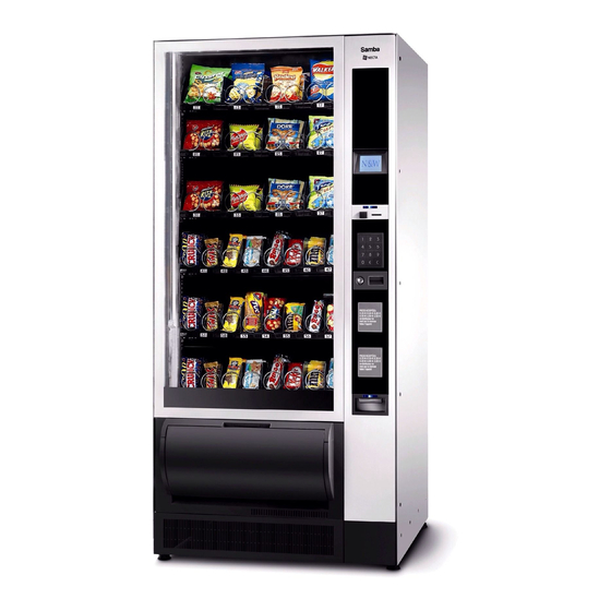
- Page 1 InstallatIon, oPERatIon, MaIntEnanCE Samba English H3335EN00 12 - 2008 dition...
- Page 3 Italiano Direttive europee European directives English Français Deutsch Español Português Nederlands Italiano Harmonised standards tions English Français Deutsch Español Português Nederlands ANTONIO CAVO...
-
Page 4: Declaration Of Conformity
Declaration of conformity for use T�� ������� ��� b� �s�� b� �������� ��� b� ������ having reduced physical, sensorial or mental skills under ��� s����v�s��� �� ������ ��s���s�b�� ��� ����� s����� �� T�� ����������� �� ���������� ���� ��� �������� ������ ��... -
Page 7: Table Of Contents
English TablE of coNTENTS PagE PagE fillEr mENu dEclaration of conformity warnings statistics iNTroducTioN sElEction pricEs managEmEnt of changE tubEs idEntification of thE machinE and its fEaturEs spEcial sElEctions in casE of failurE tEst transport and storagE using thE vEnding machinEs Evadts transfEr positioning thE vEnding machinE tEcHNiciaN mENu... -
Page 8: Introduction
iN caSE of failurE In most cases, any technical problem can be solved by introduction carrying out minor operations. As a consequence, we suggest carefully reading this manual before contacting The technical documentation supplied is an inte- the manufacturer. gral part of the equipment and it must therefore In case of failures or malfunctions that can not be solved, accompany the equipment whenever it is either please apply to:... -
Page 9: Using The Vending Machines
uSiNg THE VENdiNg macHiNES of PoSiTioNiNg THE VENdiNg macHiNE HErmETically SEalEd ProducTS The machine is not suitable for installation outdoors. It must be installed in a dry room at a temperature ranging The control electronics of the machine enables you to from 5°C to 34°C. - Page 10 TEcHNical fEaTurES Height 1830 Width Depth Overall dim. with open door 1495 Overall dim. with open slide-in comp. 1205 Loadless weight Power supply voltage V∿ Power supply frequency Absorbed current Absorbed power maximum operating conditions: Room temperature °C Relative humidity cooling system: Compressor refrigerating capacity Ventilated evaporator...
-
Page 11: Variable Combination Lock
VariablE combiNaTioN locK ccEssoriEs A wide range of accessories can be mounted on the Some models are supplied with a variable combination machine to vary its performances: lock. The assembly kits are supplied with mounting and test- The lock is complete with a silver key for normal opening ing instructions that shall be strictly followed to preserve and closing operations. -
Page 12: Filling And Cleaning
coNTrolS aNd comPoNENTS chapter 1 The controls and information for the user are arranged filliNg aNd clEaNiNg outside the slide-in compartment (see fig. 4). The credit and all operation messages are displayed. The machine is not suitable for installation outdoors. It The selection keyboard is of a numeric type. -
Page 13: Configuration Of Spiral Trays
coNfiguraTioN of SPiral TrayS According to the size of products you wish to dispense, each machine can be fitted with a variable number of dispensing trays (maximum 7), trays and spirals having a different pitch. Fig. 5 Tray Mobile walls Right-hand spiral Left-hand spiral Spirals can be housed either in 152 mm. - Page 14 dispense bottles and cans, plastic bottles up to 69 mm dispense sandwiches. in diameter and 0.2l tetrapacks. Sandwich trays are suitable for dispensing sand- these compartments can be recognised by the pres- wiches only; these trays can be recognised by the ence of a product raised support (see fig.
-
Page 15: Configuration Of Multimax Trays
coNfiguraTioN of mulTimax TrayS some models may have belt trays only used for dis- pensing bottles and cans. Belt trays are composed by 1 single compartment and 4 double compartments: a single compartment may include products, the diam- eter of which lies between 62 and 70mm. double compartments may include products, the diam- eter of which lies between 66 and 70mm. -
Page 16: Loading Spiral Trays
SofTVENd loadiNg SPiral TrayS is available in some models only. oftvEnd sNack proDucts In its home position, is generally as high as the softvEnd lower tray. Extract one tray at a time by lifting and pulling it past the to load trays, act as follows: retaining slide. - Page 17 Push in the trays completely. Make sure that they go fooD proDucts past the retaining slide. the food area can be recognised by the plates on the The sealed edge of bags may be caught under the spi- dividing tray. ral, thus preventing the bag from falling down.
-
Page 18: Loading Sandwich Trays
loadiNg SaNdWicH TrayS loadiNg mulTimax TrayS some models can have sandwich trays, specifically some models can have trays specifically used multimax conceived for dispensing sandwiches oNly. for dispensing bottles and cans oNly. It is recom- Sandwiches shall be loaded into the machine food area. mended to use trays for these types of products multimax... -
Page 19: Power On
PoWEr oN clEaNiNg THE VENTilaTioN gridS of THE cooliNg SySTEm Whenever you power on the machine, the machine electronics will: Clean the ventilation grid of the cooling system at least check the number of trays you have actually connected every 30 days by using a vacuum-cleaner or com- pressed air. -
Page 20: Installation
PaymENT SySTEm aSSEmbly chapter 2 iNSTallaTioN The machine is sold without any payment system. as a consequence, only the installer will be liable for any damage that may be caused to the machine installation and any subsequent maintenance op- or to things and persons by an incorrect installation eration must be carried out by the personnel skilled of the payment system. -
Page 21: Electrical Connection
ElEcTric coNNEcTioN iNTErNal comPoNENTS the machine is arranged for electrical operation at a 230 The evaporator unit on the shelf of the refrigerated box is V~ single-phase voltage and it is protected by T6.3A composed by two fans, the evaporator, the air conveyor fuses. -
Page 22: Cooling Unit
The display will show the following in sequence: ture will vary according to the number and position of software release shutters. uNiform tEmpEraturE saMBa toP One single temperature in the whole box: cool air distri- software rev. x.x bution grid completely open. stratifiED tEmpEraturE presence of the photocells intended to detect the dis- Maximum 3 areas at various temperatures (0-4°C for... -
Page 23: Spiral Trays
oPEraTioN diSPENSiNg comParTmENT locK some models are complete with a device intended to SPiral TrayS lock the dispensing compartment that is electrically released after a dispensing cycle (see the compartment To dispense a product included in a spiral compartment: lock parameters) to open the compartment manually to the motor intended to rotate the spiral is activated. -
Page 24: Programming
NaVigaTioN modE programming the interaction between the system and the operator notes occurs through the following components: the electronics intended to control the machine will en- Display able the operator to use many functions or not. 10-line graphical display intended to display the user the machine programme is intended to describe all messages or the menu functions. -
Page 25: Direct Selection Keyboard
� to move from a menu to a sub-menu or to confirm the execution of a command. Exit kEy � saMBa toP � to go back from a sub-menu to a higher level menu or software rev. x.x not to execute the active command for the time being. -
Page 26: Normal Operation Mode
Normal oPEraTioN modE fillEr mENu the machine is set to the normal operation mode when Press the programming button on the machine door the machine is supplied and the slide-in compartment of once to set the machine to the “filler menu” mode. payment systems is closed. -
Page 27: Selection Prices
isplay STaTiSTicS The function is intended to sequence-display the same all the machine operation data are stored in total and data you can obtain by printing statistics. relative counters that can be reset without losing total Press the Enter key � to sequence-display the following data. -
Page 28: Management Of Change Tubes
maNagEmENT of cHaNgE TubES SPEcial SElEcTioNS From this menu you can manually load or empty the change tubes of the coin mechanism. s PECIa l s El ECtIo n s V ir tu al s e le ct ion s V ir tu al pr ice re tu r n t u B E ManaGE M E n t two -mo to r s e le ctio ns... -
Page 29: Evadts Transfer
Photocells: If the device intended to detect the product TEST passage is available, the light beam readout and inter- ruption are checked. From this menu you can carry out a series of tests to check the correct operation of the various machine Compartment lock: If the device intended to prevent devices. -
Page 30: Technician Menu
TEcHNiciaN mENu PaymENT SySTEmS The main software functions required to manage the ma- You can decide which protocols to enable for the pay- chine operation as well as possible are briefly explained ment systems available and manage the relative func- here below. - Page 31 aliDator The BDV protocol menus will enable the user to define mmEDiatE cHaNgE the following functions. The amount relative to a selection is generally cashed mmEDiatE cHaNgE after the machine has sent the “Successful selection” signal. The amount relative to a selection is generally cashed If you enable this function, which is disabled by default, after the machine has sent the “Successful selection”...
- Page 32 “ ” Exact amouNt valuE The MDB protocol menus will enable the user to define Used to define the combination of empty tubes intended the following functions. to set the coin mechanism to the “exact amount” mode. All possible combinations of empty tubes are listed here mmEDiatE cHaNgE below.
- Page 33 oiNs accEptED salE used to give evidence that cash transactions have oc- Used to define which coins shall be accepted among curred by means of a cashless system. those recognised by the validator when the change The values available are listed here below: tubes are full.
- Page 34 iNimum tubE lEvEl ExEcutivE valiDators Used to set a number of coins between 0 and 15 in order These systems enable you to manage not only the to establish the status of full change tubes and to warn standard price list, but also a promotional price list if the the user to “insert the exact amount”.
-
Page 35: Machine Configuration
DEfrost macHiNE coNfiguraTioN The function allows for a 20-minute defrost cycle (the This group of functions is intended to check all param- cooling unit is powered off, regardless of the tempera- eters relative to the operation of the machine. ture). the time interval between one cycle and the other one can be programmed from 0 to 99 hours (every 6 hours MaCH I nE C on F I Gu R atI o n... - Page 36 maNagEmENt isplay This group of functions is intended to manage the basic This group of functions controls all display parameters. data of the machine operation. laNguagE iNitialisatioN Use this function to select the language you wish to use This function shall be used in case of a memory data to display the messages among those made available by error or if the software is replaced.
- Page 37 ENu maNagEmENt rotatioN sElEctioNs Use this function to create 6 groups of several spirals passworD that are activated by rotation by means of the same It is a 5-digit numeric code you are required to enter to selection number to increase the autonomy of the same display all “advanced”...
- Page 38 softvEND paramEtErs HotocEll paramEtErs The machine can be fitted (as a standard or as an op- From this group of functions you can define as follows: tion according to the models) with a device intended to Enable the use of for every single tray or for softvEnd detect the passage of dispensed products by means of...
- Page 39 nErgy saving astEr lavE 2 power off time bands can be programmed on a weekly The control system of the machine is arranged for bank basis. The days of the week are identified by a progres- connection with other automatic vending machines by sive number (1=Monday, 2=Tuesday etc.).
- Page 40 Photocells: to check the device intended to detect the TEST product passage. The interruption of the light beam is detected. This group of functions is intended to test the main com- ponents of the machine. Compartment lock: press key � to lock the compart- ment and key �...
- Page 41 Eva-Dts DElEtE statistics Two codes are used to identify the machine and recog- Statistics can be reset either globally (all types of data) nise the data transfer terminal according to the EVaDts or selectively, i.e. by: (European Vending Association Data Transfer System) 1 - counter by single selection;...
- Page 42 bdV protocol audit ElEtE rElativE statistics The coin mechanism data are intended to supply the fol- Statistics can be reset either globally (all types of data) lowing information in real currency: or selectively, i.e. by: Aud. 1 Money in the tubes 1 - counter by single selection;...
- Page 43 mdb protocol audit commuNicaTioN Aud. 1 Money in the tubes This menu is intended to group the communication func- money currently available in the change tubes tions of the device by means of Upkey and GSM (Global Aud. 2 Money to the tubes System for Mobile communications).
- Page 44 failurES The control software can send a signal of faulty machine, The machine is equipped with several sensors intended “prealarms” or “ending product” via GSM modem after to control the various functional units. a (programmable) well-defined number of dispensing As soon as a malfunction is found out, the type of failure cycles of a given product.
- Page 45 belt errors : (models with trays only) multimax ailurE rEsEt the machine sets the selections associated with the Function used to reset all current failures, if any. faulty motor out of service in the following cases: otor Errors - faulty motor or not connected - high current absorption (short-circuit) Use this function to display faulty motors for about 1 - time out (the photocells fail to detect the product...
-
Page 46: Spiral Trays
SPiral TrayS chapter 3 maiNTENaNcE ProducT SPacEr The spacers must be used to load “narrow” products. the maintenance operations described by this chapter Mount them in such a way that they can contain the shall be performed when the machine is live. This means product - without blocking it - towards the right side of that they shall be carried out by the personnel special- the compartment so that it stays upright. -
Page 47: Product Ejector
ProducT EJEcTor ProducT raiSEd SuPPorT Right and left ejectors must be used for products packed It is recommended to use a product raised support to in bags, such as potato crisps or alike. dispense plastic bottles up to 69mm, cans or 0.2L tetra- As they are hooked at the end of the spiral, they will push packs. -
Page 48: Changing The Tray Configuration
cHaNgiNg THE Tray coNfiguraTioN The configuration of the spirals on each tray can be changed. To shift from two selections with single spirals to one selection with double spirals, act as follows: Remove the tray to be modified. Remove the central wall by pushing it towards the back and by lifting it later on. -
Page 49: Replacing The Spirals
SaNdWicH TrayS rEPlaciNg THE SPiralS to replace the spirals, act as follows: macHiNEs witH softvEND Extract the tray in question. To prevent the sandwich package from interfering during Rotate the spiral in the direction opposite to the ejec- movement, it is recommended to apply the softvEnd tion rotation while holding the plastic support flange still product ejector on the right to the spiral. -
Page 50: Multimax Trays
mulTimax TrayS trays have a fixed configuration: they are com- multimax posed by 1 single compartment and 4 double compart- ments. a single compartment may include products, the diam- eter of which lies between 62 and 70mm. double compartments may include products, the diam- eter of which lies between 66 and 70mm. - Page 51 dEViaTorS DEviators for cl caNs The machine can be supplied with deviators for double macHiNE witH softvEND compartments; deviators enable the product to fall down No can deviator is required. properly from the tray. The use of deviators depends upon the presence or macHiNE witHout softvEND Mount the can deviators into the corresponding seats absence of...
-
Page 52: Removing The Trays
rEmoViNg THE TrayS cHaNgiNg THE NumbEr of TrayS To modify the configuration of trays, remove the trays The vending machines are supplied with 6 or 7 trays. from the machine. To remove the trays, act as follows: However, you can change the number of trays by acting as follows: extract the tray as far as the limit stop... -
Page 53: Reclining Trays
rEcliNiNg TrayS uNiform tEmpEraturE spiral trays are complete with a leverage system that If you wish to have a uniform temperature in the box enables the operator to recline them to the bottom to (8-16°C or 0-4°C if the food management is active), the facilitate the load cycle. -
Page 54: Board Functions
BOARD funCTIOnS The C.P.U. board, the actuation board and the glassfront lighting board are arranged in the slide-in compartment of payment systems. Open the slide-in compartment to access the boards. Cpu BOARD The board is complete with some LEDs that can supply the following information during the operation: - the green LED (26) is flashing on and off during the normal operation of the C.P.U. -
Page 55: Actuation Board
ACTuATIOn BOARD The actuation board (see fig. 41) is only arranged in the models also complete with belt trays. This board manages: Motors of spiral trays Motors of belt trays Dispensing compartment lock device Motor-driven dispensing compartment (if available) (if available) softvend The board is complete with some LEDs that can supply the following information during the operation:... -
Page 56: Software Update
SofTWarE uPdaTE accESS To THE mulTimax Tray ElEcTromagNETS The machine is equipped with Flash EPROM’s that can be electrically rewritten. the jaws of every single compartment are operated by Use a proper program and system (personal Computer, the respective electromagnets beneath the belt compart- Up Keys or alike) to rewrite the machine management ments. -
Page 57: Access To The Cooling Unit
accESS To THE cooliNg uNiT If you have to access the cooling unit from the machine for any reason whatsoever, please act as follows: Detach the machine from the mains Remove the feet cover (unscrew the fastening screw) Remove the vandal-proof grid Remove the screws intended to fasten the product dispensing compartment and extract it. -
Page 58: Programming Menu Summary
ProgrammiNg mENu Summary NaVigaTioN modE To move inside the menus, use the keys shown by the The machine can work in 3 different operation states: figure: - Normal operation mode; - filler menu; - Technician menu. To be able to access the programming menus, press the programming button on the slide-in compartment of payment systems (see fig. - Page 59 “FIllEr MENU” SUMMAry 1 - STATISTICS 1.1 - STATIST.PRINTING 1.1.1 - PARTIAL PRINTING 1.1.1.1 - SELECT. COUNT. 1.1.1.2 - BAND COUNTER 1.1.1.3 - FAILURE COUNT. 1.1.1.4 - COIN MECH.DATA 1.1.1.5 - PRINT PHOT. ERR. 1.1.1.6 - PRINT MOTOR ERR. 1.1.2 - TOTAL PRINTING 1.2 - PRINT REL.STATS.
- Page 60 “FIllEr MENU” SUMMAry 1.4 - DISP.REL.STATS. 1.4.1 - SEL.COUNT.DISPL. 1.4.1.1 - COUNT X S. SEL. 1.4.1.2 - TOT.COUNT DISPL. 1.4.2 - DISP.BAND COUNT. 1.4.3 - FAILURE COUNT. 1.4.4 - COIN MECH.DISPL. 1.4.4.1 - AUDIT DATA DISP. 1.4.4.2 - CASH COUNT.DISP. 1.4.5 - PHOT.ERR.COUNTER 1.4.6 - MOT.ERR.COUNTER 1.5 - CANC.RELAT.STATS...
- Page 61 “FIllEr MENU” SUMMAry 4 - SPECIAL SELECT. 4.1 - VIRTUAL SELECT. 4.2 - VIRT. PRICE RET. 4.3 - TWO-MOTOR SELECT 4.4 - PHOTOCELL PARAM. 4.4.1 - SETTLING TIME 4.4.2 - MONEY RETURN 4.4.3 - EMPTY SEL.CONTR. 5 - TEST 5.1 - TEST SELECTION 5.2 - MOTOR TEST 5.3 - AUTOTEST 6 - GSM...
- Page 62 “TEChNICIAN MENU” SUMMAry 1 - COIN MECHAN.SET. 2 - PRICES 2.1 - INDIVIDUAL PRICE 2.2 - GLOBAL PRICES 2.3 - TIME SCHEDULE 2.3.1 - TIME BAND 1 2.3.2 - TIME BAND 2 2.3.3 - TIME BAND 3 2.3.4 - TIME BAND 4 3 - DA CONFIGURATION 3.1 - SET DATE &...
- Page 63 “TEChNICIAN MENU” SUMMAry 3.7 - PHOTOCELL PARAM. 3.7.1 - SETTLING TIME 3.7.2 - MONEY RETURN 3.7.3 - EMPTY SEL.CONTR. 3.8 - COMP.LOCK PARAM. 3.8.1 - OPERATING MODE 3.8.2 - UNLOCK TIME 3.8.3 - OUT OF SERV.TIME 3.8.4 - OUT SER. IF OPEN 3.9 - ENERGY SAVING 3.A - V.M.
- Page 64 “TEChNICIAN MENU” SUMMAry 5.3 - STATIST. DISPLAY 5.3.1 - SEL.COUNT.DISPL. 5.3.1.1 - COUNT X S. SEL. 5.3.1.2 - TOT.COUNT DISPL. 5.3.2 - DISP.BAND COUNT. 5.3.3 - FAILURE COUNT. 5.3.4 - COIN MECH.DISPL. 5.3.4.1 - AUDIT DATA DISP. 5.3.4.2 - CASH COUNT.DISP. 5.4 - STATISTICS RESET 5.4.1 - PARTIAL RESET 5.4.1.1 - SELE.COUNT.RESET...
- Page 65 “TEChNICIAN MENU” SUMMAry 5.8 - PRINT REL.STATS. 5.8.1 - PARTIAL PRINTING 5.8.1.1 - SELECT. COUNT. 5.8.1.2 - BAND COUNTER 5.8.1.3 - FAILURE COUNT. 5.8.1.4 - COIN MECH.DATA 5.8.2 - TOTAL PRINTING 6 - COMMUNICATION 6.1 - UPKEY 6.1.1 - UPKEY -> MACHINE 6.1.2 - MACHINE ->...
- Page 66 wIRING DIAGRAM LeGeND INITIALS DESCRIPTION INITIALS DESCRIPTIONe BDV COIN MECH CONNECTOR DOOR MICROSWITCH LOWER LIMIT SWITCH DISP COMPT FLAP MICROSWITCH FILTER CONDENSER COMPRESSOR close CLOSED PRODUCT COMPARTMENT SWITCH PRODUCT COMPARTMENT MOVEMENT MOTOR CM0-9 VENDING MOTOR CAM COMPARTMENT LOCK MOTOR CAM TEMPERATURE PROBE DIODE open...
- Page 67 ___________________________________________ ___________________________________________ ___________________________________________ ___________________________________________ ________________________________________________ ________________________________________________ ________________________________________________ ________________________________________________ ________________________________________________ ________________________________________________ ________________________________________________ ________________________________________________ ________________________________________________ ________________________________________________ ________________________________________________ ________________________________________________ ________________________________________________ ________________________________________________ ________________________________________________ ________________________________________________ ________________________________________________ ________________________________________________ ________________________________________________ ________________________________________________ ________________________________________________ ________________________________________________ ________________________________________________ ________________________________________________ ________________________________________________...
- Page 68 Sx49600...
- Page 70 Sx49700...
- Page 71 Samba Schema elettrico porta Door wiring diagram Plus - Top...
- Page 72 Custom version Sx49802...
- Page 73 Samba Schema elettrico cassetti Trays wiring diagram Plus - Top...
- Page 74 ___________________________________________ ___________________________________________ ___________________________________________ ___________________________________________ ________________________________________________ ________________________________________________ ________________________________________________ ________________________________________________ ________________________________________________ ________________________________________________ ________________________________________________ ________________________________________________ ________________________________________________ ________________________________________________ ________________________________________________ ________________________________________________ ________________________________________________ ________________________________________________ ________________________________________________ ________________________________________________ ________________________________________________ ________________________________________________ ________________________________________________ ________________________________________________ ________________________________________________ ________________________________________________ ________________________________________________ ________________________________________________ ________________________________________________...
- Page 75 The Manufacturer reserves the right to modify the features of the equipment described in this publication without gi- ving any prior notice. Moreover, it disclaims all responsibility for any inaccuracy contained in this publication that can be ascribed to printing and/or transcription errors. All instructions, drawings, tables and information in general contained in this publication are confidential and can be neither entirely nor partially reproduced or transmitted to third parties without the written consent of the Manufacturer who has the sole ownership.