Table of Contents
Advertisement
Quick Links
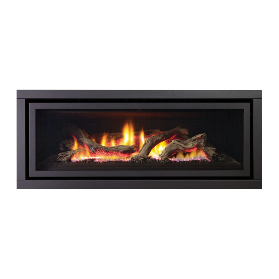
Greenfire
Gas Fireplace
MODELS: GF1500NG Natural Gas
Warning
Fire or explosion Hazard
failure to follow safety warnings exactly could result in serious
injury, death, or property damage.
Do not store or use gasoline or other flammable vapors and liquids in the vicinity of this or any other
appliance.
WHAT TO DO IF YOU SMELL GAS
•
Do not try to light any appliance.
• Do not touch any electrical switch: do not use any phone in your building. Leave the building immediately.
• Immediately call your gas supplier from a neighbour's phone. Follow the gas supplier's
instructions.
• If you cannot reach your gas supplier, call the fire department.
Installation and service must be performed by a qualified installer, service agency or the gas supplier.
920-353b
GF1500L
®
GF1500LLP-2 GF1500LULPG-2 Propane
Installer: Please complete the details on the back cover
and leave this manual with the homeowner.
Homeowner: Please keep these instructions for future reference.
Owners &
Installation Manual
LISTINGS AND CODE APPROVALS
These gas appliances were tested in accordance
with AS/NZS 5263.0 & AS/NZS 5263.1.3/ and
certified by the Australian Gas Association for
installation and operation as described in these
instructions. Must be installed as per AS/NZS
5601.
Your unit should be serviced annually by an
authorised service person.
www.regency-fire.com.au
02.28.22
Advertisement
Table of Contents
Troubleshooting

Related Manuals for Regency Greenfire GF1500NG


Summary of Contents for Regency Greenfire GF1500NG
- Page 1 Must be installed as per AS/NZS 5601. Your unit should be serviced annually by an authorised service person. www.regency-fire.com.au MODELS: GF1500NG Natural Gas GF1500LLP-2 GF1500LULPG-2 Propane Warning Fire or explosion Hazard failure to follow safety warnings exactly could result in serious injury, death, or property damage.
-
Page 2: Pairing Your Remote Control
As it also bears our own mark, it will provide you with economy, comfort, and security for many trouble-free years to come. Please take a moment now to acquaint yourself with these instructions and the many features of your Regency Fireplace. -
Page 3: Warning
WARNING DO NOT turn your fireplace on via any means or allow it to be turned on unless you have conducted a thourough inspection of the area surrounding the fireplace immediately prior to its use, and you have satisfied yourself that there are no materials or other items in proximity to the fireplace which could present a fire risk. -
Page 4: Table Of Contents
Flueing Arrangement for Horizontal Terminations ......27 Rigid Pipe Flueing Systems - Basic Horizontal & Vertical Warranty .................... 68 Terminations ..................28 Flueing Arrangements - Horizontal Termination (Flex) - Regency ® Direct Vent System ................. 29 Horizontal Venting with Two 90 Elbows .......... -
Page 5: Copy Of Data Badge
Check the badge on the unit and if there is a ® difference, the badge on the unit is the correct one. Copy of Data Badge Regency Gas Fireplace Distributed by: Model Western Australia: Air Group Australia... -
Page 6: Unit Dimensions
dimensions Unit Dimensions 633mm 560mm 1263mm 523mm 1151mm Greenfire® GF1500L-2 Gas Fireplace... -
Page 7: Installer's Information
installer's information Important Message 11. Under no circumstances should this appliance YOUNG CHILDREN SHOULD BE CARE- be modified. Parts that have to be removed for SAVE THESE INSTRUCTIONS FULLY SUPERVISED WHEN THEY ARE servicing should be replaced prior to operating IN THE SAME AREA AS THE APPLI- this appliance. -
Page 8: Installation Checklist
installer's information Installation Checklist This includes: 4. The GF1500L Direct Vent Gas Fireplace is approved for alcove installations, see 1. Clocking the appliance to ensure the correct "Clearances" section for details. 1. Locate the appliance: firing rate (noted on label) after burning a) Room location (Refer to "Locating Your Gas appliance for 15 minutes. -
Page 9: Clearances
installation Clearances The clearances listed below are minimum distances unless otherwise stated. A major cause of chimney-related fires is failure to maintain required clearances (air space) to combustible materials. It is of the greatest importance that this fireplace and flue system be installed only in accordance with these instructions. •... -
Page 10: Framing Dimensions
installation Framing Dimensions Dimensions Description GF1500 Framing Height 945 mm combustible finish ¹ Framing Height -Steel Stud 846 mm non combustible steel stud Framing Width 1394 mm Framing Depth 568 mm Minimum Height to Combustibles 1225 mm Corner Wall Depth 1460 mm Corner Facing Wall Width 2065 mm... -
Page 11: Combustible Finishing Unit Assembly/ Finishing/ Mantel Clearances + Mantel Leg Clearances
installation Combustible Finishing Unit Assembly/ Finishing/ Mantel Clearances + Mantel Leg Clearances Unit Assembly Prior To installation The nailing strips must be correctly positioned and attached before unit is slid into position. Nailing Strips-Combustible Finishing The nailing strips come attached to the unit. There is one plate on each side and one on the top. -
Page 12: Framing & Finishing (Combustible)
installation Framing & Finishing (Combustible) • *The finishing trim or one of the fascias must Finished Material be used with combustible finishing. • 10 mm to 19 mm combustible finishing can be used if the 13 mm air gap around the front fac- 1st slot 0mm-19mm thick- ing of the unit is maintained. -
Page 13: Clearances For Combustible Finishing With Mantel
installation Clearances for Combustible Finishing with Mantel Due to the extreme heat this fireplace emits, the mantel clearances are (305mm) (152mm) critical. Combustible finishing and mantel clearances are shown in the diagram on the (576 mm) right. Finishing trim must be used with combustible finishing. (305mm) •... -
Page 14: Non Combustible Flush Finishing - Unit Assembly/Finishing/Mantel Clearances + Mantel Leg Clearances
installation Non Combustible Flush Finishing - Unit Assembly/Finishing/Mantel Clearances + Mantel Leg Clearances Remove top nailing strips & standoffs at side and under- neath 1. Remove the top nailing strip/standoff by removing 4 screws in locations shown in diagram to the right, then lift off and recycle. 2. -
Page 15: Clearances For Non Combustible Flush Finishing With Mantel
installation Clearances For Non Combustible Flush Finishing with Mantel Due to the extreme heat this fireplace emits, the mantel clearances are critical. Combustible mantel clearances from top of front facing are shown in the diagram on the right. • For a flushed finish using non-combustible finishing, seven (305 mm) (152 mm) 13mm stand-off tabs around the fireplace opening must... -
Page 16: Flushed Finishing & Framing With Non Combustible Material
installation Flushed Finishing & Framing with Non Combustible Material • For flush finishing, the top nailing strip must be removed and a non-combustible Finished * diagrams shown below are steel stud support added. Material with top nailing strip removed. 12mm The seven fireplace opening standoffs which are located on this unit can be removed when non combustible material is installed flush with the unit. -
Page 17: Installing A Tv / Artwork Flush With The Unit
installation Installing a TV / Artwork Flush with the Unit Note: All wiring should stay free and clear of the vent system to avoid damage due to heat, if located directly in front of the vent system. Ensure wiring is secured without any sag. Heat deflector must overhang front of TV by 51mm. -
Page 18: Tv Recess With 45 Degree Elbow
• If you do place a television above the fireplace, please be aware of the large amount of heat the fireplace generates. Regency in no way guarantees or takes responsibility for the suitability of the above installation for all homes, or any negative impacts from placing a TV above the fireplace, including damage to the TV. -
Page 19: Optional Framing Kit
installation GF1500L-1 Optional Framing Kit OPTIONAL FRAMING KIT 1. Construct the timber framing, ensure inside dimensions are 1095 mm H x 1394 mm W as shown below. (607-065) Flat side out 5. Secure horizontal steel header stud (606-067) with 2 screws per side as 2. -
Page 20: Non Combustible Facing Installation
• Regency Fireplace Products are designed, produced, tested and certified to the highest industry standards. The finishing of the walls surrounding Regency is as critical as the installation itself. The temperatures around linear gas fireplaces are typically higher than would be acceptable for the combustible materials. Your Regency Fireplace is no exception to this rule. -
Page 21: Framing & Finishing (Clean Finish Installations Only)
installation Framing & Finishing (Clean Finish Installations Only) 1. Frame in the enclosure for the unit with framing material. • The framed opening must be of non-combustible material. • When constructing the framed opening, please ensure there is ac- cess to install the gas lines when the unit is installed. 2. -
Page 22: Exterior Flue Termination Locations
installation Exterior Flue Termination Locations FIGURE 6.2 (in part): LOCATION OF FLUE TERMINALS OF BALANCED FLUE AS/NZ 5601, ROOM-SEALED, FAN ASSISTED, OR OUTDOOR APPLIANCE Greenfire® GF1500L-2 Gas Fireplace... -
Page 23: Exterior Flue Termination Locations - Clearances
installation Exterior Flue Termination Locations - Clearances Minimum clearances (mm) Ref. Item Natural Draught Assisted Below eaves, balconies and other projections: Appliances up to 50 MJ/h input Appliances up to 50 MJ/h input From the ground, above a balcony or other surface* From a return wall or external corner* From a gas meter (M) (see Note 5) (see Clause 5.11, 5.9 for vent terminal location of regulator) -
Page 24: 127 Mm X 203 Mm Rigid Pipe - Cross Reference Chart Only
Not all Rigid Pipe components are available directly from FPI. Components from different Manufacturers may not be mixed. Not all rigid pipe components are available directly from Regency. Note: Olympia Ventis DV venting is only approved for certain models. See list of approved models in cross-reference chart. - Page 25 Snorkel Termination 356 mm 58DVA-SNK14 Snorkel Termination 914 mm 58DVA-SNK36* Restrictor Disk Colinear Flex Connectors * Not available from Regency 946-604/P Simpson Direct Vent or Astro Cap -Vent Guard (Optional) 946-623/P AstroCap XL Horizontal Cap 770-994 Rigid Pipe Adaptor (Must use with all rigid piping)
-
Page 26: Flue Restrictor Settings
installation Flue Restrictor Settings Flue restriction is required for certain venting installations, see the diagrams in the "Flueing Arrangements" section to determine if they are required for your installation. The Flue Restrictor plate is located on the inside top of the firebox. Set 3-(32mm) To set the flue restriction as indicated in the flueing arrangements diagrams, refer to the following instructions;... -
Page 27: Flueing Introduction
installation Flueing Introduction The GF1500L uses the "balanced flue" technology Co-Axial system. The inner liner vents products of combustion to the outside while the outer liner draws outside combustion air into the combustion chamber thereby eliminating the need to use heated room air for combustion and losing warm room air up the chimney. Note: These flue pipes must not be connected to any other appliance. -
Page 28: Rigid Pipe Flueing Systems - Basic Horizontal & Vertical Terminations
installation Rigid Pipe Flueing Systems - Basic Horizontal & Vertical Terminations Rigid Pipe Flue Systems offer a complete line of component parts for installation of both horizontal and vertical installations. Many items are offered in decorative black, as well as galvanized finish. Vertical Terminal The minimum components required for a basic Horizontal Termination are:... -
Page 29: Flueing Arrangements - Horizontal Termination (Flex) - Regency
Flueing Arrangements - Horizontal Termination (Flex) - Regency Direct Vent System ® These flueing systems, in combination with GF1500L, have been tested and listed as a Direct Vent system by AGA. The location of the termination cap must conform to the requirements in the Flue Terminal Locations diagram from the "Exterior Flue Termination Locations" section. -
Page 30: Horizontal Venting With Two 90 Elbows
installation Horizontal Venting with Two 90 Elbows One 90 elbow = Two 45 elbows. Option H + H1 W i t h t h e s e o p t i o n s , 0.3 m Min. 0.9 m Max. maximum total pipe length 0.6 m Min. -
Page 31: Unit Installation With Horizontal Termination (Rigid Flue Systems)
installation Unit Installation with Horizontal 7. Ensure that the pipe clearances to combustible materials are maintained (Diagram 3). Install Termination (Rigid Flue Systems) the termination cap. A top clearance of 76mm and side & bottom The four wood screws provided should be clearance of 51mm must be maintained;... -
Page 32: Unit Installation With Horizontal Termination Flex System
installation Unit Installation With Horizontal Termination Flex System 4. Separate the 2 halves of the wall thimble and • Do not locate termination hood • A top clearance of 76mm and side & bottom securely fasten the one with the tabs to the where excessive snow or ice clearance of 51mm must be maintained;... -
Page 33: Flueing Arrangement For Vertical Terminations - Vertical Flue With Two 90
installation Flueing Arrangement for Vertical Terminations - Vertical Flue with Two 90 Elbows (1 - 90 = 2 - 45 The shaded area in the diagram shows all allowable combinations of straight vertical and offset to vertical terminations, using two bends, with Rigid/Flex Pipe Flueing Systems. -
Page 34: Vertical Venting With Three 90 Elbows
installation Vertical Venting with Three 90 Elbows One 90 elbow = Two 45 elbows. Option H + H1 V + V1 With these options, 0 Min. 0.6 m Max. 0.6 m Min. m a x . t o t a l p i p e 0.3 m Min. -
Page 35: Direct Flue Zero Clearance Top Exit Vertical Flue Kit Installation Instructions
installation Direct Flue Zero Clearance Top Exit Vertical Flue Kit Installation Instructions This flue kit has been manufactured for use with GF1500L and to be installed in accordance with AS/NZS 5601. To ensure safety and correct unit operation this flue kit must be installed as outlined in these instructions. -
Page 36: Unit Installation With Vertical Termination (Rigid Systems)
installation Unit Installation with Vertical Termination (Rigid Systems) 7. Penetrate roof and secure flashing (supplied • A clearance of 50mm must be maintained. • For best results and optimum performance by installer) We recommend framing a 279mm x with each approved flueing system, “Mill- 279mm (inside dimensions) hole to Pac”... -
Page 37: Vertical Termination - 127 Mmx 203 Mm Flueing - Vertical Flex Kit
Termination Cap installation Storm Collar Vertical Termination Flashing 127 mm x 203 mm Flueing - Vertical Flex Vent Kit for Australia (Part # 946-772) Vertical Termination - 127 mmx 203 mm Flueing - Vertical Flex Kit (Part 946-772) Roof support Must choose 1 of the following: Firestop spacer to prevent debris Part #... - Page 38 Vertical Termination 127 mm x 203 mm Flueing - Vertical Flex Vent Kit (946-772) installation installation 13. Slide the finished length up towards the flashing ensuring the length installation 13. Slide the finished length up towards the flashing ensuring the length of Termination Cap of pipe is a minimum of 0.6 m measured from the top of the roof.
-
Page 39: Vertical Flue Extension Kit (Approved) (Part # 946-769)
installation Vertical Flue Extension Kit for Australia Part #946-769 Vertical Flue Extension Kit (Approved) (Part # 946-769) 6.1 m flex pipe extension 127 mm inner pipe - 6.1 m Used in conjunction with the 946-772 Vertical Flex Kit for vertical installations. -
Page 40: High Elevation
Cable GF1500LLP-2 SYSTEM DATA Pilot Ignitor • If you have an incorrect flame pattern, Min. Supply Pressure 2.75 kPa contact your Regency® dealer for further Electric Low Setting Man. 1.6 kPa instructions. Modulator Pressure Incorrect flame pattern will have small, probably Max. -
Page 41: Wiring Diagram (Ng Only)
installation Wiring Diagram (NG Only) • Disconnect power supply to unit prior to working on electrical components. • Ensure that the wires do not touch any hot surfaces and are away from sharp edges. • Label all wires prior to disconnection when servicing controls. Wiring errors can cause improper and dangerous operation. -
Page 42: Conversion Kit From Ng To Propane/Ulpg Using Sit 845 Nova Gas Valve
installation Conversion Kit from NG to propane/ULPG Using SIT 845 NOVA Gas Valve GF1500L-2 CONVERSION KIT FROM NG TO PROPANE/ULPG Refer to instructions provided with conversion kit for most up to date instructions. FOR GF1500L-2 PART #607-967 USING SIT 845 NOVA GAS VALVE THIS CONVERSION MUST BE DONE BY A QUALIFIED GAS FITTER IF IN DOUBT DO NOT DO THIS CONVERSION !! Each Kit contains one Propane / ULPG... - Page 43 GF1500L-2 installation 11. Reinstall new burner orifice Propane/ULPG and tighten. 19. Adjust Air shutter to fully open for both LP/ULPG. Burner Orifice #47 (Propane) 20. Place ECS V module back into the unit and reinstall the access Burner Orifice # 49 (ULPG) panel.
- Page 44 GF1500L-2 installation After carrying out all adjustments, block the setting screws with paint, 25. Apply new wiring diagram decal over existing one on the bottom of taking care not to obstruct the breather orifice of the pressure regulator. the unit. Put the plastic modulator cap back on.
-
Page 45: Optional Wifi App (Part #946-767) - Wifi Dongle Installation
WIFI App / WIFI Dongle Installation Instructions installation Optional WIFI App (Part #946-767) - WIFI Dongle Installation 4. Insert the dongle cable into the controller and make sure it is properly seated. Use this QR code to access our quick start guide. Improperly seated: WiFi dongle/app quick start guide. -
Page 46: Optional Fan Ducting Kit Installation
installation GF1500 Optional Fan Ducting Kit Installation OPTIONAL FAN DUCTING KIT INSTALLATION LISTINGS AND CODE GENERAL INFORMATION Maximum Duct Run: 9.0m Kit Contains 4.5m APPROVALS The Fan Kit increases the effectiveness of your fireplace by dispersing warm air from the fireplace If you require more than 4.5m please purchase Fan This Fan Kit has been approved for use with to remote locations in the same room or other... - Page 47 installation GF1500 OPTIONAL FAN KIT INSTALLATION NOTE: Installation of Fan Kit should be done prior Air Duct to installation of the wall. 2) Mount and secure the fan housing assembly to framing members, the front of the fan housing will protrude 12.7mm out of the wall so it may be finished Fan Housing Round to Oval...
- Page 48 FAN DUCT EXTENSION KIT In order to use the fan extension duct kit, you must have installation fan kit. This kit allows you to extend the fan duct to 9m. 2. Attach the 4.5m duct within this kit to the connecting collar on the opposite 1.
-
Page 49: Log Set Installation
GF1500 installation LOG SET INSTALLATION Log Set Installation Read the instructions below carefully and refer to the images. If the logs are broken do not use the unit until they are replaced. Broken logs can interfere with pilot operation. Improper positioning of the logs may create carbon build-up and can alter the unit's performance which is not covered under warranty. - Page 50 GF1500 installation 5. Line up locator on Log 4 with corresponding locator on Ceramic Log 6. Rest Log 6 on Log 1 and also on the Ceramic log Burner as shown in Burner as shown in Diagram 7. Diagram 10. Diagram 7 Diagram 10 6.
-
Page 51: Front Trim Removal/Installation
installation Front Trim Removal/Installation 1. Remove faceplate, inner door frame, and glass door if already installed - see instructions in this manual. 2. Remove two (2) screws in locations shown below to remove front trim piece. 3. Reverse steps to reinstall. Front Trim Piece Diagram 1 - Front Trim Screw Locations Inner Panel Removal/Installation... -
Page 52: Faceplate And Deflector Installation
GF1500 installation Faceplate and Deflector Installation FACEPLATE AND DEFLECTOR INSTALLATION 1. Install the fascia to the unit by hooking the left and right side • Turn off the unit at the wall switch or mounting brackets into the mounting slots at the side of the remote. -
Page 53: Screen & Inner Door Frame Installation
installation Screen & Inner Door Frame Installation 1. Hang screen mesh over inner door frame as shown in diagram 1. 3. Install screen and inner door frame to unit but hanging over glass door frame as shown in diagram 3. Lower gently once in position over glass door frame. Diagram 1 Diagram 3 2. -
Page 54: Optional Finishing Trim Installation
tooltip installation GF1500L-1 Optional Finishing Trim Installation OPTIONAL FINISHING TRIM INSTALLATION 1. Install the optional finishing trim by lining up trim with the outside of the fascia. Press trim inward firmly to seat onto the unit. Finishing Trim Installed 2. Pull trim outward–away from the unit to remove. Greenfire®... -
Page 55: Operating Instructions
60 second wait. low setting. Use the Regency Remote Control Kit supplied • The fan will not completely turn off on 8. When lighting the appliance, the inside of the glass with this unit. -
Page 56: Copy Of Lighting Plate Instructions
Improper least 5-10 seconds. installation, adjustment, alteration, service Regency gas appliances use high tech fans to push or maintenance can cause injury or property heated air farther into the room. It is not unusual for damage. -
Page 57: Fan Service
maintenance Fan Service 6. Remove access panel by removing eight(8) screws in locations shown PRIOR TO SERVICING THE FAN, ENSURE THAT UNIT HAS COOLED in Diagram 4. TO ROOM TEMPERATURE, ALL POWER IS DISCONNECTED AND GAS SUPPLY IS TURNED OFF. 1. -
Page 58: Maintenance Instructions
* Do not strike or abuse the glass. resistant paint. Regency uses StoveBright ® 3) Check for evidences of excessive condensation, * Do not operate this fireplace without the glass Paint - Metallic Black 938-110. -
Page 59: Glass Door Installation
maintenance Glass Door Installation • Do not operate the appliance with the glass panels removed, cracked or broken. Replacement of the glass panels should be done by a licensed or qualified service person. Glass should be cool, if cleaning is necessary. 1. -
Page 60: Valve Tray Replacement
maintenance Valve Tray Replacement 5. Remove rear log tray by removing 3 screws as shown in Diagram 3 below. PRIOR TO VALVE TRAY REPLACEMENT, ENSURE UNIT HAS COOLED TO ROOM TEMPERATURE, ALL POWER IS DISCONNECTED AND GAS SUPPLY IT TURNED OFF. 1. -
Page 61: Troubleshooting Guide
maintenance Troubleshooting Guide________________ Troubleshooting Guide ALL WORK MUST BE CARRIED OUT BY A LICENSED/QUALIFIED TECHNICIAN It is critical that this appliance is earthed and that Active and Neutral are not crossed Pilot light models only SYMPTOM CAUSE SOLUTION Unit does not operate No power supply (240V) to Check 240V power supply (No ignition &... -
Page 62: Troubleshooting Guide
maintenance Troubleshooting Guide________________ Troubleshooting Guide Unit ignites, main burner becomes Incorrect burner pressure Adjust burner pressure to correct unstable, flame lifts off burner, unit settings setting (See Data plate) goes into lockout Flue blocked, Incorrect flue Clear blocked flue, install flue installation or flue joints not correctly and seal all flue joints sealed... -
Page 63: Gas Maintenance - Recommended Annual Routine
Gas Maintenance maintenance Recommended Annual Routine Maintenance for Gas Fireplaces, Stoves and Inserts Gas Maintenance - Recommended Annual Routine In order for your Regency appliance to continue to provide comfort to your home periodic maintenance must be performed to ensure it is operating at peak efficiency. The items in the list should be checked by a licensed gas service technician during the annual service check. Your unit may require more frequent maintenance checks if you notice any changes in how it operates. Operational changes to look for can include, but are not limited to, extended start up time, increased fan noise, residue/carbon build up, white build up on the glass/firebox, increased operating noise etc. Should any of these or other conditions arise, discontinue use and schedule a service check with your local licensed gas technician. The list below shows items your licensed service technician will need to check and service at least annually. Clean Inspect Check • Glass • Pilot assembly • Voltage on thermocouple/thermopile (mil- • Interior bricks / panels • Burner livolt models) •... -
Page 64: Electronic Components Parts List
parts list Electronic Components Parts List Note: Depending on the model, the diagram shown below may not depict the actual parts - for reference purposes only. 910-936 910-082 911-258 NG 911-259 LP 910-089 910-088 910-912 910-084 910-101 910-526 910-080 911-307 911-183 910-514 910-083... -
Page 65: Main Assembly
parts list Main Assembly Part # Description Parts not Shown 904-777 Orifice - NG #29 Part # Description 904-434 Orifice - LP #47 606-967 Conversion Kit LP/ULPG 904-431 Orifice-ULPG #49 911-112 Pressure Switch 910-080 Sigma Valve NG 911-113 Switch On/Off w/Cat 5 cable 910-081 Sigma Valve LP/ULPG 911-155/P... - Page 66 parts list Main Assembly Greenfire® GF1500L-2 Gas Fireplace...
-
Page 67: Accessories
parts list Accessories Part # Description 32 606-922 Inner door frame - Black w/ Screen 606-932 Inner door frame - Stainless w/ Screen 33 606-543 Door Frame Overlay - Black 34 607-938 Fascia and Door Frame Black w/Screen 607-936 Fascia and Door Frame Stainless Steel w/Screen 607-951 Fascia Black Glass (not shown) Greenfire®... -
Page 68: Warranty
FPI Fireplace Products International Ltd. (“the manufacturer”) through its wholly owned subsidiary, Fireplace Products Australia Pty Ltd (for Australia and New Zealand customers) and sold under the Regency® brand of fireplace products (collectively referred to herein as “FPI”), extends this Limited Lifetime Warranty to the original purchaser of this appliance provided the product remains in the original place of installation. - Page 69 (including but not limited to cap size or type), operator error, abuse, misuse, use of improper fuels, accidents, lack of regular maintenance and upkeep, acts of God, weather related problems from hurricanes, tornados, Revision Date: December 2016 Regency Gas Products Warranty Greenfire® GF1500L-2 Gas Fireplace...
- Page 70 FPI may void this warranty. INCORRECT INSTALLATION OR GAS PRESSURE SETTINGS ARE NOT COVERED BY WARRANTY. A SERVICE OR CALLOUT FEE WILL BE CHARGED IN THESE CIRCUMSTANCES. Revision Date: December 2016 Regency Gas Products Warranty Greenfire® GF1500L-2 Gas Fireplace...
- Page 71 (including negligence), statute or otherwise. (b) Loss means any expense, cost or damage of any kind and includes Consequential Loss and a fine or penalty imposed by a statutory or other authority. Revision Date: December 2016 Regency Gas Products Warranty Greenfire® GF1500L-2 Gas Fireplace...
- Page 72 Product Registration and Customer Support: Thank you for choosing a Regency Fireplace. Regency strives to be a world leader in the design, manufacture, and marketing of hearth products. To provide the best support for your product, we request that you complete a product registration form at http://www.regency-fire.com.au/Customer-Care/Warranty-Registration.aspx...
- Page 73 Product Registration and Customer Support: Thank you for choosing a Regency Fireplace. Regency strives to be a world leader in the design, manufacture, and marketing of hearth products. To provide the best support for your product, we request that you complete a product registration form found on our Web Site under Customer Care within ninety (90) days of purchase.
- Page 74 notes Greenfire® GF1500L-2 Gas Fireplace...
- Page 75 notes Greenfire® GF1500L-2 Gas Fireplace...
- Page 76 Installer: Please complete the following information Dealer Name & Address: ______________________________________________ ___________________________________________________________________ Installer: ___________________________________________________________ Phone #: ___________________________________________________________ Date Installed: ______________________________________________________ Serial #: ____________________________________________________________ Regency is a registered trademarks of FPI Fireplace Products International Ltd. © Copyright 2022, FPI Fireplace Products International Ltd. All rights reserved.