Table of Contents
Advertisement
Quick Links
Advertisement
Table of Contents
Troubleshooting

Related Manuals for MULTIQUIP Whiteman WM120PH Series


Summary of Contents for MULTIQUIP Whiteman WM120PH Series
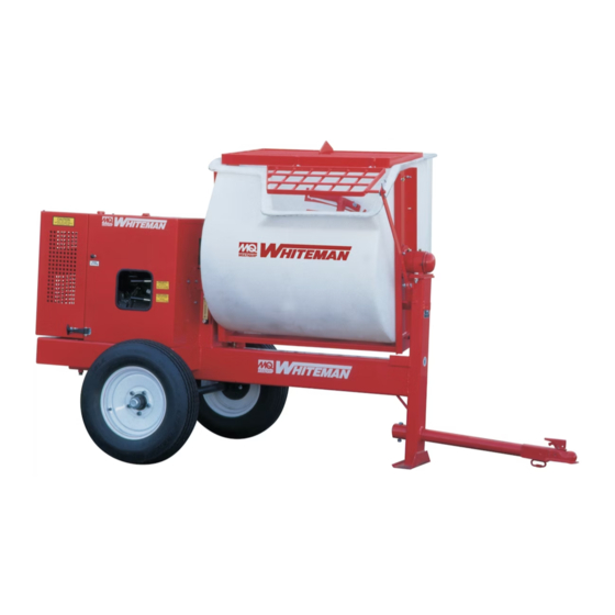
- Page 1 OPERATION AND PARTS MANUAL SERIES WM120PH Series POLYETHYLENE DRUM WM120SH Series STEEL DRUM HYDRAULIC PLASTER/MORTAR MIXERS (HONDA GASOLINE ENGINE/ELECTRIC MOTOR) Revision #7 (09/15/11) www.discount-equipment.com THIS MANUAL MUST ACCOMPANY THE EQUIPMENT AT ALL TIMES.
- Page 2 One of our experienced staff members will get back to you with a quote for the right part that your machine needs. We sell worldwide for the brands: Genie, Terex, JLG, MultiQuip, Mayco, Toro/Stone, Diamond Products, Magnum, Airman, Mustang, Power Blanket, Nifty Lift, Atlas Copco,...
-
Page 3: Proposition 65 Warning
PROPOSITION 65 WARNING Engine exhaust some its constituents, and some dust created by power sanding, sawing, grinding, drillingandotherconstructionactivities contains chemicals known to the State of California to cause cancer, birth defects and other reproductive harm. Some examples of these chemicals are: Leadfromlead-basedpaints. -
Page 4: Silicosis/Respiratory Warnings
SILICOSIS/RESPIRATORY WARNINGS WARNING WARNING SILICOSIS WARNING RESPIRATORY HAZARDS Grinding/cutting/drilling of masonry, concrete, metal and Grinding/cutting/drilling of masonry, concrete, metal and other materials with silica in their composition may give other materials can generate dust, mists and fumes off dust or mists containing crystalline silica. Silica is a containing chemicals known to cause serious or fatal basic component of sand, quartz, brick clay, granite and injury or illness, such as respiratory disease, cancer,... -
Page 5: Table Of Contents
TABLE OF CONTENTS WM120PH/SH HYDRAULIC Hydraulic Assembly .......... 54-55 Frame 1 Assembly ........... 56-57 MIXER Frame 2 Assembly ........... 58-59 Proposition 65 Warning ........... 2 Frame 3 Assembly ........... 60-61 Silicosis/Respiratory Warnings ........ 3 Plastic Engine Cover Assembly ....... 62-63 Table of Contents ............ -
Page 6: Safety
SAFETY FOR YOUR SAFETY AND SAFETY OF OTHERS! HAZARD SYMBOLS Safety precautions should be followed at all Potential hazards associated with the operation of this times when operating this equipment. Failure equipment will be referenced with Hazard Symbols which to read and understand the Safety Messages appear throughout this manual, and will be referenced in and Operating Instructions could result in injury conjunction with Safety Message Alert Symbols. -
Page 7: Safety
SAFETY CAUTION — Rotating Parts Hazards CAUTION — Overspeed Conditions NEVER operate equipment with covers or NEVER tamper with the factory setting of guards removed. Keep fingers, hands, hair the engine governor. Personal injury and and clothing away from all moving parts equipment damage can result if operating to prevent injury. -
Page 8: Rules And Regulations
NEVER use accessories or attachments that are not ALWAYS store the equipment in a clean, dry location recommended by Multiquip for this equipment. Damage out of the reach of children. to the equipment and/or injury to user may result. - Page 9 Keep all inexperienced and unauthorized people away from the equipment at all times. technical questions or information recommended by Multiquip for this equipment. Damage to the equipment Unauthorized equipment modifications will void all and/or injury to user may result.
- Page 10 RULES AND REGULATIONS EMERGENCIES ALWAYS know the location of the nearest fire extinguisher . ALWAYS know the location of the nearest first aid kit . In emergencies, always know the location of the nearest phone or keep a phone on the job site . Also know the phone numbers of the nearest ambulance , doctor and fire department .
-
Page 11: Towing Guidelines
TOWING GUIDELINES ALWAYS make sure that the fuel valve lever is in the TOWING SAFETY PRECAUTIONS OFF position (gasoline models only). CAUTION — Inspect Towing Components Check wheel mounting lug nuts with a torque wrench. To reduce the possibility of an accident while transporting Torque wheel lug nuts as described in the maintenance the machine on public roads, always make sure that the section of this manual. -
Page 12: Safety Chain Connection
SAFETY CHAIN CONNECTION 2. Route the safety chain through the holes just above CAUTION — Tow With Safety Chain the tow bar, located on each side of the mixer stand. NEVER! tow the mixer with the safety chain removed. Loop the chain together and place under the tow bar. The safety chain is intended to prevent complete Secure the loop with the connector link. -
Page 13: Specifications
SPECIFICATIONS i f i o i t y t i y t i ) . g . n i i t c t f . e t i ) s r a l t ) . g . n i c i l l l a c i l... -
Page 14: Dimensions
DIMENSIONS i r c i t p . n i . n i . n i . n i Figure 2. Dimensions PAGE 14 — WM120PH/SH HYDRAULIC MIXER • OPERATION AND PARTS MANUAL — REV. #7 (09/15/11) -
Page 15: General Information
GENERAL INFORMATION Hardware Application Check all hardware on the mixer before starting. Periodically The MQ WM120 series hydraulic mixers (drum capacity inspect all hardware. Loose hardware can contribute to early 12.0 cu. ft./340 liters) are shipped completely assembled component failure and poor performance. Use Table 4 as and have been factory tested and are ready for use. -
Page 16: Mixer Components
MIXER COMPONENTS 9. Manual Dump Handle — Pull this handle downward to dump the contents of the drum. Push the handle upward to return the drum to its vertical position. This feature is not available on hydraulic dump models. 10. Safety Grill Lock Handle — To prevent injury to hands and arms, the safety grill should ALWAYS be locked when the mixing of plaster or mortar is required. -
Page 17: Hydraulic Components
MIXER COMPONENTS/HYDRAULIC COMPONENTS Figure 4. Mixer Components (Stationary) 17. Adjustable Stabilizer Jack Stands — Use these jack stands (3) to adjust the mixer to the desired height. 18. Forklift Pockets — When lifting of the mixer is required, use these fork lift pockets to lift the mixer. Remember to insert the forks of the forklift a minimum of 24 inches Figure 5. -
Page 18: Engine Components
ENGINE COMPONENTS 4. Recoil Starter (pull rope) – Manual-starting method. Pull the starter grip until resistance is felt, then pull briskly and smoothly. 5. Fuel Valve Lever – OPEN to let fuel flow, CLOSE to stop the flow of fuel. 6. -
Page 19: Electric Motor Components
ELECTRIC MOTOR COMPONENTS ELECTRIC MOTOR Electric Motor Connection For lubrication care and operation of the electric motor, The electrical motors used on these mixers are equipped refer to your electric motor instruction booklet furnished with either a 3-prong (1Ø) or a 4-prong (3Ø) plug (Figure 7) with the motor. -
Page 20: Paddle Blade Adjustment (Steel Drum)
PADDLE BLADE ADJUSTMENT (STEEL DRUM) Adjust paddles as shown in Figure 8. Figure 8. Paddle Blade Adjustment (Steel Drum) PAGE 20 — WM120PH/SH HYDRAULIC MIXER • OPERATION AND PARTS MANUAL — REV. #7 (09/15/11) -
Page 21: Paddle Blade Adjustment (Poly Drum)
PADDLE BLADE ADJUSTMENT (POLY DRUM) Adjust paddles as shown in Figure 9. Figure 9. Paddle Blade Adjustment (Poly Drum) WM120PH/SH HYDRAULIC MIXER • OPERATION AND PARTS MANUAL — REV. #7 (09/15/11) — PAGE 21... -
Page 22: Inspection
INSPECTION This section is intended to assist the operator with the inspection of the hydraulic mixer. It is extremely important that this section be read carefully before attempting to use Reference manufacturer engine manual for the mixer in the field. specific servicing instructions. - Page 23 INSPECTION HYDRAULIC OIL Check hydraulic oil sight gauge (Figure 12) to ensure that hydraulic oil is at the midway level. Figure 12. Hydraulic Oil Sight Gauge HYDRAULIC HOSES Figure 14. Grease Fittings (Dump Cylinder) Check hydraulic hoses to make sure they are not worn, BLADE CHECK frayed or defective.
-
Page 24: Initial Start-Up (Gasoline)
INITIAL START-UP (GASOLINE) Place the engine ON/OFF switch (Figure 19) in the ON STARTING THE ENGINE position position. The following steps outline the procedure for starting the engine. Depending on the type of engine employed in the mixer the steps may vary slightly. If your mixer has an electric motor disregard this section. -
Page 25: Initial Start-Up (Electric)
INITIAL START-UP (ELECTRIC)/OPERATION STARTING THE ELECTRIC MOTOR 1. Using an adequate size extension cord (Table 7), connect one end of the extension cord to the plug on the electric motor, connect the other end to the power source. Make sure the motor is configured for the proper operating voltage. -
Page 26: Operation
OPERATION DUMPING (MANUAL) DUMPING (HYDRAULIC) 1. Release drum lock lever by pushing lever into vertical 1. If operating a mixer with hydraulic dump capability, pull position (Figure 25). hydraulic dump lever (Figure 27) outward to place drum in dump position (Figure 28). Figure 25. -
Page 27: Shut-Down
SHUT-DOWN STOPPING THE MIXER (GASOLINE ENGINE) STOPPING THE MIXER (ELECTRIC MOTOR) 1. Push the start/stop switch (Figure 29) inward to stop 1. To stop the electric motor, press the red OFF/STOP the engine. switch (Figure 31). STOP START PRESS TO STOP Figure 31. -
Page 28: Maintenance (Engine)
MAINTENANCE (ENGINE) Use Table 8 as a general maintenance guideline when servicing your engine. For more detail engine maintenance information, refer to the engine owner's manual supplied with your engine. ) 3 ( l i O r i A ) 1 ( g i t l l A &... - Page 29 MAINTENANCE (ENGINE) 3. Replace engine oil with recommended type oil as listed MAINTENANCE in Table 6. For engine oil capacity, see Table 2 (engine Perform the scheduled maintenance procedures as defined specifications). DO NOT overfill. by Table 8 and below: 4.
-
Page 30: Maintenance (Mixer)
MAINTENANCE (MIXER) BALL SOCKET AND CLAMP FACE MAINTENANCE DRUM HEAD SEALS There is 1 set of drum head seals (Figure 35) that will require If the towing vechicle is equipped with a ball socket, lubrication. Lubricate the grease fitting for each drum seal smear socket periodically with multi-purpose grease. - Page 31 MAINTENANCE (MIXER) TIRES/WHEELS/LUG NUTS LUG NUT TORQUE REQUIREMENTS Tires and wheels are a very important and critical It is extremely important to apply and maintain proper wheel components of the trailer. When specifying or replacing mounting torque. Be sure to use only the fasteners matched the trailer wheels it is important the wheels, tires, and axle to the cone angle of the wheel.
- Page 32 MAINTENANCE (MIXER) 3. After first road use, retorque all lug nuts in sequence. SUSPENSION Check all wheel lug nuts periodically. The suspension type axle and associated hardware (Figure 40) should be periodically inspected for signs of excessive wear, elongation of bolt holes, and loosening of fasteners. Replace all damaged parts immediately.
-
Page 33: Storage
MAINTENANCE (MIXER)/STORAGE 9. NEVER! pour or spray water over the engine or electric MIXER STORAGE motor (Figure 41). For storage of the mixer for over 30 days, the following is recommended: Drain the fuel tank completely, or add STA-BIL to the fuel. -
Page 34: Troubleshooting (Engine)
TROUBLESHOOTING (ENGINE) Practically all breakdowns can be prevented by proper handling and maintenance inspections, but in the event of a breakdown, please take a remedial action following the diagnosis based on the Engine , Mixer and Electric Motor Troubleshooting (Tables 11,12, and 13) information shown below and on the proceeding pages. If the problem cannot be remedied, please leave the unit just as it is and consult or company's service department. - Page 35 TROUBLESHOOTING (ENGINE) f l a i t c i l o i l o c i f " " n r i A a t - l i f r e t r i a a t - t l i f .
-
Page 36: Troubleshooting (Mixer/Electric Motor)
TROUBLESHOOTING (MIXER/ELECTRIC MOTOR) a i r , y v a i r e x i e x i t i l i i s n i x i . s t r t s o i t o i t e r r f e i l e v l... -
Page 37: Wiring Diagram (Electric Motor)
WIRING DIAGRAM (ELECTRIC MOTOR) WHITE/NEUTRAL 230 VAC 1Ø 2-POLE/3-WIRE GROUNDING BLACK/LINE GREEN/GROUND L6-30P TWIST-LOCK SINGLE OR THREE PHASE L6-30P/L1620P ELECTRIC MOTOR TWIST-LOCK PIGTAIL END ELECTRIC CABLE WHITE/NEUTRAL 460 VAC 3Ø 3-POLE/4-WIRE GROUNDING BLACK/LINE GREEN/GROUND RED/LINE L16-20P TWIST-LOCK Figure 43. Electric Motor Wiring Diagram WM120PH/SH HYDRAULIC MIXER •... -
Page 38: Hydraulic System Diagram
HYDRAULIC SYSTEM DIAGRAM HYDRAULIC SYSTEM DIAGRAM HYDRAULIC FORWARD/REVERSE DUMP GEAR POWER PUMP RELIEF VALVE 1750 PSI RETURN SUCTION FILTER STRAINER BYPASS 25 PSI MOTOR TANK TANK RELIEF CYLINDER VALVE 1750 PSI SHOWN WITH OPTIONAL HYDRAULIC DUMP Figure 44. Hydraulic System Diagram PAGE 38 —... -
Page 39: Explanation Of Code In Remarks Column
A blank entry generally indicates that the item is not sold assembly/kit that can be purchased, or is not available separately or is not sold by Multiquip. Other entries will for sale through Multiquip. be clarified in the “Remarks” Column. -
Page 40: Suggested Spare Parts
SUGGESTED SPARE PARTS WM120PS 1 TO 3 UNITS WM120PS 5 TO 10 UNITS Qty. Description Qty. Description 6 .... 491010 .... RUBBER LATCH ASSY. 10 ..491010 .... RUBBER LATCH ASSY. 1 .... EM200293A ..PADDLE ARM TOW SIDE 2 .... EM200293A ..PADDLE ARM TOW SIDE 1 .... -
Page 41: Nameplate And Decals
NAMEPLATE AND DECALS PAGE 42 — WM120PH/SH HYDRAULIC MIXER • OPERATION AND PARTS MANUAL — REV. #7 (09/15/11) - Page 42 NAMEPLATE AND DECALS PART NO. PART NAME QTY. REMARKS DCL151 DECAL, TOWING INSTRUCTIONS EM948630 DECAL, PUSH TO STOP DCL160A DECAL, CRUSH WARNING 515275 DECAL, WHITEMAN LOGO (SMALL) 504713 DECAL, SAFETY INSTRUCTIONS 35137 DECAL, WARNING READ 504714 DECAL, WHITEMAN LOGO (LARGE) 513479 DECAL, WARNING SAFETY GRATE DCL335...
- Page 43 PADDLE BLADES ASSY. ENGINE END CENTER ENGINE END CENTER TOW END WIPER SCRAPPER HARDWARE PAGE 44 — WM120PH/SH HYDRAULIC MIXER • OPERATION AND PARTS MANUAL — REV. #7 (09/15/11)
-
Page 44: Paddle Blades Assembly
PADDLE BLADES ASSY. PART NO. PART NAME QTY. REMARKS 492584 NUT, LOCK 1/2" EM200295A PADDLE ARM, CENTER TOW END EM200292 INSERT, PADDLE ARM EM200293A PADDLE ARM, TOW END 6109170 WASHER, FLAT 1/2" EM200297 U-BOLT, END PADDLES EM200294A PADDLE ARM, CENTER ENGINE END 492366 SCREW, HHC 5/16-18 X 1-1/2 G5 EM923023... - Page 45 PLASTIC MIXING DRUM ASSY. PAGE 46 — WM120PH/SH HYDRAULIC MIXER • OPERATION AND PARTS MANUAL — REV. #7 (09/15/11)
-
Page 46: Plastic Mixing Drum Assembly
PLASTIC MIXING DRUM ASSY. PART NO PART NAME QTY. REMARKS 3309 GRATE, MOVABLE EM963057 HHCS 3/8 X 1-1/2" 13270 GRATE, STATIONARY EM969013 NUT, NYLOC 3/8-16 6109170 WASHER, FLAT 1/2" .......... 2 .... MANUAL DUMP ONLY 504943 SCREW, FLATHEAD 3/8" NC X 2 3006 SUPPORT DISK 507719... - Page 47 STEEL DRUM ASSY. (MANUAL) PAGE 48 — WM120PH/SH HYDRAULIC MIXER • OPERATION AND PARTS MANUAL — REV. #7 (09/15/11)
-
Page 48: Steel Drum Assembly (Manual)
STEEL DRUM ASSY. (MANUAL) PART NO PART NAME QTY. REMARKS EM203449 GRATE, MOVABLE 7170 5/32" 3-5/16" 6109170 WASHER, FLAT 1/2" 13276 BAR, GRATE LATCH EM969013 NUT, NYLOC 3/8" EM621 WASHER, FLAT 1/2" SPECIAL 491008 CAP, GREASE FITTING EM916019 GREASE FITTING EM963105 SCREW, HHCS 1/2"... - Page 49 STEEL DRUM ASSY. (HYDRAULIC) L I C NOTES: COMPLETE DRUM ASSEMBLY, ITEM 27 INCLUDES ITEMS WITHIN DASHED LINE. ALSO INCLUDED ARE PART OF FRAME PADDLE SHAFT AND PADDLE ARMS. SEE PADDLE SHAFT AND PADDLE ARM ASSEMBLIES IN THIS MANUAL. PAGE 50 — WM120PH/SH HYDRAULIC MIXER • OPERATION AND PARTS MANUAL — REV. #7 (09/15/11)
-
Page 50: Steel Drum Assembly (Hydraulic)
STEEL DRUM ASSY. (HYDRAULIC) PART NO PART NAME QTY. REMARKS EM203449 MOVEABLE GRATE 7170 PIN, HITCH CLIP 5/32" 3-5/16" 6109170 WASHER, FLAT 1/2" 13276 BAR, GRATE EM969013 NUT, NYLOC 3/8" EM621 WASHER, FLAT 1/2" SPECIAL 491008 CAP, GREASE FITTING EM916019 GREASE FITTING EM963105 SCREW, HHCS 1/2"... - Page 51 PADDLE SHAFT ASSY. (PLASTIC/STEEL) STYLE PADDLE SHAFT SEAL KIT ENGINE NOTES: OLD STYLE PADDLE SHAFTS P/N 13257 (STEEL DRUM), P/N13282 (PLASTIC DRUM) NO LONGER AVAILABLE. SEE NOTE 2 WHEN RE-ORDERING PADDLE SHAFTS. PADDLE SHAFT KITS P/N 514234K (PLASTIC DRUM), P/N 514233K (STEEL DRUM) INCLUDES ITEMS 15A, 16A, 17 AND 18.
-
Page 52: Paddle Shaft Assembly (Plastic/Steel)
PADDLE SHAFT ASSY. (PLASTIC/STEEL) PART NO PART NAME QTY. REMARKS 3061 SPACER, THIN SEAL 3494 OUTER SEAL, URETHANE 1-1/4 OD 3019 INNER SEAL 1-1/8" 3024 SPRING 13002 SEAL, BEARING 1-1/2" EM902153 BEARING 13274 SPACER 3347 NUT, SPECIAL 1-1/2"-12 13108 WASHER, FLAT USS 1-1/8" 10176 NUT, NYLOC 1/2-13 ........ - Page 53 HYDRAULIC ASSY. PAGE 54 — WM120PH/SH HYDRAULIC MIXER • OPERATION AND PARTS MANUAL — REV. #7 (09/15/11)
-
Page 54: Hydraulic Assembly
HYDRAULIC ASSY. PART NO. PART NAME QTY. REMARKS 492356 BOLT 1/4" X 3/4" 2101402 WASHER, SPRING 1/4" .......... 2 ....REPLACES 492622 EM969013 NUT, NYLOCK ............1 ....REPLACES 492583 3019092 WASHER 3/8" FLAT ..........2 ....REPLACES 492598 492584 NUT, LOCK 1/2"... - Page 55 FRAME 1 ASSY. 4 LUG HUB AND WHEEL (1-1/16 AXLE SPINDLE) S/N KA26943 T0 HD27963 JANUARY 1996 — APRIL 1999 PAGE 56 — WM120PH/SH HYDRAULIC MIXER • OPERATION AND PARTS MANUAL — REV. #7 (09/15/11)
-
Page 56: Frame 1 Assembly
FRAME 1 ASSY. 4 LUG HUB AND WHEEL (1-1/16 AXLE SPINDLE) S/N KA26943 T0 HD27963 JANUARY 1996 — APRIL 1999 PART NO PART NAME QTY. REMARK 13212 GROMMET ..........1 .... WITH DUMP (HYDRAULIC DUMP CYL.) 29194 LUG NUT........... 8 .... REPLACES 8115 13120 MAIN FRAME ...........1 .... - Page 57 FRAME 2 ASSY. 5 LUG HUB AND WHEEL (1-1/16 AXLE SPINDLE) S/N HD27964 T0 GE210000 APRIL 1999 — MAY 2000 PAGE 58 — WM120PH/SH HYDRAULIC MIXER • OPERATION AND PARTS MANUAL — REV. #7 (09/15/11)
-
Page 58: Frame 2 Assembly
FRAME 2 ASSY. 5 LUG HUB AND WHEEL (1-1/16 AXLE SPINDLE) S/N HD27964 T0 GE210000 APRIL 1999 — MAY 2000 PART NO PART NAME QTY. REMARK 13212 GROMMET ..........1 .... WITH DUMP (HYDRAULIC DUMP CYL.) 13120 MAIN FRAME ...........1 .... S/N KA26943 TO II27769 13365 MAIN FRAME ...........1 .... - Page 59 FRAME 3 ASSY. 5 LUG HUB AND WHEEL (1-1/16 AXLE SPINDLE) S/N GE21000 AND ABOVE MAY 2000 AND ABOVE PAGE 60 — WM120PH/SH HYDRAULIC MIXER • OPERATION AND PARTS MANUAL — REV. #7 (09/15/11)
-
Page 60: Frame 3 Assembly
FRAME 3 ASSY. 5 LUG HUB AND WHEEL (1-1/16 AXLE SPINDLE) S/N GE21000 AND ABOVE MAY 2000 AND ABOVE PART NO PART NAME QTY. REMARK 13212 GROMMET ..........1 ..... WITH DUMP (HYDRAULIC DUMP CYL.) EM941280 LUG NUT 13120 MAIN FRAME ......... 1 ..... S/N KA26943 TO II27769 ................. - Page 61 PLASTIC ENGINE COVER ASSY. S/N KA26943 TO GE 210000 JANUARY 1996 TO MAY 2000 PAGE 62 — WM120PH/SH HYDRAULIC MIXER • OPERATION AND PARTS MANUAL — REV. #7 (09/15/11)
-
Page 62: Plastic Engine Cover Assembly
PLASTIC ENGINE COVER ASSY. S/N KA26943 TO GE 210000 JANUARY 1996 TO MAY 2000 PART NO PART NAME QTY. REMARK 13221 ENGINE COVER ASSY. - PLASTIC ONLY ..1 ... S/N KA26943 TO GE210000 3089 HINGE PIN 8151 FLAT WASHER 3/4" 0183 COTTER PIN 3163... - Page 63 STEEL ENGINE COVER ASSY. GE 210001 AND ABOVE MAY 2000 AND ABOVE PAGE 64 — WM120PH/SH HYDRAULIC MIXER • OPERATION AND PARTS MANUAL — REV. #7 (09/15/11)
-
Page 64: Steel Engine Cover Assembly
STEEL ENGINE COVER ASSY. GE 210001 AND ABOVE MAY 2000 AND ABOVE PART NO. PART NAME QTY. REMARKS 511580 ENGINE COVER-STEEL ........1 ..S/N GE210001 AND ABOVE 509726 HINGE 491010 RUBBER LATCH ASSY. 1284 SCREW, HHCS 3/8-16 X 1-1/2" 4001 FLAT WASHER 3/8"... - Page 65 SINGLE PHASE, 5 HP ELECTRIC MOTOR ASSY. PAGE 66 — WM120PH/SH HYDRAULIC MIXER • OPERATION AND PARTS MANUAL — REV. #7 (09/15/11)
-
Page 66: Single Phase, 5 Hp Electric Motor Assembly
SINGLE PHASE, 5 HP ELECTRIC MOTOR ASSY. PART NO. PART NAME QTY. REMARKS 0166 A WASHER, LOCK 3/8 MED........2....REPLACES 492624 EM963610 CAPSCREW 3/8" NCX1-1/4" G8 ......6....REPLACES 492375 492581 NUT 1/4" - 20 NYLON LOCKNUT EM963610 CAPSCREW 3/8"... - Page 67 THREE PHASE, 5 HP ELECTRIC MOTOR ASSY. PAGE 68 — WM120PH/SH HYDRAULIC MIXER • OPERATION AND PARTS MANUAL — REV. #7 (09/15/11)
-
Page 68: Three Phase, 5 Hp Electric Motor Assembly
THREE PHASE, 5 HP ELECTRIC MOTOR ASSY. PART NO. PART NAME QTY. REMARKS 0166 A WASHER, LOCK 3/8 MED........10....REPLACES 492624 EM963610 CAPSCREW 3/8" NCX1-1/4" G8 ......2....REPLACES 492375 492581 NUT 1/4" - 20 NYLON LOCKNUT EM963610 CAPSCREW 3/8"... - Page 69 HONDA ENGINE ASSY. PAGE 70 — WM120PH/SH HYDRAULIC MIXER • OPERATION AND PARTS MANUAL — REV. #7 (09/15/11)
-
Page 70: Honda Engine Assembly
HONDA ENGINE ASSY. PART NO. PART NAME QTY. REMARKS 3364 ENGINE, HONDA 13HP GX390U1QA2 203148 TUBE, EXHAUST 203123F PLATE 491797 RIVET, ID PLATE 29174-001 KNOB-MUSHROOM 29173-001 SWITCH, PUSH-PULL W/O KNOB 0310 KEY 1/4 SQUARE 1-1/2 492379 SCREW CAP 3/8" 3019092 WASHER 3/8"... -
Page 71: Honda Gx390K1Qa2
HONDA GX390K1QA2/GX390U1QA2 — AIR CLEANER ASSY. PAGE 72 — WM120PH/SH HYDRAULIC MIXER • OPERATION AND PARTS MANUAL — REV. #7 (09/15/11) -
Page 72: Air Cleaner Assembly
HONDA GX390K1QA2/GX390U1QA2 — AIR CLEANER ASSY. PART NO. PART NAME QTY. REMARKS 16271ZE2000 GASKET, ELBOW 17210ZE3010 ELEMENT, AIR CLEANER ....1 ..INCLUDES ITEMS W/ # 17218ZE3000 FILTER, OUTER 17231ZE3W01 COVER, AIR CLEANER 17232891000 GROMMET, AIR CLEANER 6 17235ZH9N00 NOSE, SILENCER 6◊... - Page 73 HONDA GX390K1QA2/GX390U1QA2 — CAMSHAFT ASSY. PAGE 74 — WM120PH/SH HYDRAULIC MIXER • OPERATION AND PARTS MANUAL — REV. #7 (09/15/11)
-
Page 74: Camshaft Assembly
HONDA GX390K1QA2/GX390U1QA2 — CAMSHAFT ASSY. PART NO. PART NAME QTY. REMARKS 1 14100ZF6W0 CAMSHAFT ASSEMBLY ....... 1 ....INCLUDES ITEMS W/ ..................SN 2391939 AND BELOW 1 14100ZF6W01 CAMSHAFT ASSEMBLY ....... 1 ....INCLUDES ITEMS W/ .................. - Page 75 HONDA GX390K1QA2/GX390U1QA2 — PISTON ASSY. PAGE 76 — WM120PH/SH HYDRAULIC MIXER • OPERATION AND PARTS MANUAL — REV. #7 (09/15/11)
-
Page 76: Piston Assembly
HONDA GX390K1QA2/GX390U1QA2 — PISTON ASSY. NO. PART NO. PART NAME QTY. REMARKS 13010ZF6003 RING SET, PISTON (STD.) 13010ZF6005 RING SET, PISTON (STD.) 13011ZF6003 RING SET, PISTON (OS 0.25), OPT. 13011ZF6005 RING SET, PISTON (OS 0.25), OPT. 13012ZF6003 RING SET, PISTON (OS 0.50), OPT. 13012ZF6005 RING SET, PISTON (OS 0.50), OPT. - Page 77 HONDA GX390K1QA2/GX390U1QA2 — CRANKCASE COVER ASSY. PAGE 78 — WM120PH/SH HYDRAULIC MIXER • OPERATION AND PARTS MANUAL — REV. #7 (09/15/11)
-
Page 78: Crankcase Cover Assembly
HONDA GX390K1QA2/GX390U1QA2 — CRANKCASE COVER ASSY. PART NO. PART NAME QTY. REMARKS 06165ZE3000 GOVERNOR KIT (OPIONAL) ......1 ..INCLUDES ITEMS W/ # 2 11300ZE3602 COVER ASSY., CRANKCASE (Q TYPE) ..1 ..INCLUDES ITEMS W/ .................. - Page 79 HONDA GX390K1QA2/GX390U1QA2 — CRANKSHAFT ASSY. PAGE 80 — WM120PH/SH HYDRAULIC MIXER • OPERATION AND PARTS MANUAL — REV. #7 (09/15/11)
-
Page 80: Crankshaft Assembly
HONDA GX390K1QA2/GX390U1QA2 — CRANKSHAFT ASSY. PART NO. PART NAME QTY. REMARKS 2 13310ZF6W10 CRANKSHAFT, Q-TYPE ........1 ..INCLUDES ITEMS W/ 2◊ ◊ ◊ ◊ ◊ 13310ZF6W11 CRANKSHAFT COMP........1 ..S/N 1113739 AND BELOW 2◊... - Page 81 HONDA GX390K1QA2/GX390U1QA2 — CYLINDER BARREL ASSY. PAGE 82 — WM120PH/SH HYDRAULIC MIXER • OPERATION AND PARTS MANUAL — REV. #7 (09/15/11)
-
Page 82: Cylinder Barrel Assembly
HONDA GX390K1QA2/GX390U1QA2 — CYLINDER BARREL ASSY. PART NO. PART NAME QTY. REMARKS 1 12000ZF6W12 BARREL ASSY., CYL. ALERT OIL ..1..INCLUDES ITEMS W/ ................SN 3020570 AND BELOW 1 12000ZF6W13 BARREL ASSY., CYL. ALERT OIL ..1..INCLUDES ITEMS W/ ................ - Page 83 HONDA GX390K1QA2/GX390U1QA2 — CYLINDER HEAD ASSY. PAGE 84 — WM120PH/SH HYDRAULIC MIXER • OPERATION AND PARTS MANUAL — REV. #7 (09/15/11)
-
Page 84: Cylinder Head Assembly
HONDA GX390K1QA2/GX390U1QA2 — CYLINDER HEAD ASSY. PART NO. PART NAME QTY. REMARKS 1 12200ZF6W01 CYLINDER HEAD ..........1 ..INCLUDES ITEMS W/ 1◊ ◊ ◊ ◊ ◊ 12200ZF6406 CYLINDER HEAD ..........1 ..INCLUDES ITEMS W/ 12204ZE2306 GUIDE, VALVE OS (OPTIONAL) 12205ZE2305... - Page 85 HONDA GX390K1QA2/GX390U1QA2 — FAN COVER ASSY. PAGE 86 — WM120PH/SH HYDRAULIC MIXER • OPERATION AND PARTS MANUAL — REV. #7 (09/15/11)
-
Page 86: Fan Cover Assembly
HONDA GX390K1QA2/GX390U1QA2 — FAN COVER ASSY. PART NO. PART NAME QTY. REMARKS 16731ZE2003 CLIP, TUBE 19610ZE3010ZA COVER, FAN *R280*, RED 19631ZE3W00 SHROUD 4 32197ZH8003 SUB-HARNESS ........... 1 ..SN 2334667 AND BELOW 5 36100ZE1015 SWITCH ASSY., ENGINE STOP .... - Page 87 HONDA GX390K1QA2/GX390U1QA2 — FLYWHEEL ASSY. PAGE 88 — WM120PH/SH HYDRAULIC MIXER • OPERATION AND PARTS MANUAL — REV. #7 (09/15/11)
-
Page 88: Flywheel Assembly
HONDA GX390K1QA2/GX390U1QA2 — FLYWHEEL ASSY. PART NO. PART NAME QTY. REMARKS 19511ZE3000 FAN, COOLING 28450ZE3W11 PULLEY, STARTER (SCREEN GRID) 31100ZE3701 FLYWHEEL 6 90201ZE3790 NUT, SPECIAL 16MM ........1 ..S/N 2263434 AND BELOW 6 90201ZE3V00 NUT, SPECIAL 16MM (1) ...... - Page 89 HONDA GX390K1QA2/GX390U1QA2 — IGNITION COIL ASSY. PAGE 90 — WM120PH/SH HYDRAULIC MIXER • OPERATION AND PARTS MANUAL — REV. #7 (09/15/11)
-
Page 90: Ignition Coil Assembly
HONDA GX390K1QA2/GX390U1QA2 — IGNITION COIL ASSY. PART NO. PART NAME QTY. REMARKS 1 30500ZF6W02 COIL ASSEMBLY, IGNITION ....... 1 ..REPLACES 305007E2023 1◊ ◊ ◊ ◊ ◊ 30500ZF6W02 COIL ASSEMBLY, IGNITION ....... 1 ..S/N 1411816 AND BELOW 1◊... - Page 91 HONDA GX390K1QA2/GX390U1QA2 — CARBURETOR ASSY. PAGE 92 — WM120PH/SH HYDRAULIC MIXER • OPERATION AND PARTS MANUAL — REV. #7 (09/15/11)
-
Page 92: Carburetor Assembly
HONDA GX390K1QA2/GX390U1QA2 — CARBURETOR ASSY. CARBURETOR ASSY. PART NO. PART NAME QTY. REMARKS 1 #% 16010ZE2812 GASKET SET ..........1 ..INCLUDES ITEM W/& 16011ZA0931 VALVE SET, FLOAT 16013ZA0931 FLOAT SET 4 16015ZE2005 CHAMBER SET, FLOAT ......1 ..INCLUDES ITEMS W/ % .................. - Page 93 HONDA GX390K1QA2/GX390U1QA2 — MUFFLER ASSY. PAGE 94 — WM120PH/SH HYDRAULIC MIXER • OPERATION AND PARTS MANUAL — REV. #7 (09/15/11)
-
Page 94: Muffler Assembly
HONDA GX390K1QA2/GX390U1QA2 — MUFFLER ASSY. PART NO. PART NAME QTY. REMARKS 18310ZE2W61 MUFFLER 100DB 18320ZE2W61 PROTECTOR, MUFFLER 18323ZE3W40 PROTECTOR, EXHAUST PIPE 18330ZE2W00 PIPE, EXHAUST 5 18331ZE3810 CAP, MUFFLER 5◊ ◊ ◊ ◊ ◊ 18331ZE3810 CAP, MUFFLER ........... 1 ..S/N 1166160 AND BELOW 5◊... - Page 95 HONDA GX390K1QA2/GX390U1QA2 — RECOIL STARTER ASSY. PAGE 96 — WM120PH/SH HYDRAULIC MIXER • OPERATION AND PARTS MANUAL — REV. #7 (09/15/11)
-
Page 96: Recoil Starter Assembly
HONDA GX390K1QA2/GX390U1QA2 — RECOIL STARTER ASSY. PART NO. PART NAME QTY. REMARKS 1 28400ZE3W01ZA STARTER ASSY., RECOIL *R8*, RED....1 ..INCLUDES ITEMS W/ 1◊ ◊ ◊ ◊ ◊ 28400ZE3W01ZP STARTER ASSY., RECOIL *R280*, RED..1 ..INCLUDES ITEMS W/ 2... - Page 97 HONDA GX390K1QA2/GX390U1QA2— CONTROL ASSY. PAGE 98 — WM120PH/SH HYDRAULIC MIXER • OPERATION AND PARTS MANUAL — REV. #7 (09/15/11)
-
Page 98: Control Assembly
HONDA GX390K1QA2/GX390U1QA2— CONTROL ASSY. PART NO. PART NAME QTY. REMARKS 16551ZE3000 ARM, GOVERNOR 16555ZE3000 ROD, GOVERNOR 16561ZE3000 SPRING, GOVERNOR 16562ZE3000 SPRING, THROTTLE RETURN 16570ZE3W20 CONTROL ASSEMBLY, REMOTE ....1 ..INCLUDES ITEMS W/ 16571ZE3W00 LEVER, CONTROL 16574ZE1000 SPRING, LEVER 1675ZE2W00 WASHER, CONTROL LEVER 16576891000 HOLDER, CABLE... - Page 99 HONDA GX390K1QA2/GX390U1QA2 — FUEL TANK ASSY. PAGE 100 — WM120PH/SH HYDRAULIC MIXER • OPERATION AND PARTS MANUAL — REV. #7 (09/15/11)
-
Page 100: Fuel Tank Assembly
HONDA GX390K1QA2/GX390U1QA2 — FUEL TANK ASSY. PART NO. PART NAME QTY. REMARKS 16854ZH8000 RUBBER, SUPPORTER (107MM) 16955ZE1000 JOINT, FUEL TANK 6 17510ZE3010ZA TANK, FUEL *NH31* 6 17510ZE3010ZB TANK, FUEL *NH1* 6 17510ZE3010ZA TANK, FUEL *T34* 6◊... - Page 101 HONDA GX390K1QA2 — GASKET KIT ASSY. PAGE 102 — WM120PH/SH HYDRAULIC MIXER • OPERATION AND PARTS MANUAL — REV. #7 (09/15/11)
-
Page 102: Gasket Kit Assembly
HONDA GX390K1QA2 — GASKET KIT ASSY. PART NO. PART NAME QTY. REMARKS 11381ZE3800 GASKET, CASE COVER 12251ZF6W00 GASKET, CYLINDER HEAD 12391ZE2020 GASKET, CYLINDER HEAD COVER 16221ZF6800 GASKET, CARBURETOR 16223ZE3W00 GASKET, INSULATOR 18333ZF6W01 GASKET, EXHAUST PIPE 18381ZE2W10 GASKET, MUFFLER (ARRESTER) 061A1Z6700 GASKET KIT .......... - Page 103 HONDA GX390K1QA2/GX390U1QA2 — LABELS ASSY. GX-390K1QA2 GX-390U1QA2 PAGE 104 — WM120PH/SH HYDRAULIC MIXER • OPERATION AND PARTS MANUAL — REV. #7 (09/15/11)
-
Page 104: Labels Assembly
HONDA GX390K1QA2/GX390U1QA2 — LABELS ASSY. PART NO. PART NAME QTY. REMARKS 1◊ ◊ ◊ ◊ ◊ 87516ZH7000 MARK, OPERATOR 3◊ ◊ ◊ ◊ ◊ 87532ZH7000 MARK,, THROTTLE INDICATION 4 87521ZF6W01 EMBLEM ..........1 ..... S/N 3249629 AND BELOW 4... - Page 105 One of our experienced staff members will get back to you with a quote for the right part that your machine needs. We sell worldwide for the brands: Genie, Terex, JLG, MultiQuip, Mayco, Toro/Stone, Diamond Products, Magnum, Airman, Mustang, Power Blanket, Nifty Lift, Atlas Copco,...