
Related Manuals for MULTIQUIP WTB-16PD


Summary of Contents for MULTIQUIP WTB-16PD
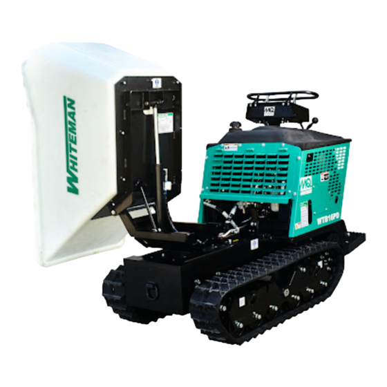
- Page 1 OPERATION MANUAL SERIES MODEL WTB-16PD TRACK-DRIVE POWER BUGGY (HONDA GX690RHKXA ELECTRIC START GASOLINE ENGINE) Revision #0 (08/31/20) THIS MANUAL MUST ACCOMPANY THE EQUIPMENT AT ALL TIMES.
- Page 2 @ www.discount-equipment.com Select an option below to find your Equipment We sell worldwide for the brands: Genie, Terex, JLG, MultiQuip, Mikasa, Essick, Whiteman, Mayco, Toro Stone, Diamond Products, Generac Magnum, Airman, Haulotte, Barreto, Power Blanket, Nifty Lift, Atlas Copco, Chicago Pneumatic, Allmand, Miller Curber, Skyjack, Lull,...
-
Page 3: Proposition 65 Warning
PROPOSITION 65 WARNING PAGE 2 — WTB-16PD TRACK-DRIVE POWER BUGGY • OPERATION MANUAL — REV. #0 (08/31/20) -
Page 4: Table Of Contents
Hydraulic Hose Connections 1 ......46 Hydraulic Hose Connections 2 ......47 Hydraulic Hose Connections 3 ......48 Electrical Component Locator Diagram ....49 Electrical Wiring Diagram ........ 50–51 WTB-16PD TRACK-DRIVE POWER BUGGY • OPERATION MANUAL — REV. #0 (08/31/20) — PAGE 3... -
Page 5: Safety Information
Indicates a hazardous situation which, if not avoided, before performing maintenance. COULD result in MINOR or MODERATE INJURY. NOTICE Addresses practices not related to personal injury. PAGE 4 — WTB-16PD TRACK-DRIVE POWER BUGGY • OPERATION MANUAL — REV. #0 (08/31/20) - Page 6 „ No one other than the operator is to be in the working area when the equipment is in operation. „ DO NOT use the equipment for any purpose other than its intended purposes or applications. WTB-16PD TRACK-DRIVE POWER BUGGY • OPERATION MANUAL — REV. #0 (08/31/20) — PAGE 5...
- Page 7 „ DO NOT stand on the power buggy step plate (platform) when walking in rough terrain. Walk behind the power buggy. PAGE 6 — WTB-16PD TRACK-DRIVE POWER BUGGY • OPERATION MANUAL — REV. #0 (08/31/20)
- Page 8 „ ALWAYS place the fuel valve lever in the OFF position capacity of power buggy. when the equipment is not in use. „ ALWAYS be aware of traveling conditions. Reduce load if necessary. WTB-16PD TRACK-DRIVE POWER BUGGY • OPERATION MANUAL — REV. #0 (08/31/20) — PAGE 7...
- Page 9 „ ALWAYS use manufacturer’s recommended parts. Unspecifi ed parts will shorten the life span of the rubber track. „ Use the rubber track for the prescribed purposes only. PAGE 8 — WTB-16PD TRACK-DRIVE POWER BUGGY • OPERATION MANUAL — REV. #0 (08/31/20)
- Page 10 „ NEVER tamper with the factory settings of the engine or engine governor. Damage to the engine or equipment can result if operating in speed ranges above the maximum allowable. WTB-16PD TRACK-DRIVE POWER BUGGY • OPERATION MANUAL — REV. #0 (08/31/20) — PAGE 9...
- Page 11 „ ALWAYS keep battery cables in good working condition. the truck and ramp capacities. Repair or replace all worn cables. „ ALWAYS place the fuel valve lever in the OFF position before transporting. PAGE 10 — WTB-16PD TRACK-DRIVE POWER BUGGY • OPERATION MANUAL — REV. #0 (08/31/20)
- Page 12 The label must remain with the engine for its entire life. If a replacement emission label is needed, please contact your authorized engine distributor. WTB-16PD TRACK-DRIVE POWER BUGGY • OPERATION MANUAL — REV. #0 (08/31/20) — PAGE 11...
-
Page 13: Specifications (Track Buggy)
Battery (L × W × H) 7.75 × 5.18 × 7.31 in. (197 × 132 × 186 mm) 5.7 × 8.0 Rubber Track (145 × 203 × 483 mm) PAGE 12 — WTB-16PD TRACK-DRIVE POWER BUGGY • OPERATION MANUAL — REV. #0 (08/31/20) -
Page 14: Noise And Vibration/Engine Specifications
0.70–0.80 mm (0.028–0.031 in.) L × W × H 405 × 410 × 438 mm (15.9 × 16.1 × 17.2 in.) Weight (Dry) 44.4 kg (97.8 lb.) WTB-16PD TRACK-DRIVE POWER BUGGY • OPERATION MANUAL — REV. #0 (08/31/20) — PAGE 13... -
Page 15: Dimensions
102.30 (2,598) 55.60 (1,412) 48.10 (1,222) 55.90 (1,420) 51.50 (1,307) 15.00 (380) 110.25 (2,800) 55.70 (1,415) 72.05 (1,830) 20.30 (515) 35.60 (905) 37.90 (963) 35.6 (905) PAGE 14 — WTB-16PD TRACK-DRIVE POWER BUGGY • OPERATION MANUAL — REV. #0 (08/31/20) -
Page 16: General Information
Safety Information, is required. General Information, and Inspection sections of this manual have been read and thoroughly understood. WTB-16PD TRACK-DRIVE POWER BUGGY • OPERATION MANUAL — REV. #0 (08/31/20) — PAGE 15... -
Page 17: Lifting And Transporting
Figure 2B. the tub loaded with material. DUMP POSITION FORKLIFT WTB16 LIFTING POINT (2) TIE-DOWN POINT (4) FLATBED TRUCK Figure 2. Lifting the Track Buggy PAGE 16 — WTB-16PD TRACK-DRIVE POWER BUGGY • OPERATION MANUAL — REV. #0 (08/31/20) - Page 18 BUGGY COMPONENTS Figure 3. WTB-16PD Power Buggy Components 1 PAGE 18 — WTB-16PD TRACK-DRIVE POWER BUGGY • OPERATION MANUAL — REV. #0 (08/31/20)
- Page 19 Operation, Parts and Engine manuals in this container in free-wheel mode before towing, otherwise damage at all times. to drive motors will occur. DO NOT tow on public roads WTB-16PD TRACK-DRIVE POWER BUGGY • OPERATION MANUAL — REV. #0 (08/31/20) — PAGE 19...
- Page 20 BUGGY COMPONENTS CONT'D. Figure 4. WTB-16PD Power Buggy Components 2 PAGE 20 — WTB-16PD TRACK-DRIVE POWER BUGGY • OPERATION MANUAL — REV. #0 (08/31/20)
- Page 21 Remove the access cover to clean out the hydraulic oil reservoir. 36. Tie-Down Hook — When transporting of the buggy is required, attach a strap to these tie-down points (4). WTB-16PD TRACK-DRIVE POWER BUGGY • OPERATION MANUAL — REV. #0 (08/31/20) — PAGE 21...
-
Page 22: Basic Engine Components
5. Engine ON/OFF Switch — ‘ON’ position permits engine starting. ‘OFF’ position stops engine operation. 6. Hour Meter — Indicates the number of hours the machine has been in use. PAGE 22 — WTB-16PD TRACK-DRIVE POWER BUGGY • OPERATION MANUAL — REV. #0 (08/31/20) -
Page 23: Inspection
3. When refueling, be sure to use a strainer for filtration. DO NOT top off fuel. Wipe up any spilled fuel immediately. Tighten the fuel cap until it clicks. WTB-16PD TRACK-DRIVE POWER BUGGY • OPERATION MANUAL — REV. #0 (08/31/20) — PAGE 23... - Page 24 3. Check the tension of the rubber track every 50 hours. Reference the Maintenance section in this manual on Figure 9. Battery Connections how to check rubber track tension. PAGE 24 — WTB-16PD TRACK-DRIVE POWER BUGGY • OPERATION MANUAL — REV. #0 (08/31/20)
- Page 25 2. If the hydraulic oil is low, add enough hydraulic oil to bring the oil level to a normal, safe operating level. NORMAL OPERATING LEVEL (HOT) Figure 11. Hydraulic Sight Glass WTB-16PD TRACK-DRIVE POWER BUGGY • OPERATION MANUAL — REV. #0 (08/31/20) — PAGE 25...
-
Page 26: Operation
C H O K E E N G THROTTLE ST AR T LEVER O F F 1/ 10 H O U R Figure 15. Throttle Lever PAGE 26 — WTB-16PD TRACK-DRIVE POWER BUGGY • OPERATION MANUAL — REV. #0 (08/31/20) - Page 27 Avoid sudden or quick turns. ALWAYS face the controls when traveling. Figure 18. Parking Brake Lamp (OFF) 3. Place the throttle lever (Figure 15) in the MAX. position. WTB-16PD TRACK-DRIVE POWER BUGGY • OPERATION MANUAL — REV. #0 (08/31/20) — PAGE 27...
- Page 28 LEVEL BASE LINE DISTANCE (D) HEIGHT (H) % GRADE = 100 (H¸D) LEVEL BASE LINE Figure 19. Determining Grade of Slope Figure 20. Slope Travel Direction PAGE 28 — WTB-16PD TRACK-DRIVE POWER BUGGY • OPERATION MANUAL — REV. #0 (08/31/20)
- Page 29 TUB IN HORIZONTAL POSITION TUB (BUCKET) TUB RETURN METHOD 2 TUB RETURN METHOD 1 DUMP PEDAL LIFT UP TO TO PLACE TUB IN HORIZONTAL POSITION Figure 21. Tub Dumping WTB-16PD TRACK-DRIVE POWER BUGGY • OPERATION MANUAL — REV. #0 (08/31/20) — PAGE 29...
- Page 30 TO PIVOT LEFT PIVOT CONTROL LEVER PULL BACKWARDS TO PIVOT RIGHT PIVOT CONTROL LEVER PIVOT CONTROL PEDAL PULL UP TO PIVOT RIGHT Figure 22. Tub Pivot PAGE 30 — WTB-16PD TRACK-DRIVE POWER BUGGY • OPERATION MANUAL — REV. #0 (08/31/20)
- Page 31 4. Place the throttle lever (Figure 15) in the slow position. Idle the engine 3–5 minutes for gradual cooling. 5. Place the ignition switch key in the OFF position. WTB-16PD TRACK-DRIVE POWER BUGGY • OPERATION MANUAL — REV. #0 (08/31/20) — PAGE 31...
-
Page 32: Maintenance
Grease Clean Tub for Cracks/Deformations Check Rubber Track for Severe Cuts/Wear Check Hydraulic Oil Check 1st time Hydraulic Oil Level Check/Replace Parking Brake Check Fastners Check PAGE 32 — WTB-16PD TRACK-DRIVE POWER BUGGY • OPERATION MANUAL — REV. #0 (08/31/20) - Page 33 5. Inspect both air filter elements and replace them if necessary. DO NOT use gasoline as a cleaning solvent to avoid creating the risk of fire or an explosion. WTB-16PD TRACK-DRIVE POWER BUGGY • OPERATION MANUAL — REV. #0 (08/31/20) — PAGE 33...
- Page 34 2. Use an oil filter socket and remove the oil filter. 3. Clean the area around the oil filter mounting base. PAGE 34 — WTB-16PD TRACK-DRIVE POWER BUGGY • OPERATION MANUAL — REV. #0 (08/31/20)
- Page 35 1/8 to 1/4 turn after the spark plug seats to compress Figure 34. Fuel Tank Valve Lever (ON) the washer. 10. Reattach the spark plug caps. WTB-16PD TRACK-DRIVE POWER BUGGY • OPERATION MANUAL — REV. #0 (08/31/20) — PAGE 35...
- Page 36 4. Start the engine as outlined in the starting procedure, then place the tub in the dumping position. Figure 38. Access Cover 7. Lift up on the access door and secure the latch (Figure 38). PAGE 36 — WTB-16PD TRACK-DRIVE POWER BUGGY • OPERATION MANUAL — REV. #0 (08/31/20)
- Page 37 5. Install the new hydraulic oil filter first by hand until it makes contact with the filter head surface. Tighten it another 3/4 turn using the filter wrench. 6. Run the system and check for leaks. WTB-16PD TRACK-DRIVE POWER BUGGY • OPERATION MANUAL — REV. #0 (08/31/20) — PAGE 37...
- Page 38 • Dump Cylinder Pivots — Two Zerk fittings, top and bottom of dump cylinder (Figure 42B). • Swivel Wheels — Two Zerk fittings, both sides of machine (Figure 42C). PAGE 38 — WTB-16PD TRACK-DRIVE POWER BUGGY • OPERATION MANUAL — REV. #0 (08/31/20)
- Page 39 The value should read 4,350 psi (300 bar). WTB-16PD TRACK-DRIVE POWER BUGGY • OPERATION MANUAL — REV. #0 (08/31/20) — PAGE 39...
- Page 40 BOTTOM 45° FITTING LEFT-SIDE REVERSE (PUMP 1) TOP 45° FITTING RIGHT-SIDE REVERSE (PUMP 2) BOTTOM 45° FITTING RIGHT-SIDE REVERSE (PUMP 2) Figure 44. Test Port Connections PAGE 40 — WTB-16PD TRACK-DRIVE POWER BUGGY • OPERATION MANUAL — REV. #0 (08/31/20)
- Page 41 PUSH INWARD PULL OUTWARD LIFTING PULL UPWARD WHEEL TURN CLOCKWISE TO TIGHTEN 0.4 - 0.6 in. (10 - 15 mm) Figure 45. Removing Installing Rubber Track WTB-16PD TRACK-DRIVE POWER BUGGY • OPERATION MANUAL — REV. #0 (08/31/20) — PAGE 41...
-
Page 42: Long-Term Storage/Troubleshooting (Track Buggy)
Open fuel shutoff valve. Dead battery? Verify battery and alternator charge condition. Blown Control Box 30 amp fuse? Check or replace fuse. Defective diode? Check or replace diode. PAGE 42 — WTB-16PD TRACK-DRIVE POWER BUGGY • OPERATION MANUAL — REV. #0 (08/31/20) -
Page 43: Troubleshooting (Engine)
Fuel fi lter/lines clogged? Replace fuel fi lter. Fuel tank cap breather hole clogged? Clean or replace fuel tank cap. Air in fuel line? Bleed fuel line. WTB-16PD TRACK-DRIVE POWER BUGGY • OPERATION MANUAL — REV. #0 (08/31/20) — PAGE 43... - Page 44 Check cable connections. Charge or replace Will not start, no power with key ON. Battery disconnected or discharged? (if applicable) battery. Ignition switch/wiring defective? Replace ignition switch. Check wiring. PAGE 44 — WTB-16PD TRACK-DRIVE POWER BUGGY • OPERATION MANUAL — REV. #0 (08/31/20)
-
Page 45: Hydraulic System Diagram
HYDRAULIC SYSTEM DIAGRAM WTB-16PD TRACK-DRIVE POWER BUGGY • OPERATION MANUAL — REV. #0 (08/31/20) — PAGE 45... -
Page 46: Hydraulic Hose Connections 1
“M A IN F R A M E RIGHT-SIDE HYD. DRIVE PUMP LEFT-SIDE HYD. DRIVE PUMP PARKING BRAKE SOLENOID LEFT-SIDE HYD. DRIVE MOTOR RIGHT SIDE HYD. DRIVE MOTOR PAGE 46 — WTB-16PD TRACK-DRIVE POWER BUGGY • OPERATION MANUAL — REV. #0 (08/31/20) -
Page 47: Hydraulic Hose Connections 2
HYDRAULIC HOSE CONNECTIONS 2 HYDRAULIC OIL COOLER HYDRAULIC OIL RETURN FILTER 10 MICRON GEAR PUMP DUMP VALVE HYDRAULIC OIL TANK WTB-16PD TRACK-DRIVE POWER BUGGY • OPERATION MANUAL — REV. #0 (08/31/20) — PAGE 47... -
Page 48: Hydraulic Hose Connections 3
HYDRAULIC HOSE CONNECTIONS 3 DUMP/PIVOT VALVE GEAR PUMP DUMP/PIVOT VALVE ADJUSTMENT SCREW DUMP/PIVOT VALVE DUMP CYLINDER PIVOT CYLINDER PAGE 48 — WTB-16PD TRACK-DRIVE POWER BUGGY • OPERATION MANUAL — REV. #0 (08/31/20) -
Page 49: Electrical Component Locator Diagram
M IN . CH O KE R 1 /1 H O U CONTROL BOX REAR COVER 68 MM SPECIAL SCREW 30 AMP FUSE FUSE COVER OIL FILTER WTB-16PD TRACK-DRIVE POWER BUGGY • OPERATION MANUAL — REV. #0 (08/31/20) — PAGE 49... -
Page 50: Electrical Wiring Diagram
GND. POINT NEGATIVE GND. GND. CHASSIS GND. BLK/YEL +12VDC YEL GND. BLUE GND. BLUE SPLICE HEAT EXCHANGER RELAY COIL +12VDC RED ENERGIZED DURING CRANKING CYCLE ONLY DIODE PAGE 50 — WTB-16PD TRACK-DRIVE POWER BUGGY • OPERATION MANUAL — REV. #0 (08/31/20) - Page 51 ELECTRICAL WIRING DIAGRAM PARKING BRAKE SWITCH 5 AMP FUSE PARKING BRAKE LAMP GND. FROM OIL ALERT EMERG. STOP LAMP PURPLE +12VDC YEL GND. BLUE WTB-16PD TRACK-DRIVE POWER BUGGY • OPERATION MANUAL — REV. #0 (08/31/20) — PAGE 51...
- Page 52 @ www.discount-equipment.com Select an option below to find your Equipment We sell worldwide for the brands: Genie, Terex, JLG, MultiQuip, Mikasa, Essick, Whiteman, Mayco, Toro Stone, Diamond Products, Generac Magnum, Airman, Haulotte, Barreto, Power Blanket, Nifty Lift, Atlas Copco, Chicago Pneumatic, Allmand, Miller Curber, Skyjack, Lull,...
- Page 53 OPERATION MANUAL HERE’S HOW TO GET HELP PLEASE HAVE THE MODEL AND SERIAL NUMBER ON-HAND Your Local Dealer is:...