Table of Contents
Advertisement
Quick Links
*Always follow manufacturer instructions*
OPERATION MANUAL
SERIES
MODELS
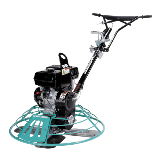
J36 AND B46 SERIES
CENTRIFUGAL CLUTCH
(INCLUDES M30H55)
(HONDA/ROBIN-SUBARU GASOLINE ENGINES)
Revision #0 (10/27/16)
To find the latest revision of this
publication, visit our website at:
www.multiquip.com
THIS MANUAL MUST ACCOMPANY THE EQUIPMENT AT ALL TIMES.
PN: 13401
*AAA Rent-All 225-291-1356*
Advertisement
Table of Contents
Troubleshooting

Related Manuals for MULTIQUIP Whiteman J36 Series


Summary of Contents for MULTIQUIP Whiteman J36 Series
- Page 1 J36 AND B46 SERIES CENTRIFUGAL CLUTCH (INCLUDES M30H55) (HONDA/ROBIN-SUBARU GASOLINE ENGINES) Revision #0 (10/27/16) To find the latest revision of this publication, visit our website at: www.multiquip.com THIS MANUAL MUST ACCOMPANY THE EQUIPMENT AT ALL TIMES. PN: 13401 *AAA Rent-All 225-291-1356*...
-
Page 2: Proposition 65 Warning
*Always follow manufacturer instructions* PROPOSITION 65 WARNING Engine exhaust some its constituents, and some dust created by power sanding, sawing, grinding, drilling and other construction activities contains chemicals known to the State of California to cause cancer, birth defects and other reproductive harm. Some examples of these chemicals are: Lead from lead-based paints. -
Page 3: Silicosis/Respiratory Warnings
*Always follow manufacturer instructions* SILICOSIS/RESPIRATORY WARNINGS WARNING WARNING SILICOSIS WARNING RESPIRATORY HAZARDS Grinding/cutting/drilling of masonry, concrete, metal and Grinding/cutting/drilling of masonry, concrete, metal and other materials with silica in their composition may give other materials can generate dust, mists and fumes off dust or mists containing crystalline silica. -
Page 4: Table Of Contents
*Always follow manufacturer instructions* TABLE OF CONTENTS J36 AND B46-SERIES/M30 WALK-BEHIND POWER TROWELS Proposition 65 Warning ........... 2 Silicosis/Respiratory Warnings ........ 3 Table Of Contents ............ 4 Training Checklist ............ 5 Daily Pre-Operation Checklist ......... 6 Safety Information ..........7-11 Specifications ........... -
Page 5: Training Checklist
*Always follow manufacturer instructions* TRAINING CHECKLIST Training Checklist Description Date Read operation manual completely. Machine layout, location of components, checking of engine oil level. Fuel system, refueling procedure. Operation of controls (machine not running). Safety controls, safety stop switch operation. Emergency stop procedures. -
Page 6: Daily Pre-Operation Checklist
*Always follow manufacturer instructions* DAILY PRE-OPERATION CHECKLIST Daily Pre-Operation Checklist Engine oil level Gearbox oil level Condition of blades Blade pitch operation Safety stop switch operation PAGE 6 — J36/B46-M30 SERIES WALK-BEHIND TROWELS • OPERATION MANUAL — REV. #0 (10/27/16) *AAA Rent-All 225-291-1356*... -
Page 7: Safety Information
*Always follow manufacturer instructions* SAFETY INFORMATION Do not operate or service the equipment before reading Potential hazard associated with the operation of this equipment will be referenced with hazard symbols which the entire manual. Safety precautions should be followed at all times when operating this equipment. may appear throughout this manual in conjunction with Failure to read and understand the safety safety messages. - Page 8 „ NEVER use accessories or attachments that are not „ Avoid wearing jewelry or loose fi tting clothes that may recommended by Multiquip for this equipment. Damage snag on the controls or moving parts as this can cause to the equipment and/or injury to user may result.
- Page 9 *Always follow manufacturer instructions* SAFETY INFORMATION TROWEL SAFETY „ ALWAYS keep work area clear around the trowel. DANGER Make sure it is free of debris and objects. „ Engine fuel exhaust gases contain poisonous carbon monoxide. This gas is colorless and odorless, and can cause death if inhaled.
- Page 10 *Always follow manufacturer instructions* SAFETY INFORMATION „ Store fuel in appropriate containers, in well-ventilated NOTICE areas and away from sparks and fl ames. „ NEVER run engine without an air fi lter or with a dirty air „ NEVER use fuel as a cleaning agent. fi lter.
- Page 11 *Always follow manufacturer instructions* SAFETY INFORMATION ENVIRONMENTAL SAFETY/DECOMMISSIONING EMISSIONS INFORMATION NOTICE NOTICE Decommissioning is a controlled process used to safely The gasoline engine used in this equipment has been retire a piece of equipment that is no longer serviceable. designed to reduce harmful levels of carbon monoxide If the equipment poses an unacceptable and unrepairable (CO), hydrocarbons (HC) and nitrogen oxides (NOx) safety risk due to wear or damage or is no longer cost...
-
Page 12: Specifications
*Always follow manufacturer instructions* SPECIFICATIONS Table 1. J-Series Trowel Specifications Model J36H55/J36R60/J36S60 J36H90/J36R90 J36H90H/J36R90H M30H55 Number of Blades Ring Diameter 36 in. (914 mm) 30 in. (762 mm) Rotor - RPM 60 - 115 60 - 130 90 - 155 60 - 130 Path Width 34.5 in (876 mm) - Page 13 *Always follow manufacturer instructions* SPECIFICATIONS Table 4. Engine Specifications (Continued) HONDA SUBARU Model GX340U1QAP2 EX270D5E5013 Trowel B46H11/B46H11H B46S90 Air-cooled 4 stroke, Single Cylinder, OHV, Air-cooled 4 stroke, Slant Single Cylinder, Type Horizontal PTO Shaft Gasoline Engine OHC, Horizontal PTO Shaft Gasoline Engine 3.2 in.
-
Page 14: Noise And Vibration Emissions
*Always follow manufacturer instructions* NOISE AND VIBRATION EMISSIONS Table 5. J-Series Trowel Noise and Vibration Emissions MODEL J36H55 J36R60 J36S60 J36H90 J36R90 J36H90H J36R90H M30H55 Guaranteed ISO Quick Pitch 90.79 11201:2010 Based Handle Sound Pressure Standard Level at Operator 90.79 Handle Station in dB(A) Quick Pitch... -
Page 15: Dimensions
*Always follow manufacturer instructions* DIMENSIONS TOP VIEW A A A SIDE VIEW Standard Handle Shown Figure 1. Dimensions Table 7. Trowel Dimensions MODEL J36 Series M30H55 B46 Series A–Height (Lifting Bale) – in. (mm) 27 (686) 31.5 (800) 26 (661) Standard B–Height (Handle) –... -
Page 16: General Information
5.4 HP to 11.0 HP. Refer to the engine owner’s manual the assistance of another person to help lift the trowel. for instructions regarding the operation and maintenance of your engine. Please contact your nearest Multiquip Dealer TRAINING for a replacement if the original manual is lost or becomes unusable. - Page 17 *Always follow manufacturer instructions* NOTES J36/B46-M30 SERIES WALK-BEHIND TROWELS • OPERATION MANUAL — REV. #0 (10/27/16) — PAGE 17 *AAA Rent-All 225-291-1356*...
-
Page 18: Trowel Components
*Always follow manufacturer instructions* TROWEL COMPONENTS QUICK PITCH ™ HANDLE (OPTION) Figure 2. Trowel Components PAGE 18 — J36/B46-M30 SERIES WALK-BEHIND TROWELS • OPERATION MANUAL — REV. #0 (10/27/16) *AAA Rent-All 225-291-1356*... - Page 19 *Always follow manufacturer instructions* TROWEL COMPONENTS 10. Handlebar Adjuster — Change the angle/height of the Figure 2 shows the location of the basic components for the trowel. Listed below is a brief explanation of each handle bars by loosening star wheel. Adjust handlebar component.
-
Page 20: Engine Components
*Always follow manufacturer instructions* ENGINE COMPONENTS CLOSE OPEN HONDA GX ROBIN-SUBARU EX Figure 3. Honda/Robin Subaru Basic Engine Components INITIAL SERVICING 6. Fuel Valve Lever – OPEN to let fuel flow, CLOSE to The engine (Figure 3) must be checked for proper stop the flow of fuel. -
Page 21: Assembly And Installation
This section provides general instructions on ordering P/N 2576 from your Multiquip dealer. how to install those components. For more detailed handle... - Page 22 *Always follow manufacturer instructions* ASSEMBLY AND INSTALLATION Pitch Cable Installation 1. For Standard Handle models extend the pitch cable to maximum length by turning the blade pitch star wheel (Figure 9) fully counterclockwise for no pitch (blades flat). DECREASE INCREASE BLADE PITCH BLADE PITCH (CCW)
- Page 23 *Always follow manufacturer instructions* ASSEMBLY AND INSTALLATION 4. Thread brass set nut #2 (Figure 11) towards the cable 7. Use a wrench and finish tightening the brass set #1 as far as possible. nut up against the yoke boss. 5. Insert the cable end through the yoke eyelet Pre-Load Adjustment (Quick Pitch™...
-
Page 24: Inspection
*Always follow manufacturer instructions* INSPECTION 4. If the oil level is low (Figure 15), fill to the edge of the CAUTION oil filler hole with the recommended oil type as listed ALWAYS wear approved eye and hearing in Table 8. Reference Table 3 for maximum engine oil protection before operating the trowel. - Page 25 *Always follow manufacturer instructions* INSPECTION Gearbox Oil Also, examine the belt and determine if it is oil soaked or "glazed " (hard shiny appearance on the sides of the belt). 1. Determine if the gearbox oil is low by removing the oil Either of these two conditions can cause the belt to run hot, plug located on the side of the gearbox.
- Page 26 *Always follow manufacturer instructions* INSPECTION/OPERATION Blade Check Check for worn or damaged trowel blades (Figure 20). Check to see if one blade is worn out while the others look new. If this is the case there could be a blade pitch problem. Refer to the maintenance section of this manual for blade pitch adjustment procedure.
-
Page 27: Operation
*Always follow manufacturer instructions* OPERATION Starting the Engine NOTICE 1. Place the engine fuel valve lever (Figure 23) in the The trowel is heavy and awkward to move around. Use OPEN position. proper heavy lifting procedures and DO NOT lift the trowel by the guard rings. - Page 28 *Always follow manufacturer instructions* OPERATION 4. Place the centrifugal safety "STOP" switch (Figure 26) in the "ON" position. HONDA GX ROBIN-SUBARU CHOKE CHOKE LEVER LEVER CLOSE OPEN OPEN OPEN CENTRIFUGAL SAFETY “STOP” SWITCH Figure 28. Choke Lever (Open) Figure 26. Centrifugal Safety"Stop" Switch (ON) 7.
- Page 29 *Always follow manufacturer instructions* OPERATION Concrete Finishing Techniques The following steps are intended as a basic guide to machine operation, and are not to be considered a complete guide to concrete finishing. We suggest that all operators (experienced and novice) read “Slabs on Grade” published by the American Concrete Institute, Detroit, Michigan.
- Page 30 *Always follow manufacturer instructions* OPERATION Maneuvering the Trowel 3. Continue to practice maneuvering the trowel. Try to practice as if you were finishing a slab of concrete. 1. Get into the operator’s position behind the handle. With Practice edging and covering a large area. a secure foothold and a firm grasp on the handle, slowly Remember a good finishing technique is to work increase the engine speed until the desired blade speed...
- Page 31 *Always follow manufacturer instructions* OPERATION Stopping The Engine 3. Place the safety stop switch (Figure 38) in the OFF position. 1. Move the throttle lever to the (Figure 36) IDLE position and run the engine for three minutes at low speed. IDLE THROTTLE LEVER...
-
Page 32: Options
If you need replacement blades, consult the parts list in this manual for part numbers and order them from your Multiquip parts dealer or importer. Combo Blades This trowel is equipped with combination float/finish (Figure Figure 42. Clip-On Float Blade 40) blades as original equipment. - Page 33 *Always follow manufacturer instructions* OPTIONS Trowel Arm Adjustment Tool (Optional) If blades show uneven wear patterns or some tend to wear out faster than others, the trowel arms may need to be adjusted. A special tool is available (Figure 44) that will adjust all of the trowel arms consistently.
-
Page 34: Maintenance
*Always follow manufacturer instructions* MAINTENANCE Table 9. Engine Maintenance Schedule EVERY 6 EVERY BEFORE FIRST EVERY 2 DESCRIPTION MONTHS YEAR OPERATION EACH MONTH OR YEARS OR OR 100 OR 300 20 HRS. 500 HRS. HRS. HRS. Check Engine Oil Change Engine Oil Filter Replace Every 200 Hrs. - Page 35 *Always follow manufacturer instructions* MAINTENANCE GENERAL CLEANLINESS General maintenance practices are crucial to the performance and longevity of your trowel. This equipment Clean the trowel daily. Remove all dust and slurry buildup. requires routine cleaning, blade and trowel arm inspection, If the trowel is steam-cleaned, ensure that lubrication is lubrication and V-belt inspection for wear and damage.
- Page 36 *Always follow manufacturer instructions* MAINTENANCE ENGINE OIL 1. Drain the engine oil when the oil is warm as shown in Figure 48. 2. Remove the oil drain bolt and sealing washer and allow the oil to drain into a suitable container. 3.
- Page 37 *Always follow manufacturer instructions* MAINTENANCE V-BELT SPARK ARRESTER CLEANING Visually examine the V-belt (Figure 50) and determine if it Clean the spark arrester every 6 months or 100 hours. is full of tiny cracks, frayed, has pieces of rubber missing, 1.
- Page 38 *Always follow manufacturer instructions* MAINTENANCE BLADE PITCH ADJUSTMENT PROCEDURE 2. Pitch the blades as flat as possible. The pitch adjustment bolts (Figure 55) should all barely make The maintenance adjustment of blade pitch is an adjustment contact (0.10 inch max. clearance) with the lower wear that is made by a bolt (Figure 54) on the arm of the trowel plate on the spider.
- Page 39 *Always follow manufacturer instructions* MAINTENANCE SPIDER REMOVAL CHANGING BLADES Remove the spider assembly from the gearbox shaft as It is recommended that ALL the blades on the trowel follows: are changed at the same time. If only one or some of the blades are changed, the machine will not finish concrete 1.
- Page 40 *Always follow manufacturer instructions* MAINTENANCE TROWEL ARM REMOVAL 1. Use a thick steel plate, granite slab or any surface which is true and flat, to check all six sides of each 1. Each trowel arm is held in place at the spider plate trowel arm for flatness (Figure 61).
- Page 41 *Always follow manufacturer instructions* MAINTENANCE REASSEMBLY 1. Unscrew the locking bolts on the adjustment fixture and place the trowel arm (lever attached) into the fixture 1. Clean and examine the upper/lower wear plates and channel as shown in Figure 62. thrust collar.
- Page 42 *Always follow manufacturer instructions* MAINTENANCE LONG-TERM STORAGE assembly. 12. Reinstall square head cone point into spider plate and For storage of the trowel for over 30 days, the following is tighten in place. Tighten jam nut. Use care in making required: sure point of set screw engages groove in gear box „...
-
Page 43: Troubleshooting (Engine)
*Always follow manufacturer instructions* TROUBLESHOOTING (ENGINE) Troubleshooting (Engine) Symptom Possible Problem Solution Spark plug bridging? Check gap, insulation or replace spark plug. Carbon deposit on spark plug? Clean or replace spark plug. Short circuit due to defi cient spark plug Check spark plug insulation, replace if worn. - Page 44 *Always follow manufacturer instructions* TROUBLESHOOTING (ENGINE) Troubleshooting (Engine) - continued Symptom Possible Problem Solution Air cleaner dirty? Clean or replace air cleaner. Improper level in carburetor? Check fl oat adjustment, rebuild carburetor. Weak in power, compression is proper and does not misfi re. Defective spark plug? Clean or replace spark plug.
-
Page 45: Troubleshooting (Trowel)
*Always follow manufacturer instructions* TROUBLESHOOTING (TROWEL) Troubleshooting (Walk-Behind Trowel) Symptom Possible Problem Solution Engine ON/OFF Switch in "OFF" position Make sure that the Engine ON/OFF Switch is ON or malfunctioning? or replace switch if necessary. Centrifugal ON/OFF Switch in "OFF" Place centrifugal stop switch in "ON"... - Page 46 *Always follow manufacturer instructions* TROUBLESHOOTING (TROWEL) Troubleshooting (Walk-Behind Trowel) - continued Symptom Possible Problem Solution The main output shaft of the gearbox assembly should be checked for straightness. Main shaft? The main shaft must run straight and cannot be more than 0.003"" (0.08 mm) out of round at the spider attachment point.
-
Page 47: Wiring Diagram
*Always follow manufacturer instructions* WIRING DIAGRAM CENTRIFUGAL STOP SWITCH SPARK OIL LEVEL ENGINE OIL ALERT IGNITION UNIT PLUG SWITCH STOP UNIT COIL SWITCH TRANSISTORIZED OIL LEVEL IGNITION UNIT INDICATOR CHASSIS GND. J36/B46-M30 SERIES WALK-BEHIND TROWELS • OPERATION MANUAL — REV. #0 (10/27/16) — PAGE 47 *AAA Rent-All 225-291-1356*... - Page 48 © COPYRIGHT 2016, MULTIQUIP INC. Multiquip Inc , the MQ logo are registered trademarks of Multiquip Inc. and may not be used, reproduced, or altered without written permission. All other trademarks are the property of their respective owners and used with permission.