
Related Manuals for Samsung MIM-B18


Summary of Contents for Samsung MIM-B18
-
Page 1: Air Conditioner
Air Conditioner imagine Thank you for purchasing this Samsung product. DB98-32140A(3) user manual the possibilities Data Management Server2 MIM-D00A BACnet Gateway MIM-B17 LonWorks Gateway MIM-B18... -
Page 2: Safety Precautions
Safety Precautions • Before using the DMS2, read carefully these instructions. • After reading the instructions, keep this user's manual in a handy and safe place. If a user is changed, you must hand over the manuals. • Never attempt to install the air conditioning system or to move the DMS2 by yourself. WARNING CAUTION D o not attempt to install or repair this DMS2 by yourself. -
Page 3: Table Of Contents
Contents ... 4 ENERAL ESCRIPTION ... 6 IEWING THE ARTS ... 8 EFORE ... 10 UNCTION DMS2 ... 14 TARTING ... 18 ONTROL AND ONITORING ... 45 ANAGEMENT ... 50 CHEDULE EHP P ... -
Page 4: General Description
General Description Introduction of DMS2 (Data Management Server2) The DMS2 is an Internet based device for central management of Samsung system air-conditioners. It supports LAN & WAN and operates 24 hours without a separate PC. Advantages of DMS2 System The DMS2 provides the following advantages: ... - Page 5 Terms DMS2: The abbreviation of Data Management Server2. Upper Controller: It means S-NET Series, a local controller of the DVM system. S-NET 3, S-NET mini and RMS are linked to a DMS2. Centralized Controller: A device that controls 16 groups of the DVM air conditioner. A central control device of a DVM system which is located between a DMS2 and an outdoor unit interface module.
-
Page 6: Viewing The Parts
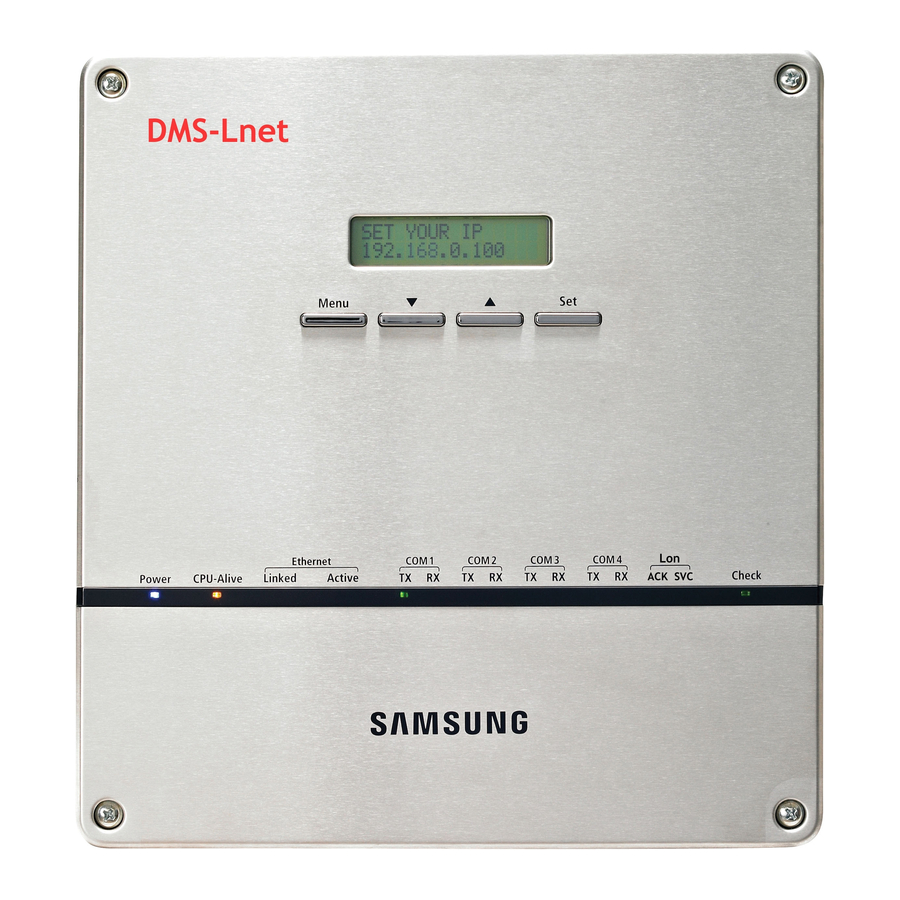
Viewing the Parts Front View Name LCD Display Display current time/ Check menu Menu button Access to main menu Select the function you want and set detailed functions in ▼/▲ button main menu Check the function you want from main menu Set button and select it Unfasten 2 screws on the bottom and separate the bottom... -
Page 7: Reset Button
Bottom View Separate bottom cover by unfastening 2 screws on the bottom. DI Terminal2 Connect Digital Input - Channel 6~Channel10 DI Terminal1 Connect Digital Input - Channel 1~Channel 5 Power Terminal Connect DMS2 adapter Reset Button Reset DMS2 Serial Terminal Service agent checks error status SD Card Socket... -
Page 8: Before Use
Before Use System Configuration S-NET mini ⓐ Centralized controller Interface module Connecting centralized controller and DMS2 (ⓐ type ) You can control up to 16 centralized controllers and 256 indoor units using DMS2. Connecting interface module and DMS2 (ⓑ type) - You can control up to 80 interface modules and 256 indoor units using DMS2. - Page 9 When connecting centralized controller and interface module to the DMS2 of same communication channel, only one of them will communicate according to the communication channel mode setting of [System Settings][Tracking]. Therefore, do not connect the centralized controller and interface module to the same communication channel.
-
Page 10: Main Function
Main Function Interface with Upper Level Controller The DMS2 receives/manages setting and control data from the upper level controller and sends the received data to the lower level system. The upper level controllers of the DMS2 are the S-NET series and the connectible S-NET series are S-NET 3, S-NET mini and RMS. - Page 11 Set and Run Schedule The schedule function of the DMS2 can be set through the Web or using the upper level controller. 1day/Everyday/Every week schedules can be set. Each schedule can be used selectively by using the run schedule/stop schedule order. ...
-
Page 12: System Architecture
Main Function (Continued) Save Integrated Power Distribution Data The DMS2 calculates and distributes the power consumed by each indoor unit by receiving the total power usage from the watt-hour meter interface modules (SIM/PIM) and taking into account the operation status of the indoor units. The DMS2 saves at most 1 year of data. -
Page 13: Time Segmentation
Time Segmentation Time segmentation is used to divide 24 hours into different sections and to distribute power according to each section. This function is used when the power consumption fee is different according to different time slots or when a building is charged differently depending on the consumption time. -
Page 14: Starting Dms2
Starting DMS2 Starting DMS2 Current time setting Set the current time of DMS2 system. “2009/01/01 01:01:01” is factory setting. Set the current time as DMS2 system time. You can set DMS2 time in [System Settings] [System environment setting] (Refer to page 104~105) If DMS2 time does not set as the current time, DMS2 may cause malfunction when using Schedule or control logic management. - Page 15 Access to DMS2 & Login Address bar Run internet explorer on your computer. Enter IP address (http://192.168.0.100) on the address bar, and then press [ENTER]. If it is the first access to DMS2, “Install Microsoft Silverlight” message will be displayed. - The message will not appear if Microsoft Silverlight have already installed.
- Page 16 Starting DMS2 (Continued) Enter ID and password when DMS2 main web page appears. Then click [LOGIN]. The default DMS2 user ID is 'admin' and password is '1234'. Click [Connect] to log in as a regular user. Depending on authorization settings which set by the administrator, access to some functions may be restricted.
- Page 17 Logged-in User with No Authorization When the screen above appears, ask for manager. D epending on control authorization setting, there can be a user who does not have control authorization. A bove screen will appear when the logged-in user does not have control authorization.
-
Page 18: Control And Monitoring
Control and Monitoring DMS2 Controllable Devices Type Indoor unit display icon ERV display icon AHU display icon DI(Digital Input) display icon DO(Digital Output) display icon Display Remote controller (Controlling range) If the user select several devices, the remote controller of last selected device will be displayed on the screen. - Page 19 Monitoring Indoor Unit Operation Status Click [Control and Monitoring] when DMS2 web page menu screen appears. [Control and Monitoring] screen will appear when you log-in to DMS2 web page. Check the current status of all devices. You can check current status of all installed indoor units, ERV, AHU, DI and DO.
- Page 20 Control and Monitoring (Continued) Controlling Indoor Unit Status display window Click [Control and Monitoring] when DMS2 web page menu screen appears. [Control and Monitoring] screen will appear when you log-in to DMS2 web page. Select indoor unit to control. ...
- Page 21 Select the operation mode. You can select Auto, Cool, Dry, Fan or Heat operation mode. Click [∧][∨] to set the desired temperature. Each time you click the buttons, the temperature will be adjusted by 1℃(1°F). If Auto/Cool/Dry mode is in operation, you can adjust the desired temperature in the range of 18℃(65°F)~ 30℃(86°F).
- Page 22 Control and Monitoring (Continued) Select the air flow. You can select Vertical, Horizontal, All and None air flow. Set remote controller settings. You can select ON, OFF and Level1. When selecting [OFF], indoor unit control by wired/ wireless remote controller and indoor unit panel is not possible.
- Page 23 Indoor Unit Operation Mode Limit Status display window Click [Control and Monitoring] when DMS2 web page menu screen appears. [Control and Monitoring] screen will appear when you log-in to DMS2 web page. Select indoor unit to control. Check the indoor unit status through status display window.
- Page 24 Control and Monitoring (Continued) Set operation mode limit. You can select 'Cool only(Fan, Cool)’, ‘Heat only(Fan, Heat)’ and ‘No limits’. - Cool only (Fan, Cool): If cooling only indoor unit operates in heat mode, indoor - Heat only (Fan, Heat): If heating only indoor unit operates in cool mode, reset the - No limits: You can use cooling only and heating only with no limits.
- Page 25 Setting Lower/Upper Temperature Limit of Indoor Unit Status display window Click [Control and Monitoring] when DMS2 web page menu screen appears. [Control and Monitoring] screen will appear when you log-in to DMS2 web page. Select indoor unit to control. ...
- Page 26 Control and Monitoring (Continued) Set lower temperature limit by pressing [∧] and [∨]. You can set lower temperature limit by checking 'Apply'. When indoor unit is operating in cool mode, DMS2 controls indoor unit as lower temperature limit if the desired temperature is lower than lower temperature limit.
- Page 27 Monitoring AHU Operation Status Click [Control and Monitoring] when DMS2 web page menu screen appears. [Control and Monitoring] screen will appear when you log-in to DMS2 web page. Check current status of AHU. Note To control AHU, refer to ‘Controlling indoor unit’ steps. - AHU’s fan speed is fixed as high.
- Page 28 Control and Monitoring (Continued) Monitoring ERV Operation Status Click [Control and Monitoring] when DMS2 web page menu screen appears. [Control and Monitoring] screen will appear when you log-in to DMS2 web page. Check current status of ERV.
- Page 29 Controlling ERV Click [Control and Monitoring] when DMS2 web page menu screen appears. [Control and Monitoring] screen will appear when you log-in to DMS2 web page. Select an ERV to control. Check ERV status through status display window. Turn ERV on by pressing [ON].
- Page 30 Control and Monitoring (Continued) Select the operation mode. You can select Auto, HeatEx, By pass and Sleep. Select the fan speed. You can select Low, High and Turbo. Fan speed is set to Low in sleep mode. Set remote controller settings.
- Page 31 Monitoring DMS DI/DO Operation Status Click [Control and Monitoring] when DMS2 web page menu screen appears. [Control and Monitoring] screen will appear when you log-in to DMS2 web page. Check the current status of DI and DO device. Click [Detail] to see the control window of selected device. Monitor the device through the detail control window.
- Page 32 Control and Monitoring (Continued) Controlling DMS DO Click [Control and Monitoring] when DMS2 web page menu screen appears. [Control and Monitoring] screen will appear when you log-in to DMS2 web page. Select DO device to control when control and monitoring screen appears.
- Page 33 Checking the Installation Information You can check the installation status of currently connected device. Click [Control and Monitoring] when DMS2 web page menu screen appears. [Control and Monitoring] screen will appear when you log-in to DMS2 web page. Check installation status of currently connected device in the installation information tab.
- Page 34 Control and Monitoring (Continued) View the Control History & Power Consumption You can select a device and view control history and power consumption information. Click [Control and Monitoring] when DMS2 web page menu screen appears. [Control and Monitoring] screen will appear when you log-in to DMS2 web page.
- Page 35 When data reception is completed from DMS2, check control history and power consumption of selected device. Note In ‘Control history’ , you can check power control and remote controller usage status. Operation mode, desired temperature, air flow and fan speed control shows you the controlled time and type of control only.
- Page 36 Control and Monitoring (Continued) Cycle Monitoring You can select an indoor unit and check cycle information. Click [Control and Monitoring] [Cycle Monitoring] when DMS2 web page menu screen appears. Click [Select]. DMS2 installation information will be displayed. Select a device to check cycle information. ...
- Page 37 Indoor Unit Usage Restriction_Operation Limit You can set the operation of indoor unit as cooling only and heating only. Click [Control and Monitoring] [Indoor unit usage restriction] when DMS2 web page menu screen appears. Press [Edit] button. Set the limit mode. ...
- Page 38 Control and Monitoring (Continued) Set the control mode. If you set the control mode, indoor unit operating in limited operation mode will be automatically set to operate in pre-set control mode. You can set the different control mode to each of the indoor units. - Cooling only indoor unit: You can select fan or cool mode.
- Page 39 Indoor Unit Usage Restriction_Temperature Limit in Cool/Heat mode You can set temperature lower/upper temperature limit in cool/heat mode. Click [Control and Monitoring] [Indoor unit usage restriction] when DMS2 web page menu screen appears. Press [Edit] button.
- Page 40 Control and Monitoring (Continued) Set the lower/upper temperature limit. You can set lower/upper temperature limit by selecting 'Enable'/'Disable'. If desired temperature is lower than lower limit temperature when the indoor unit is operating in cool mode, DMS2 controls indoor unit to lower temperature limit.
- Page 41 Checking the Trouble History Click [Control and Monitoring] [Trouble history] when DMS2 web page menu screen appears. Check all the trouble history. You can check address, device type, occurrence time, resolution time, code number and status. You can check detailed information on trouble history by selecting the item in the list.
- Page 42 Control and Monitoring (Continued) Checking the Trouble History by Date DMS2 saves maximum 1024 trouble histories. If the number of history exceeds 1024, DMS2 will delete the oldest history first. Click [Control and Monitoring] [Trouble history] when DMS2 web page menu screen appears. Enter the time period you want to check.
- Page 43 Deleting the Trouble History Click [Control and Monitoring] [Trouble history] when DMS2 web page menu screen appears. Select trouble history you want to delete. Click [Delete]. Click [OK] from the confirm window. Selected trouble history will be deleted.
- Page 44 Control and Monitoring (Continued) Checking the Operation Status You can check operation status of indoor unit which is controlled by DMS2. Click [Control and Monitoring] when DMS2 web page menu screen appears. Check the operation history. You can check the device type, occurrence time, control unit, control type, and controlled device address of indoor unit which is controlled by DMS2 and subordinate controller.
-
Page 45: Zone Management
Zone Management Zone Setting & Edit – Individual/Group Initialization Click [Zone management] [Zone Setting & Edit] when DMS2 web page menu screen appears. Same screen will be displayed even if you click [Zone management] only. Initialize the indoor unit organization as individual by clicking [Individual]. ... - Page 46 Zone Management (Continued) Zone Setting & Edit – Setting the User Authorization Click [Zone management] [Zone Setting & Edit] when DMS2 web page menu screen appears. Same screen will be displayed even if you press [Zone management] only. Set user authorization for each zone.
- Page 47 Zone Setting & Edit – Zone Edit Click [Zone management] [Zone Setting & Edit] when DMS2 web page menu screen appears. Same screen will be displayed even if you press [Zone management] only. Click [Zone Edit]. Zone edit screen will be displayed.
- Page 48 Zone Management (Continued) Click [▼] to set viewing option of zone edit list. You can select from viewing by 'Name’, ‘Address’ and ‘Address & Name'. Edit item you want. Create in the Create a new zone on top of the selected zone. above Create in the Create a new zone under the selected zone.
- Page 49 Click [Remove disappeared] to remove all disappeared devices which were found after tracking. Change zone properties. You can select “General”, “AHU”, and “Group”. Mode Property name Virtual group which is managed by installation address, not by RMC General address The user can create and delete zone.
-
Page 50: Schedule
Schedule Creating New schedule You can set, edit, delete and use the schedules for air conditioner control. Click [Schedule] [Schedule setting] when DMS2 web page menu screen appears. Click [Register] in the schedule setting screen. Note It is not available to provide the schedule information to BMS system. - Page 51 Enter the schedule name when the schedule setting screen appears. Select schedule period you want by clicking calendar. If you select 'No limit' when setting end date, it means there is no period and it displays Dec 31st, 9999. To set the end date, remove the check of ‘No limit’...
- Page 52 Schedule (Continued) To cancel the added exception date, select the exception date it( ) and click [Delete]. Maximum 365 exception dates can be saved.
- Page 53 Click [Add indoor] to select an indoor unit to apply. All the connected indoor units list will be displayed. To cancel the indoor unit selection, select ( unit again and click [Delete]. ) the indoor...
- Page 54 Schedule (Continued) Click [∨] to select repeat schedule you want and set an event. You can select 'Weekly', 'Everyday' and '1day'. However, the starting and end date should be same when you select '1day'. Enter 4 digits for ON/OFF time setting. Ex) 8:00 ...
- Page 55 Click [Save]. Set schedule information is saved in DMS2. Click [Cancel] to cancel schedule setting. Note If you select dry mode among basic modes, auto fan speed is only available. When the operation mode is ‘Auto’ , fan speed is always set to ‘Auto’...
- Page 56 Schedule (Continued) Editing Schedule Click [Schedule] [Schedule setting] when DMS2 web page menu screen appears. Select the schedule to edit. For the currently operating schedule, you can only check it. Click [Edit]. Edit schedule when the schedule edit screen appears. ...
- Page 57 Deleting Schedule Click [Schedule] [Schedule setting] when DMS2 web page menu screen appears. Select the schedule to delete. Click [Delete]. Click [OK] in confirm window and selected schedule will be deleted. Deleting schedule is possible only when the schedule is in stop status.
- Page 58 Schedule (Continued) Applying schedule Click [Schedule] [Schedule setting] when DMS2 web page menu screen appears. Select the schedule you want to use. Use schedule functions by clicking [Run] and [Stop]. To apply the selected schedule, click [Run]. To stop the selected schedule, click [Stop]. Note ...
- Page 59 Checking Schedule Control History Click [Schedule] [Checking schedule control history] when DMS2 web page menu screen appears. Select a date to check and then click [Search]. Only executed schedules can be searched. You can check detailed setting by clicking the schedule name.
-
Page 60: Ehp Power Consumption Inspection
EHP Power Consumption Inspection Checking Inspection Result (with SIM/PIM) You can check the operation history and power consumption saved in DMS for each indoor unit. Click [EHP Power Consumption Inspection] [Check inspection result] when DMS2 web page menu screen appears. Set date and search condition (power consumption/proportion/individual indoor unit by date) when inspection result screen appears. - Page 61 Checking Inspection Result (without SIM/PIM) Click [EHP Power Consumption Inspection] [Check inspection result] when DMS2 web page menu screen appears. Channel setting by indoor unit must be done in advance. Set date when inspection result screen appears. Select year/month/day in order. ...
- Page 62 EHP Power Consumption Inspection (Continued) Check the power consumption result of the selected period. Due to rounding the actual values, actual input value and result value may different to each other. If you want to save the consumption result for selected period as MS Excel file, click [Save as Excel].
- Page 63 Setting the Inspection Section Click [EHP Power Consumption Inspection] inspection section] when DMS2 web page menu screen appears. Click [Edit] when inspection result screen appears. 1 section is set as default. Select a section and enter time by section. ...
- Page 64 EHP Power Consumption Inspection (Continued) Setting and Checking Watt-Hour Meter Click [EHP Power Consumption Inspection] [Setting and checking watt-hour meter] when DMS2 web page menu screen appears. Setting watt-hour meter is possible only when SIM/PIM is installed. Click [Edit] when the setting and checking watt-hour meter screen appears. ...
- Page 65 Checking Kilowatthour History Click [EHP Power Consumption Inspection] [Setting and Checking watt-hour meter] when DMS2 web page menu screen appears. Click [Kilowatthour history] when the setting and checking watt-hour meter screen appears. Select SIM/PIM address and date you want when the kilowatthour history screen appears.
- Page 66 EHP Power Consumption Inspection (Continued) Setting and Checking Virtual Channel Click [EHP Power Consumption Inspection] [Setting and checking virtual channel] when DMS2 web page menu screen appears. Maximum 128 virtual channels can be set. Virtual channel is written in (24 ~ 31).(1 ~ 16) format address.
- Page 67 Channel Setting by Indoor Unit Click [EHP Power Consumption Inspection] [Channel setting by indoor unit] when DMS2 web page menu screen appears. Click [Edit] when the setting channel by indoor unit screen appears.
- Page 68 EHP Power Consumption Inspection (Continued) Check the address and channel information of SIM/PIM which is connected to watt- hour meter. If 0~7 SIM/PIM units execute tracking, it will be displayed as 16~23 in DMS2. Below table shows the channel information of the terminal which SIM and watt- hour meter is connected.
- Page 69 Check the virtual channel information of indoor/outdoor unit. To execute power distribution without SIM/PIM, you should set virtual channel. When bringing indoor unit’s power from outdoor unit, set the ‘Outdoor unit virtual channel’ information only. ( ‘Outdoor unit virtual channel’ is referring to watt-hour meter which is connected to outdoor unit.) ...
- Page 70 EHP Power Consumption Inspection (Continued) Checking Indoor Unit Operation Time Click [EHP Power Consumption Inspection] indoor unit operation time] when DMS2 web page menu screen appears. Select search condition (All indoor units by period/ Individual indoor unit by date) when Checking indoor unit operating time screen appears.
-
Page 71: Control Logic Management
Control Logic Management Setting Control Logic ■ Control logic is used in the following situations. Ex) The current temperature of the lab is higher than 29℃ and you want cooling operation, The current temperature of the office is lower than 10℃ and you want heating operation ■... - Page 72 Control Logic Management (Continued) Enter control logic name in the name field when the new control logic setting screen appears. You can use maximum 16 letters. Set period, day and time in control logic screen. Select year/month/day in order. ...
- Page 73 Select a factor in the input list. Factor means the target to be controlled or standard item of logic decision. Select the type of factor. Single: It means 1 device. Ex) Desired temperature of indoor unit Arithmetic: It means 2 devices are connected by arithmetic operator. Ex) Desired temperature of indoor unit 1 –...
- Page 74 Control Logic Management (Continued) Select a device. List of device which you can select will be displayed. Select the device to use as factor. Control and monitoring items will be displayed depending on selected device. Control and monitoring items are as follows. Type Power Current temp.
- Page 75 Select detailed item of factor. Detailed item may be different depending on the type of selected device. Click [Apply]. If you do not click [Apply], changed setting will not be saved. Select comparison operator. Types of comparison operators: = , =< , => , < , >, ≠ ...
- Page 76 Control Logic Management (Continued) Select standard value. Select detailed item value of selected factor or factor. The item varies depending on the left factor when selecting detailed item value from standard value. Ex1) Factor : Current temperature of indoor unit 1, Value of standard value: Enter 29 Ex2) Factor : Remote controller usage of indoor unit 1, Value of standard value: Select one among On, Off and Level1...
- Page 77 Select compound factor setting usage. You can use compound factor setting when you give conditions to 2 and 3 input items. You can select 1 compound factor from 'AND' and 'OR'. Select 'AND' if all the input items each should be ‘True'. ...
- Page 78 Control Logic Management (Continued) Select type of factor. Single factor can be set for the left factor of output. - Single factor: It means 1 device. Ex) Desired temperature of indoor unit Select a device. List of device which can be selected will be displayed. Select the device to use as factor.
- Page 79 Select detailed item of factor. Detailed item may be different depending on the type of selected device. Click [Apply]. If you do not click [Apply], changed setting will not be saved. Select command value. The value may vary depending on the detailed item of selected factor. ...
- Page 80 Control Logic Management (Continued) To add output, click [Add]. If you want to delete output which you don't use anymore, select it and then click [Delete]. Click [Save]. Set control logic will be saved in DMS2. If you do not click [Save], changed setting will not be saved. Note ...
- Page 81 Editing/Deleting/Copying Control Logic Click [Control logic management] when DMS2 web page menu screen appears. Select control logic when control logic screen appears. Click [Edit]/[Delete]/[Copy]. To edit control logic, refer to 'Setting control logic' steps. (Refer to page 71~80) Click [Delete] to delete the selected control logic. ...
- Page 82 Control Logic Management (Continued) Enable/Disable Control Logic Click [Control logic management] when DMS2 web page menu screen appears. Select control logic when control logic screen appears. Click [Apply]/[Not apply]. The selected control logic will be applied by clicking [Apply]. ...
- Page 83 Checking Control History Click [Control logic management] [Checking control history] when DMS2 web page menu screen appears. Select the date you want when the control logic screen appears. Select Year/Month/Day in order. Based on DMS2 time, you can check of maximum 180 days of previous control history.
-
Page 84: System Settings
System Settings Adding a User You can add, edit and delete the user of DMS2. Click [System Settings] appears. Click [Add user] when user management screen appears. User information input window will be appeared when pressing [Add user]. Enter ID, password, name and description for new user and then select authority. ... - Page 85 Editing a User Click [System Settings] [User management] when DMS2 web page menu screen appears. Click the user name to edit when user management screen appears. User information window will be displayed. Edit user information when the user information window appears. ...
- Page 86 System Settings (Continued) Deleting a User Click [System Settings] [User management] when DMS2 web page menu screen appears. Click the user name to delete when user management screen appears. User information window will be displayed. Click [Delete] when the user delete window appears. ...
- Page 87 Editing User Authorization Click [System Settings] [User authorization management] when DMS2 web page menu screen appears. Select/Deselect accessible menu by authorization when the user authorization management screen appears. Click [Save] after setting is completed. Click [OK] when “Successfully done.” message appears. ...
- Page 88 System Settings (Continued) Initializing a User Authorization Click [System Settings] [User authorization management] when DMS2 web page menu screen appears. Click [Initialize] when user management screen appears. Click [OK] when “Successfully done.” message appears. User authorization information saved in DMS2 will be initialized by clicking [OK].
- Page 89 DMS2 Data Backup – PC Backup You can back up DMS2 data to PC or SD card. Click [System Settings] [Data backup & restoration] when DMS2 web page menu screen appears. Click [PC backup] when DMS2 data backup & restoration screen appears.
- Page 90 System Settings (Continued) Click [OK] when “Backup file is ready. Click "OK" to download.” message appears. Click [Save] when “File download” window appears.
- Page 91 When “Save as” window appears, select saving location and file name and then click [Save]. Backup file will be saved as the name you made in the location you select by clicking [Save]. Basic backup file name is “DMS2dataYYYYMMDD.dms”. (YYYY: year, MM : month, DD : day) ...
- Page 92 System Settings (Continued) DMS2 Data Backup – SD card backup You can back up DMS2 data to PC or SD card. Click [System Settings] [Data backup & restoration] when DMS2 web page menu screen appears. Click [SD card backup] when DMS2 data backup & restoration screen appears.
- Page 93 Click [OK] when “DMS2 data backup completed. The created file name is as follows: DMS2dataYYYYMMDD.dms" message appears. The file name of backup file is “DMS2dataYYYYMMDD.dms” and it does not exceed maximum 15 letters. (YYYY: year, MM: month, DD: day) ...
- Page 94 System Settings (Continued) DMS2 Data Restoration - PC Restore Click [System Settings] [Data backup & restoration] when DMS2 web page menu screen appears. Enter the password of Admin account when DMS2 data backup and restoration screen appears. Data restoration function deals with the important data of the system.
- Page 95 I want to restore DMS2 data. Click [PC restore]. Click [Browse]. Select DMS2 data file to restore and then click [Open(O)] when “File selection” window appears. Check if the file route and file name are correctly entered in the text box, and then click [Upload]. You can restore DMS2 data which is backed up in PC or SD card.
- Page 96 System Settings (Continued) Click [OK] when “Restore the DMS by using the file. Do you want to continue?” message appears. “Reading data from DMS2. Please wait.” message window will appear. Depending on the size of the data, backup time may vary. It will usually take few seconds.
- Page 97 DMS2 Data Restoration - SD Card Restoration Click [System Settings] [Data backup & restoration] when DMS2 web page menu screen appears. Enter the password of Admin account when DMS2 data backup and restoration screen appears. Data restoration function deals with the important data of the system.
- Page 98 System Settings (Continued) Click [SD card restore]. Select the check box of file to restore. Click [OK].
- Page 99 Click [OK] when “Restore DMS data by using the file. Do you want to continue?” message appears. “Reading data from DMS2. Please wait.” message window appears. Depending on the size of the data, backup time may vary. It will usually takes few seconds. Click [OK] when “Restoration is complete.
- Page 100 System Settings (Continued) Event History Management “Search(Check)” You can search(check) all kinds of set information of event log in DMS2. Click [System Settings] [Event history management] when DMS2 web page menu screen appears. Select the period of event history you want to search. Click [Search].
- Page 101 DMS2 Network Information Setting – “Manual Setting” You can set and check information about DMS2 installation operation. Click [System Settings] [System environment setting] when DMS2 web page menu screen appears. Click [Edit] from DMS2 network information window. When text boxes of IP address, subnet mask address, default gateway and DNS server are enabled, enter values for each item.
- Page 102 System Settings (Continued) DMS2 Network Information Setting – using “DHCP” Click [System Settings] [System environment setting] when DMS2 web page menu screen appears. Click [Edit] from DMS2 network information window. Check 'DHCP'. The text boxes of IP address, subnet mask address, default gateway and DNS server will be disabled.
- Page 103 Note F actory setting is as follows. 1. IP address: 192.168.0.100 2. Subnet mask address: 255.255.255.0 3. Default gateway : 192.168.0.1 4. DNS server: 0.0.0.0 D MS2 sets service engineer IP(192.168.0.254) internally. Therefore, it should be available all the time regardless of current IP setting. ...
- Page 104 System Settings (Continued) System Time Setting Click [System Settings] [System environment setting] when DMS2 web page menu screen appears. Click [Edit] from system time setting. Enter system time(year/month/day/hour/minute/second). You can enter only numbers. Year: You can enter from1980 to 2035. ...
- Page 105 Click [OK] when “This information will be modified. Do you want to proceed?” message window appears. “Reading data from DMS2. Please wait.” message appears and saving is completed. Then, system environment setting screen appears again with all items are disabled. Note ...
-
Page 106: Selecting The Language
System Settings (Continued) Selecting the Language Click [System Settings] [System environment setting] when DMS2 web page menu screen appears. Click [Edit] from language selection. Select a language you want then click [Save]. Click [OK] when “This operation needs DMS to be restarted. Do you want to apply the setting?”... - Page 107 DMS2 Name Setting Click [System Settings] [System environment setting] when DMS2 web page menu screen appears. Click [Edit] from DMS2 name setting. Enter name of DMS2 when DMS2 name field enabled. You can use maximum 30 letters including English alphabets and special symbols.
- Page 108 You can check new DMS2 name on the title bar of web browser. Note N ame of the DMS2 is set to blank as factory default. ‘Samsung electronics DMS2’ is displayed on the title bar of web browser.
- Page 109 Error Mail Forwarding Setting Click [System Settings] [System environment setting] when DMS2 web page menu screen appears. Click [Edit] from error mail forwarding setting. Set all the items as the value you want when all items fields are enabled. ...
- Page 110 System Settings (Continued) Click [OK] when “This information will be modified. Do you want to proceed?” message appears. “Reading data from DMS2. Please wait.” message appears and saving is completed. Then, system environment setting screen appears again with all items are disabled. Note ...
- Page 111 Contact Control Pattern Selection Click [System Settings] [System environment setting] when DMS2 web page menu screen appears. Click [Edit] from contact point pattern selection window. Select the pattern you want to check. Pattern 1[No external input]: No operation will be made when inputting contact control signal.
- Page 112 System Settings (Continued) Click [OK] when “This information will be modified. Do you want to proceed?” message appears. “Reading data from DMS2. Please wait.” message appears and saving is completed. Afterwards, system environment setting screen appears again with all items are disabled. ...
- Page 113 RMS Service Usage Setting ■ RMS settings should be set by expert's instruction. To get RMS service, contact to Samsung electronics service center, ■ RMS settings requires to restart the system in following situations. At this time, system restart will be displayed in the information phrase and restart will be done automatically.
- Page 114 System Settings (Continued) If ‘Use’ is selected, “You must restart DMS for the task: Do you want to proceed applying the setting?” message will appear. To restart DMS2, click [OK]. Then RMS service will be started. If ‘Unuse’ is selected, “This information will be modified. Do you want to proceed?”...
- Page 115 Setting ID for RMS Connection Click [System Settings] [RMS settings] when DMS2 web page menu screen appears. Click [Edit] from RMS service usage settings window. Enter DMS2 ID in connection ID field. DMS2 ID is unique recognizable ID which is created when you add DMS2 in RMS server.
- Page 116 System Settings (Continued) If the ‘Connection ID’ is modified with RMS service usage as ‘Use’ status, “You must restart DMS for the task: Do you want to proceed applying the setting?” message will appear. Click [OK] to restart DMS2. If the ‘Connection ID’ is modified with RMS service usage as ‘Unuse’...
- Page 117 Setting RMS Server Address Click [System Settings] [RMS settings] when DMS2 web page menu screen appears. Click [Edit] from RMS server address setting window. Enter RMS server address in connection address field. Current RMS server address is http://www.dvmcare.com. Click [Save] after entering connection address.
- Page 118 System Settings (Continued) If the ‘Connection address’ is modified with RMS service usage as ‘Use’ status, “You must restart DMS for the task: Do you want to proceed applying the setting?” message will appear. Click [OK] to restart DMS2. If the ‘Connection address’ is modified with RMS service usage as ‘Unuse’...
-
Page 119: Main Menu
System Setting Initialization 192.168.0.100 06:12:13(AM) Press [Menu], [▲], [▼] or [Set] on LCD if IP and current time are displayed on LCD screen. Main menu screen appears. Initialization is not possible in the screen which time information is displayed. - Page 120 System Settings (Continued) Tracking What is tracking? Tracking is an operation that finds devices which are connected to DMS2. Through tracking operation, devices which are connected to DMS2 can recognize if they are connecting to DMS2. To supervise and control system air conditioner using DMS2, tracking should be done first. ...
- Page 121 Communication Mode Setting by Channel Click [System Settings] [Tracking] when DMS2 web page menu screen appears. Click [Edit] from communication mode by channel setting. [Edit] will change to [Cancel]. Selection buttons are enabled. However, the channels which have searched device maintains its selection button disabled.
- Page 122 System Settings (Continued) DVM Tracking Click [System Settings] [Tracking] when DMS2 web page menu screen appears. Click [DVM Tracking].
- Page 123 Enter administrator's password and then click [OK]. Tracking information window pops up. Check and click [OK] to continue. Execute tracking depending on the communication mode set by communication mode setting by channel. (1) For the channel which is set to interface module communication mode, DMS2 executes tracking of interface module and SIM/PIM.
- Page 124 System Settings (Continued) Tracking completed message will appear. Select Zone initialization mode you want and click [OK]. Not initialize: No zone information initialization will be made. Initialize individually: Initialize zone information as individual mode. Initialize by group: Initialize zone information as group mode.
- Page 125 Disconnect All Devices Function Initialize searched device status in DMS2. Using this function, monitoring and controlling of all the connected devices to DMS2 will be stopped. When is it needed? - Connect searched device to the other channel and execute tracking. If the other device is searched in the channel you want to use, use 'Disconnect all devices' function.
- Page 126 System Settings (Continued) Enter administrator's password and then click [OK]. Disconnect all devices information window pops up. Check it and click [OK] to continue. “Reading data from DMS2. Please wait.” message appears. After completing disconnect all devices operation, page will be refreshed.
- Page 127 Renaming the Device Click [System Settings] [Tracking] when DMS2 web page menu screen appears. Click [Edit] on the bottom of tracking device list. [Edit] will change to [Cancel].
- Page 128 System Settings (Continued) Enter name in the name field. You cannot use special symbols as device name. Click [Save] after setting is completed. “Reading data from DMS. Please wait.” message appears and saving is completed. Then, tracking page with disabled items will be displayed again.
- Page 129 DMS DI•DO Port Setting Select [System Settings] and then click [Tracking]. Click [Setting] which is next to DMS DI•DO of device list. Click [Edit] which is on the bottom of DMS DI•DO setting page. [Edit] will change to [Cancel].
- Page 130 System Settings (Continued) Edit each item when DMS DI•DO selection and input fields are enabled. Device type : DI or DO Short name : Input short name of the device. Full name : Input full name of the device. ...
-
Page 131: Pim Setting
PIM Setting Click [System Settings] [Tracking] when DMS2 web page menu screen appears. Click [Setting] which is next to PIM of device list. Enter administrator’s password and then click [OK]. Click [Edit] which is on the bottom of PIM setting page. ... - Page 132 System Settings (Continued) Select a field and edit each item when input fields are enabled. Note Each field range Watt-hour meter: 0~99999.9(kWh) Pulse width: 20~400(ms) Pulse: 1~10000(Wh/Pulse) Click the check boxes to select the channel applying for the setting.
-
Page 133: Check Before Using Panel
Check Before using Panel Using LCD and LCD Button LCD is mounted on DMS2 for installation and convenience of the user. You can search menu and change setting using [▲] and [▼] buttons. If you press and hold [▲] or [▼] button in some menu such as IP setting, the value changes faster. -
Page 134: Setting Network Information
Setting Network Information Network Information Setting(IP Config) 192.168.0.100 06:12:13(AM) 1. Check main menus by pressing [Menu], [▲], [▼] or [Set] button. MAIN MENU 1.IP Config 2. Select 1.IP Config by pressing [▲] and [▼] buttons, and press [Set] button. Network setting screen will be displayed. IP ADDRESS 192.168.0.100 3. - Page 135 Auto Address Setting (DHCP CONFIG) 192.168.0.100 06:12:13(AM) 1. Check main menus by pressing [Menu], [▲], [▼] or [Set] button. MAIN MENU 1.IP Config 2. Select 1.IP Config by pressing [▲] and [▼] buttons, and press [Set] button. Network setting screen will be displayed. DHCP CONFIG Current disabled 3.
-
Page 136: Checking Indoor/Outdoor Unit Information
Checking Indoor/Outdoor Unit Information Checking Indoor/Outdoor Unit Information 192.168.0.100 06:12:13(AM) 1. Check main menus by pressing [Menu], [▲], [▼] or [Set] button. MAIN MENU 2.In/Outdoor 2. Select 2.In/Outdoor by pressing [▲] and [▼] buttons. IN/OUTDOOR INFO Indoor:64 3. Press [Set] button. ... -
Page 137: Checking Dms2 Version
Checking DMS2 Version Checking DMS2 Version 192.168.0.100 06:12:13(AM) 1. Check main menus by pressing [Menu], [▲], [▼] or [Set] button. MAIN MENU 3.DMS Version 2. Select 3. DMS2 Version by pressing [▲] and [▼] buttons. DMS version 3. Press [Set] button. ... - Page 138 Checking DMS2 version (Continued) DMS2 Time Setting – Checking and Setting Date 192.168.0.100 06:12:13(AM) 1. Check main menus by pressing [Menu], [▲], [▼] or [Set] button. MAIN MENU 4.DMS time 2. Select 4. DMS2 Time by pressing [▲] and [▼] buttons. ...
- Page 139 DMS2 Time Setting – Checking and Setting Time 192.168.0.100 06:12:13(AM) 1. Check main menus by pressing [Menu], [▲], [▼] or [Set] button. MAIN MENU 4.DMS time 2. Select 4. DMS2 Time by pressing [▲] and [▼] buttons. Current set time of DMS2 will be displayed. CURRENT TIME 16:46:37(PM) 3.
-
Page 140: Data Backup Setting
Data Backup Setting Data Backup 192.168.0.100 06:12:13(AM) 1. Check main menus by pressing [Menu], [▲], [▼] or [Set] button. MAIN MENU 5.Data Backup 2. Select 5.Data Backup by pressing [▲] and [▼] buttons. DMS BACKUP MENU will appear. DMS BACKUP MENU data backup 3. - Page 141 Data Restore 192.168.0.100 06:12:13(AM) 1. Check main menus by pressing [Menu], [▲], [▼] or [Set] button. MAIN MENU 5.Data Backup 2. Select 5.Data Backup by pressing [▲] and [▼] buttons, and then press [Set] button. DMS BACKUP MENU will appear. DMS BACKUP MENU data restore 3.
-
Page 142: Checking Error Information
Checking Error Information Checking Error Information 192.168.0.100 06:12:13(AM) 1. Check main menus by pressing [Menu], [▲], [▼] or [Set] button. MAIN MENU 7.Error Status 2. Select 7. Error Status by pressing [▲] and [▼] buttons, and then press [Set] button. ... -
Page 143: Reset Password
Reset Password Reset Password 192.168.0.100 06:12:13(AM) 1. Check main menus by pressing [Menu], [▲], [▼] or [Set] button. MAIN MENU 8.Password Reset 2. Select 8.Password Reset by pressing [▲] and [▼] buttons, and then press [Set] button. RESET PASSWORD WAITING... 3. -
Page 144: Button Lock
Button Lock Button Lock 192.168.0.100 06:12:13(AM) 1. Check main menus by pressing [Menu], [▲], [▼] or [Set] button. MAIN MENU 9.Button Lock 2. Select 9.Button Lock by pressing [▲] and [▼] buttons. Are you sure? YES:Set, NO:Menu 3. Press [Set] button. ... -
Page 145: 10.Safety Halt
Safety Halt Safety Halt 192.168.0.100 06:12:13(AM) 1. Check main menus by pressing [Menu], [▲], [▼] or [Set] button. MAIN MENU 10.Safety Halt 2. Select 10.Safety Halt by pressing [▲] and [▼] buttons. Are you sure? YES:Set, NO:Menu 3. Press [Set] button. ... -
Page 146: Troubleshooting
Troubleshooting Problem DMS2 is not working. Is there an electricity failure? Isn’t there a communication error in the other interface module besides centralized controller? Are the adapter and power cable connected? Access to web page is Is Microsoft Silverlight not available. installed? Is Microsoft Silverlight installed properly? - Page 147 Problem I forgot DMS2 IP. Press [Menu] button from the main menu and "1. IP Config" will appear. Then press [Set] button. Indoor unit turned on Isn't the schedule control or off automatically. of peak power control in operation? Is DMS2 system time different from current time? DI(Digital Input) Is the external circuit...
-
Page 148: Specifications
Specifications Items Description Exterior Size 240 X 255 X 64.8 mm ( Width X Length X Height ) Weight 1.48 Kg Source DC ADAPTOR Power INPUT Voltage 100-240V 50/60Hz 1.0A OUTPUT Voltage 12V 3A RS-485 5 Channels Ethernet 10/100Mbps 1 Port SD CARD Inter- Option (Purchase SD card separately) -
Page 149: License
1. Some softwares which distributed under GPL and LGPL are mounted on this product. You can get the source code of GPL and LGPL software by requesting it to oss.request@samsung.com. 1) GPL software - RTL-lwIP, dhcpd, PeerSec Networks MatrixSSL Evaluation base-passwd, bash, bzip2,... - Page 150 Memo...
-
Page 152: Gnu General Public License
GNU GENERAL PUBLIC LICENSE Version 2, June 1991 Copyright (C) 1989, 1991 Free Software Foundation, Inc. 51 Franklin Street, Fifth Floor, Boston, MA 02110-1301, USA Everyone is permitted to copy and distribute verbatim copies of this license document, but changing it is not allowed. Preamble The licenses for most software are designed to take away your freedom to share and... - Page 153 each copy an appropriate copyright notice and disclaimer of warranty; keep intact all the notices that refer to this License and to the absence of any warranty; and give any other recipients of the Program a copy of this License along with the Program. You may charge a fee for the physical act of transferring a copy, and you may at your option offer warranty protection in exchange...
- Page 154 the scripts used to control compilation and installation of the executable. However, as a special exception, the source code distributed need not include anything that is normally distributed (in either source or binary form) with the major components (compiler, kernel, and so on) of the operating system on which the executable runs, unless that component itself accompanies the executable.
- Page 155 Public License from time to time. Such new versions will be similar in spirit to the present version, but may differ in detail to address new problems or concerns. Each version is given a distinguishing version number. If the Program specifies a version number of this License which applies to it and “any later version”, you have the option of following the terms and conditions...
- Page 156 by electronic and paper mail. If the program is interactive, make it output a short notice like this when it starts in an interactive mode: Gnomovision version 69, Copyright (C) year name of author Gnomovision comes with ABSOLUTELY NO WARRANTY; for details type `show w’.
- Page 157 method: (1) we copyright the library, and (2) we offer you this license, which gives you legal permission to copy, distribute and/or modify the library. To protect each distributor, we want to make it very clear that there is no warranty for the free library.
- Page 158 law: that is to say, a work containing the Library or a portion of it, either verbatim or with modifications and/or translated straightforwardly into another language. (Hereinafter, translation is included without limitation in the term “modification”.) “Source code” f o r a w o r k means t he preferred form of the work for making modifications to it.
- Page 159 To do this, you must alter all the notices that refer to this License, so that they refer to the ordinary GNU General Public License, version 2, instead of to this License. (If a newer version than version 2 of the ordinary GNU General Public License has appeared, then you can specify that version instead if you wish.) Do not make any other change in...
- Page 160 can modify the Library and then relink to produce a modified executable containing the modified Library. (It is understood that the user who changes the contents of definitions files in the Library will not necessarily be able to recompile the application to use the modified definitions.) b) Use a suitable shared library mechanism for linking with the Library.
- Page 161 11. If, as a consequence of a court judgment or allegation of patent infringement or for any other reason (not limited to patent issues), conditions are imposed on you (whether by court order, agreement or otherwise) that contradict the conditions of this License, they do not excuse you from the conditions of this License.
-
Page 162: Apache License
AS PERMITTED ABOVE, BE LIABLE TO YOU FOR DAMAGES, INCLUDING ANY GENERAL, SPECIAL, INCIDENTAL OR CONSEQUENTIAL DAMAGES ARISING OUT OF THE USE OR INABILITY TO USE THE LIBRARY (INCLUDING BUT NOT LIMITED T O L O S S O F D ATA O R D ATA B E I N G RENDERED INACCURATE OR LOSSES SUSTAINED BY YOU OR THIRD PARTIES O R A FA I L U R E O F T H E L I B R A RY T O... - Page 163 but not limited to software source code, documentation source, and configuration files. “Object” form shall mean any form resulting from mechanical transformation or translation of a Source form, including but not limited t o c o m p i l e d o b j e c t c o d e , g e n e r a t e d documentation, and conversions to other media types.
- Page 164 Works that You distribute must include a readable copy of the attribution notices contained within such NOTICE file, excluding those notices that do not pertain to any part of the Derivative Works, in at least one of the following places: within a NOTICE text file distributed as part of the Derivative Works;...
- Page 165 for the file format. We also recommend that a file or class name and description of purpose be included on the same “printed page” as the copyright notice for easier identification within third-party archives. Copyright [yyyy] [name of copyright owner] Licensed under the Apache License, Version 2.0 (the “License”);...
- Page 166 Enhydra Public License 1.1 Enhydra PUBLIC LICENSE Version 1.1 1. Definitions This license is a union of the following two parts that should be found as text files in the same place (directory), in the order of preeminence: 1. This file itself, named EPL.html 2.
- Page 167 IN NO EVENT SHALL THE AUTHOR BE LIABLE FOR ANY DIRECT, INDIRECT, INCIDENTAL, SPECIAL, EXEMPLARY, OR CONSEQUENTIAL DAMAGES (INCLUDING, BUT NOT LIMITED TO, PROCUREMENT OF SUBSTITUTE GOODS OR SERVICES; LOSS OF USE, DATA, OR PROFITS; OR BUSINESS INTERRUPTION) HOWEVER CAUSED AND ON ANY THEORY OF LIABILITY, WHETHER IN CONTRACT, STRICT LIABILITY, OR TORT (INCLUDING NEGLIGENCE OR OTHERWISE)
- Page 168 archiving software is widely available for no charge. 1.12. “You” means an individual or a legal entity exercising rights under, and complying with all of the terms of, this License or a future version of this License issued under Section 6.1. For legal entities, “You”...
- Page 169 available, or at least six (6) months after a subsequent version of that particular Modification has been made available to such recipients. You shall notify the Initial Developer of the Modification and the location of the Source Code via the contact means provided for in the Developer Specific license.
- Page 170 compliance with the terms of this License and that the license for the Executable version does not attempt to limit or alter the recipient’s rights in the Source Code version from the rights set forth in this License. If You distribute the Executable version under a different license You must make it absolutely clear that any terms which differ from this License are offered...
- Page 171 In case of conflicting dispositions in the parts of this license, the terms of the lower- numbered part will always be superseded by the terms of the higher numbered part. 7. DISCLAIMER OF WARRANTY. COVERED CODE IS PROVIDED UNDER THIS LICENSE ON AN “AS IS” BASIS, WITHOUT WARRANTY OF ANY KIND, E I T H E R E X P R E S S E D O R I M P L I E D , I N C L U D I N G , W I T H O U T L I M I TAT I O N ,...
- Page 172 UNDER NO LEGAL THEORY, WHETHER T O R T ( I N C L U D I N G N E G L I G E N C E ) , CONTRACT, OR OTHERWISE, SHALL THE INITIAL DEVELOPER, ANY OTHER CONTRIBUTOR, OR ANY DISTRIBUTOR OF COVERED CODE, OR ANY SUPPLIER OF ANY OF SUCH PARTIES, BE LIABLE...
- Page 173 of this license, including the license conditions and limitations in section 3, each contributor grants you a non- exclusive, worldwide, royalty-free license under its licensed patents to make, have made, use, sell, offer for sale, import, and/ or otherwise dispose of its contribution in the software or derivative works of the contribution in the software.
- Page 174 Redistribution and use of this software and associated documentation (“Software”), with or without modification, are permitted provided that the following conditions are met: 1. Redistributions of source code must retain copyright statements and notices. Redistributions must also contain a copy of this document.
- Page 175 development kit, operating system, other library, or a development tool without written permission from the copyright holder. 5. The distribution includes copyright notice as follows: “The source code, object code, and documentation in the com.oreilly.servlet package is copyright and owned by Jason Hunter.”...
- Page 176 L I C E N S E E U N D E R S T A N D S T H A T S O F T W A R E I S P R O V I D E D “ A S I S ” FOR WHICH NO WARRANTIES AS TO C A PA B I L I T I E S O R A C C U R A C Y A R E M A D E .
- Page 177 S L E E P Y C A T S O F T W A R E ` ` A S I S ’ ’ A N D A N Y E X P R E S S O R I M P L I E D WARRANTIES, INCLUDING, BUT NOT LIMITED TO, THE IMPLIED WARRANTIES OF MERCHANTABILITY, FITNESS FOR...
- Page 178 ON ANY THEORY OF LIABILITY, WHETHER IN CONTRACT, STRICT LIABILITY, OR TORT (INCLUDING NEGLIGENCE OR OTHERWISE) ARISING IN ANY WAY OUT OF THE USE OF THIS SOFTWARE, EVEN IF ADVISED OF THE POSSIBILITY OF SUCH DAMAGE. BSD 2.0 [Reviewed and Approved] Copyright (c) <YEAR>, <OWNER>...
- Page 179 IS PROVIDED “AS IS,” AND COPYRIGHT HOLDERS MAKE NO REPRESENTATIONS OR WARRANTIES, EXPRESS OR IMPLIED, I N C L U D I N G B U T N O T L I M I T E D T O , WARRANTIES OF MERCHANTABILITY OR FITNESS FOR ANY PARTICULAR PURPOSE OR THAT THE USE OF THE SOFTWARE...
- Page 180 the Original Work or Derivative Works in any way such that the Original Work or Derivative Works may be accessed or used by anyone other than You, whether the Original Work or Derivative Works are distributed to those persons, made available as an application intended for use over a computer network, or used to provide services or otherwise deliver content to anyone other than You.
- Page 181 conflict-of-law provisions. The application of the United Nations Convention on Contracts for the Inter national Sale of Goods is expressly excluded. Any use of the Original Work outside the scope of this License or after its termination shall be subject to the requirements and penalties of the U.S.
- Page 182 OR PROFITS, WHETHER IN AN ACTION OF CONTRACT, NEGLIGENCE OR OTHER TORTIOUS ACTION, ARISING OUT OF OR IN CONNECTION WITH THE USE OR PERFORMANCE OF THIS SOFTWARE. OpenSSL Combined License LICENSE ISSUES The OpenSSL toolkit stays under a dual license, i.e. both the conditions of the OpenSSL License and the original SSLeay license apply to the toolkit.
- Page 183 distribution, be it the RC4, RSA, lhash, DES, etc., code; not just the SSL code. The SSL documentation included with this distribution is covered by the same copyright terms except that the holder is Tim Hudson (tjh@cryptsoft.com). Copyright remains Eric Young’s, and as such any Copyright notices in the code are not to be removed.
- Page 184 and its contributors. 4. Neither the name of the University nor the names of its contributors may be used to endorse or promote products derived from this software without specific prior written permission. THIS SOFTWARE IS PROVIDED BY THE REGENTS AND CONTRIBUTORS ``AS IS’’...
- Page 185 D I S C L A I M E D . I N N O E V E N T S H A L L JULIE HAUGH OR CONTRIBUTORS BE LIABLE FOR ANY DIRECT, INDIRECT, INCIDENTAL, SPECIAL, EXEMPLARY, OR CONSEQUENTIAL DAMAGES (INCLUDING, BUT NOT LIMITED TO, PROCUREMENT OF SUBSTITUTE GOODS OR SERVICES;...
- Page 186 1. Redistributions qualify as “freeware” or “Open Source Software” under the following terms: a. Redistributions are made at no charge beyond the reasonable cost o f m a t e r i a l s a n d d e l i v e r y. W h e re redistribution of this software is as part of a larger package or combined work, this restriction applies only to...
- Page 187 I N C L U D I N G , B U T N O T L I M I T E D TO, THE IMPLIED WARRANTIES OF MERCHANTABILITY AND FITNESS FOR A PARTICULAR PURPOSE ARE DISCLAIMED. IN NO EVENT SHALL T H E W U - F T P D D E V E L O P M E N T GROUP, THE COPYRIGHT HOLDERS, O R C O N T R I B U T O R S , B E L I A B L E...