Samsung MIM-B17 Installation Manual
Bacnet gateway for air conditioner
Hide thumbs
Also See for MIM-B17:
- User manual (200 pages) ,
- Service manual (67 pages) ,
- User manual (200 pages)

Related Manuals for Samsung MIM-B17


Summary of Contents for Samsung MIM-B17
-
Page 1: Air Conditioner
BACnet Gateway MIM-B17 Air Conditioner installation manual imagine the possibilities Thank you for purchasing this Samsung product. DB98-32390A(3) -
Page 2: Safety Precautions
Safety Precautions This installation manual describes how to install the BACnet Gateway. For installation of other optional accessories, refer to the appropriate installation manual. Read carefully this installation manual before WARNING installation and check if the BACnet Gateway is installed correctly after installation. -
Page 3: Table Of Contents
Contents ............2 afety recautionS ......4 efore nStalling the ateway ..............5 cceSSorieS ............6 iewing the artS ............8 roduct imenSionS ............9 yStem rchitecture ............10 omPatiBle eViceS ........12 nStalling the ateway ... -
Page 4: Before Installing The Bacnet Gateway
Before Installing the BACnet Gateway Checks before installation BACnet Gateway IP A public IP is needed to access the BACnet Gateway over the internet. (One public IP is needed for each BACnet Gateway) A private IP may be used if the BACnet Gateway need not be accessed over the internet. -
Page 5: Accessories
Accessories Make sure you have each item. Supplied items may vary depending on your country or service provider. BACnet Item Adapter Power cable M4 x16 Screw Gateway Quantity Shape Installation User’s manual Cable tie manual The BACnet Gateway must be installed by a trained ... -
Page 6: Led Indicator
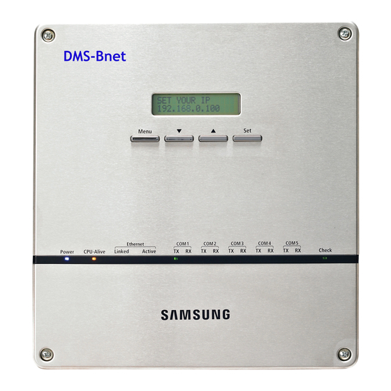
Viewing the Parts Main Parts BACnet Gateway Exterior LCD Display Shows current time and IP address. Various messages will be displayed depending on button input. LCD operation button There are 4 buttons(Menu, (Down), (Up), Set) and you can access to menu and move, check the menu. - Page 7 BACnet Gateway Cable Connection Part RS485 Communication Terminal DI Terminal1 DO Terminal4 DO Terminal3 DI Terminal2 Serial Terminal Cable tie groove Power Terminal SD Card Socket Reset Button Ethernet Terminal Name Description DI Terminal1 Digital Input connection terminal, Channel1~Channel5 DI Terminal2 Digital Input connection terminal, Channel6~Channel10 DO Terminal3 Digital Output connection terminal, Channel1~Channel5...
-
Page 8: Product Dimensions
Viewing the Parts (Continued) Main Parts BACnet Gateway Interior Display Board 20-pin Cable Main Board 40-pin Cable Sub Board Note If you need external circuit configuration, consult with the manufacturer. Product Dimensions (Unit : mm) 64.80... -
Page 9: System Architecture
System Architecture BMS system BMS Engineering Internet SAMSUNG Engineering BACnet Gateway Centralized controller Interface module Interface module Interface module Connecting centralized controller and BACnet Gateway ( type) - You can control up to 16 centralized controllers and 256 indoor units using BACnet Gateway. -
Page 10: Compatible Devices
Pulse type Pulse : 1~10000(Wh/Pulse) Products with ‘* ’ are not Samsung products and must be purchased separately. (Only selected power meters may be used for protocol compatibility issues.) Samsung is not responsible for BMS engineering which creates each device and objects. - Page 11 Maximum Devices Attachable Devices Max. Note Indoor Unit Tracking error occurs if exceeded Centralized Must not exceed 16 units Controller 16 units per 1 channel, total 80 units are connectable when connecting interface module to BACnet Gate- Interface way directly module (256 units are connectable when using centralized controller)
-
Page 12: Installing The Bacnet Gateway
Installing the BACnet Gateway Separate the installation plate on the rear side of BACnet Gateway. Fix the installation plate on the wall using 4 screws. Hang the BACnet Gateway on the groove which is on the top of the installation plate. Installation plate... - Page 13 Fix the installation plate and BACnet Gateway using 2 screws. Depending on the installation environment, fix BACnet Gateway using assistant holes. ( Screws for assistant hole are not provided by our company.) Assistant hole If you install BACnet Gateway inside of the wall or wiring from the rear side is needed, use wiring groove on the bottom of BACnet Gateway.
- Page 14 Installing the BACnet Gateway (Continued) Connecting Centralized Controller Unfasten the 2 screws on the bottom of the BACnet Gateway front cover. Hold the bottom 2 sides of the BACnet Gateway and push downwards to slide open the cover. Connect the adapter to the power terminal. ...
- Page 15 Connecting Interface Module Unfasten the 2 screws on the bottom of the BACnet Gateway front cover. Hold the bottom 2 sides of the BACnet Gateway and push downwards to slide open the cover. Connect the adapter to the power terminal. ...
- Page 16 Installing the BACnet Gateway (Continued) Connecting SIM/PIM Unfasten the 2 screws on the bottom of the BACnet Gateway front cover. Hold the bottom 2 sides of the BACnet Gateway and push downwards to slide open the cover. Connect the adapter to the power terminal. ...
-
Page 17: Setting The Bacnet Gateway
Setting the BACnet Gateway BACnet Gateway Connection and Login Address bar Click internet explorer icon( ) twice on your computer. When internet explorer window appears, enter IP address (http://192.168.0.100) on the address bar then press [ENTER]. If it is the first time to access BACnet Gateway, “ Install Microsoft Silverlight”... - Page 18 Setting the BACnet Gateway (Continued) Click [Run] button and continue installation. After installation, access to BACnet Gateway again. Silverlight operates normally with Windows XP SP2 or later version. It may not operate normally with previous version of Windows.
- Page 19 Enter ID and password when BACnet Gateway main web page appears, Then click [LOGIN]. If you click [Connect], you will be logged in with general user’s authority level. If you use accounts with general authorization level to login, you cannot use the BACnet Gateway settings.
- Page 20 Setting the BACnet Gateway (Continued) If you login successfully, 'Control and Monitoring' screen will appear. Click [System Setting]➔[BACnet configuration] menu to switch to BACnet Gateway. If you use accounts with authorization level lower than management group or accounts with general authorization level, BACnet configuration will not be displayed on the menu.
- Page 21 If you access BACnet Gateway, 'Device Configuration' screen will appear initially. If you click [DMS2 Connect] button, screen will be switched to initial screen.
-
Page 22: Reading Ehp Watt-Hour Meter
Reading EHP Watt-hour Meter Setting and checking watt-hour meter Click [System and Checking Watt-hour meter]. You can change settings on watt-hour meter only when SIM/PIM interface module is connected. Click [Edit] from the 'Setting and checking Watt-hour meter' screen. ... - Page 23 Monthly baseline setting Click [System and Checking Watt-hour meter]. Click [Edit] from the ‘Monthly baseline setting’ screen. You can make changes when list box enables. Set the Monthly baseline setting. You can select from 1~31. If you select the last day of the month, it will automatically set the last day of corresponding month as baseline.
- Page 24 Reading EHP Watt-hour Meter (Continued) Period setting Click [System and Checking Watt-hour meter]. Click [Edit] from the ‘Period setting’ screen. You can select checkbox to set period in daily or monthly unit. If you select daily period setting, text box will be enabled and you can enter the period in daily unit.
- Page 25 Channel setting by indoor unit Click [Channel setting by indoor unit]. Click [Edit] from the ‘Channel setting by indoor unit’ screen. Check the address and the channel information of the SIM/PIM interface module which is connected to the watt-hour meter. ...
- Page 26 Reading EHP Watt-hour Meter (Continued) Check the SIM/PIM interface module channel (Watt-hour meter) information of indoor/outdoor unit. You can set the channel when SIM/PIM interface module is installed in BACnet Gateway. When the indoor unit’s power is supplied from outdoor unit, set the ‘Outdoor unit SIM/PIM channel’...
-
Page 27: System Setting Initialization
System Setting Initialization Press [Menu], [], [] or [Set] from the screen where IP and current time is displayed. Main menu screen appears. Initialization is not possible in the screen where time information is displayed. 192.168.0.100 06:12:13(AM) Press [Menu] [] [] [] [Menu] buttons in order from the main menu screen. -
Page 28: System Settings
System Settings You can set and check information about BACnet Gateway installation and operation. BACnet Gateway network information Click [System Settings]. Click [Edit] from the ‘BACnet network information’ section. When text boxes of IP, Subnet mask, Default gateway, Device Instance No. and DNS server are enabled. - Page 29 When the pop-up window appears, click [OK]. If you click [OK], current internet explorer will be closed. Then you may run the web browser again and access to BACnet Gateway by entering the IP set and saved manually. Note Factory setting is as follows. 1.
- Page 30 System Settings (Continued) System time Click [System Settings]. Click [Edit] from the 'System time' section. Enter system time when text boxes enables. You can only enter numbers. Year: You can enter from 1980 to 2035. Month: You can enter from 1 to 12. ...
-
Page 31: Selecting The Language
Selecting the language Click [System Settings]. Click [Edit] from the 'Select language' section. Select a language you want and click [Save]. When the pop-up window appears, click [OK]. BACnet Gateway will restart and the system will be changed to selected language. - Page 32 System Settings (Continued) Selecting the contact point control pattern Click [System Settings]. Click [Edit] from the 'Select the contact point control pattern' section. Select the pattern you want to check when checkboxes enables. Pattern 1: No operation will be made when inputting contact control signal. ...
- Page 33 When the pop-up window appears, click [OK]. When message with “Reading data from DMS. Please wait” appears saving is completed. Then, 'System Settings' screen appears again with all items disabled. Note Contact point control pattern is set to pattern 1 as factory default. For extension purpose, BACnet Gateway has total of 10 DI/DO ports.
- Page 34 System Settings (Continued) Contact point control pattern Pattern Control ▶ No external input (Factory default setting) Pattern1 When you input contact control signal in port 1, there will be no response. ▶ Level input (Emergency stop) 1. If the contact control signal is changed to ON, emergency stop status and all the indoor units are given ‘Stop’...
- Page 35 DI(Digital Input) Circuitry according to Control Switch Pattern Pattern 2 (May be used for connection with a fire sensor) BACnet Gateway Emergency Stop/Resume Operation No Connection Pattern 3 (External contact signal control) BACnet Gateway Operation/Stop A/C Enable/Disable remote control Pattern 4 (Pulse signal control) ...
- Page 36 System Settings (Continued) BACnet gateway information Click [System Settings]. You can check the basic BACnet gateway information from 'BACnet gateway information' section.
-
Page 37: Tracking
Tracking What is tracking? Tracking is an operation that finds devices connected to BACnet Gateway. Through tracking operation, devices will be recognize if they are connected to BACnet Gateway. To supervise and control system air conditioner using BACnet Gateway, tracking should be done first. - Page 38 Tracking (Continued) Setting communication mode for each channel Click [Device Configuration]. Click [Edit] from the 'Communication mode by channel' screen. [Edit] button will be switched to [Cancel]. All selection buttons will be enabled. However, the channels with searched device maintain its button in disabled status.
- Page 39 When each channel is enabled, check the communication mode you want to set for each channel. You cannot change the communication mode of channel which has currently connected device. If you set interface module as communication mode, tracking/monitoring/ controlling interface module and SIM interface module is possible.
- Page 40 Tracking (Continued) DVM Tracking Click [Device Configuration]. Click [DVM Tracking].
- Page 41 Enter administrator’s password. Click [OK]. When tracking information window pops up, check it and click [OK] to continue. Tracking will be executed regarding on the communication mode set from 'Communication mode by channel' section. Channels with communication mode set to Interface module, tracking will be ...
- Page 42 Tracking (Continued) Message will appear to alert that tracking is completed. Select the zone initializing mode and click [OK]. No initialization: No zone information initialization will be made. Individual initialization: Initialize zone information as individual mode. Group initialization: Initialize zone information as group mode. Page will be refreshed by clicking [OK].
-
Page 43: Device Configuration
Device Configuration Disconnect all devices Function Initialize searched device status in BACnet Gateway. Monitoring and controlling of all the connected devices to BACnet Gateway will be stopped when you use this function. ◆ Connect searched device to the other channel and execute tracking. If the other device is searched in the channel you want to use, use ‘Disconnect all devices’function. - Page 44 Device Configuration (Continued) When the information window pops up, you must check the information and click [OK] to continue. When message with “Reading data from DMS. Please wait” appears and all the devices are disconnected, page will be refreshed. Note ...
- Page 45 Renaming the devices From the list of devices searched by tracking, click [Edit] in the bottom of the list. [Edit] will be changed to [Cancel]. Note If you click [Cancel] button, [Cancel] button will be switched to [Edit] button and the changed name of devices will be restored to original name.
- Page 46 Device Configuration (Continued) Enter the name of the devices when the text box enables. You cannot use special characters within the device name. Click [Save] after setting is completed. If you click [Cancel], text boxes will be disabled and the [Cancel] button will be switched to [Edit].
- Page 47 Checking device information Click one of the Object ID from 'Object ID' column. Detail information of the selected device will be displayed in device information.
- Page 48 Device Configuration (Continued) Analog data of the selected device will be displayed in Analog data. Object ID: Displays ID of the corresponding object. Type: Displays type of the corresponding object. - I: Input (Read Only) - O: Output (Read/Write) - V: Value (Read/Write) ...
- Page 49 Binary data of the selected device will be displayed in Binary data. Object ID: Displays ID of the corresponding object. Type: Displays type of the corresponding object. - I: Input (Read Only) - O: Output (Read/Write) - V: Value (Read/Write) ...
- Page 50 Device Configuration (Continued) Multi-state Data of the selected device will be displayed in Multi-state data. Object ID: Displays ID of the corresponding object. Type: Displays type of the corresponding object. - I: Input (Read Only) - O: Output (Read/Write) - V: Value (Read/Write) ...
-
Page 51: Bacnet Protocol Implementation Conformance Statement
BACnet Protocol Implementation Conformance Statement Date: May 24. 2010 Vendor Name: SAMSUNG Electronics CO., Ltd. Product Name: DMS BACnet Gateway Product Model Number: MIM-B17 Application Software Version: 1.0 Firmware Revision: 1.0 BACnet Protocol Revision: 2.0 Product Description: This product supports BACnet/IP and provide functions to monitor and control status of air conditionerss. - Page 52 BACnet Protocol Implementation Conformance Statement (Continued) SUPPORTED BIBB NAME SUPPORTED REMARKS BIBBS AE-N-A Alarm&Event-Notification-A AE-N-I-B Alarm&Event-Notification Internal-B AE-N-E-B Alarm&Event-Notification External-B AE-ACK-A Alarm&Event-ACK-A AE-ACK-B Alarm&Event-ACK-B AE-ASUM-A Alarm&Event-Summary-A Alarm and Event AE-ASUM-A Alarm&Event-Summary-B Management AE-ESUM-A Alarm&Event-Enrollment Summary-A ...
-
Page 53: S Tandard O Bject T
SUPPORTED BIBB NAME SUPPORTED REMARKS BIBBS DM-R-A Restart-A DM-R-B Restart-B DM-LM-A List Manipulation-A DM-LM-B List Manipulation-B DM-OCD-A Object Creation & Deletion-A Device and DM-OCD-B Object Creation & Deletion-B Network DM-VT-A Virtual Terminal-A Management DM-VT-B Virtual Terminal-B ... - Page 54 If this product is a communication gateway, describe the types of non-BACnet equipment/ networks(s) that the gateway supports: This gateway switches SAMSUNG air conditioner protocol to BACnet protocol to make RS-485 communication possible with the air conditioners connected to gateway.
-
Page 55: T Ypes S Upported
Standard Object Types Supported Object Type Support Description [Indoor temperature], [The power value after the basic date], [The number of hours usage of an indoor unit after the basic date], [Power value within Analog Input period], [The number of hours usage of an indoor unit within period], [Indoor ... -
Page 56: Detail Description Of Object
Detail Description of Object Device Following table shows regulation of device ID and they are created automatically. DNET – Range CPP – Range INDOOR – Range Item [Digit 2] [Digit 3] [Digit 2] Centralized 0~15 000~015 Controller 0~15 100~115 DMS DI/DO 0~15 300~315 400~655... -
Page 57: Bacnet Point List
BACnet Point List Indoor Unit Single indoor unit has following point list. Unit Status value Instance Object Object Object Name Inactive Active Number Type Text-1 Text-2 Text-3 Text-4 Text-5 AC_RoomTemp_xx_ Indoor Temperature °C xxxxxx AC_Temp_Set_xx_ Set temperature °C xxxxxx AC_Cool_LimitTemp_ Setting lower temperature limit °C xx_xxxxxx... - Page 58 BACnet Point List (Continued) AHU Kit Single AHU unit has following point list. Unit Status value Instance Object Object Object Name Inactive Active Number Type Text-1 Text-2 Text-3 Text-4 Text-5 AHU_RoomTemp_xx_ Indoor Temperature °C xxxxxx AHU_Temp_Set_xx_ Set temperature °C xxxxxx Setting lower AHU_Cool_ °C...
- Page 59 Single ERV unit has following point list. Unit Status value Instance Object Object Object Name Inactive Active Number Type Text-1 Text-2 Text-3 Text-4 Text-5 Power On/Off operation BV ERV_Power_xx_xxxxxx ERV_FilterSign_xx_ Filter sign status xxxxxx ERV_FilterSign_Reset_ Filter sign reset xx_xxxxxx ERV_Operation_ Operation mode status Auto HeatEx...
-
Page 60: Centralized Controller
BACnet Point List (Continued) Centralized controller Single Centralized controller has following point list. Instance Object Object Object Name Status value Number Type Centralized controller error Central_Error_ Refer to the list of the code Code integrated error code Interface module Single Interface module has following point list. Instance Object Object... -
Page 61: Other Information
Other Information Object setting when there is communication error If any communication error occurs between the air conditioner devices, the property will be set as below. 1. Reliability property will be set as COMMUNICATION_FAILURE. 2. Fault / Alarm flag of Status_Flags property will be set as TRUE. 3. - Page 62 Memo...