Samsung OfficeServ 7100 Installation Manual
Samsung batter installation manual
Hide thumbs
Also See for OfficeServ 7100:
- Technical manual (709 pages) ,
- Service manual (291 pages) ,
- Installation manual (103 pages)
Table of Contents
Advertisement
Advertisement
Table of Contents

Related Manuals for Samsung OfficeServ 7100


Summary of Contents for Samsung OfficeServ 7100
-
Page 1: Installation Manual
OfficeServ 7100 Installation Manual... - Page 2 This manual is proprietary to SAMSUNG Electronics Co., Ltd. and is protected by copyright. No information contained herein may be copied, translated, transcribed or duplicated for any commercial purposes or disclosed to the third party in any form without the prior written consent of SAMSUNG Electronics Co., Ltd.
-
Page 5: Introduction
INTRODUCTION Purpose OfficeServ 7100 is the most suitable system for offices using circuit lines with 10 to 25 subscribers. This manual describes the condition for OfficeServ 7100 system installation and how to install, inspect and operate the system. Document Content and Organization This document consists of eight chapters, and abbreviations as follows: CHAPTER 1. -
Page 6: Conventions
OfficeServ 7100 system. CHAPTER 8. Starting the System This chapter describes items to check before starting the OfficeServ 7100 system, the procedure for starting the system, and the procedure for testing whether the system is normally operating after startup. -
Page 7: Reference
This document introduces OfficeServ 7100 and describes the system information, such as hard configuration, specification, and functions, necessary for this system. OfficeServ 7100 Programming Manual This document describes how to use the MMC program to change the OfficeServ 7100 system setting by using a phone. Revision History... - Page 8 Ошибка! Стиль не определен. This page is intentionally left blank. © SAMSUNG Electronics Co., Ltd.
-
Page 9: Safety Concerns
Symbols Caution Indication of a general caution Restriction Indication for prohibiting an action for a product Instruction Indication for commanding a specifically required action © SAMSUNG Electronics Co., Ltd. OfficeServ 7100 Installation Manual... -
Page 10: Warning
Ошибка! Стиль не определен. Warning Caution for Grounding - Do not connect the grounding wire of the OfficeServ 7100 system to a power conduit of a building - The standards for power and grounding should comply with the country standard and the pertinent work should be conducted according to the country standard. -
Page 11: Caution
Caution Caution for Installation Only a trained service staff can install the OfficeServ 7100 system. The equipment intended only for installation in a RESTRICTED ACCESS LOCATION Caution for the connection of External Batteries Do not connect an external AC power until the battery and the system is completely disconnected. - Page 12 Particular attention should be given to supply connections other than direct connections to the branch circuit (e.g. use of power strips)." Prohibition of Metal Accessories Do not wear metal accessories such as rings and watches to prevent electric damages to the system. VIII © SAMSUNG Electronics Co., Ltd.
- Page 13 The OfficeServ 7100 system only use 230 V. Do not change the input power freely by means of the selector switch. AC Power Connection Inhibited Do not operate other devices with the AC power of the OfficeServ 7100 system or with the DC power of external batteries. Check of Power-off Check if the cabinet power is off when mounting boards on slots.
- Page 14 Ошибка! Стиль не определен. This page is intentionally left blank. © SAMSUNG Electronics Co., Ltd.
-
Page 15: Table Of Contents
Cautions for Installation... 2-4 2.3.2 Tools Required ... 2-4 2.3.3 Installing in a Rack ... 2-4 Installing on a Wall ... 2-4 2.4.1 Tools Required ... 2-4 2.4.2 Installing on a Wall ... 2-4 © SAMSUNG Electronics Co., Ltd. OfficeServ 7100 Installation Manual... - Page 16 CHAPTER 7. Connecting Stations and Additional Equipment Connecting Stations ...7-4 7.1.1 Cautions for Connecting Stations...7-4 7.1.2 Connecting Analog Phones...7-4 7.1.3 Connecting Digital Phones...7-4 7.1.4 Connecting IP Phones ...7-4 7.1.5 Connecting to a Door Phone and a Door Lock...7-4 © SAMSUNG Electronics Co., Ltd.
- Page 17 Station Call Function ... 8-4 8.4.2 Station Camp-On Function... 8-4 8.4.3 C.O. Line Call Function ... 8-4 8.4.4 C.O. Line Camp-On Function ... 8-4 ABBREVIATION 4 ~ I...IV K ~ W...IV © SAMSUNG Electronics Co., Ltd. OfficeServ 7100 Installation Manual XIII...
- Page 18 Figure 2.11 Installation on a Wall (6) ...2-4 Figure 2.12 Installation on a Wall (7)...2-4 Figure 2.13 Grounding ...2-4 Figure 3.1 Front/rear View of OfficeServ 7100 Cabinet...3-4 Figure 3.2 Setting Switches of MP10/11 Board...3-4 Figure 3.3 Mounting a Modem Board on the MP10/11 Board ...3-4 Figure 3.4 Mounting 4SWM/4DLM on the MP10/11 Board ...3-4...
- Page 19 Table 3.6 Interface Boards that can mount option boards ... 3-4 Table 3.7 Interface Board Types and Available Slots... 3-4 Table 6.1 Line condition of OfficeServ 7100 ... 6-4 Table 7.1 Distance Between Stations and the System ... 7-4 Table 7.2 Specification of the SMDR System ... 7-4...
- Page 20 Ошибка! Стиль не определен. This page is intentionally left blank. © SAMSUNG Electronics Co., Ltd.
-
Page 21: Chapter 1. Before Installing
Select a site that satisfies the following conditions for safety, temperature and humidity: 1.1.1 Safety Conditions The OfficeServ 7100 system should not be installed near materials that can cause a fire, such as explosive gas and inflammables. The OfficeServ 7100 system should not be near equipments that generate electromagnetic waves, such as monitors or copying machines. -
Page 22: Grounding Conditions
Cautions for Grounding - Do not connect the grounding wire of the OfficeServ 7100 system to a power conduit of a building. - The standards for power and grounding should comply with the country standard and the pertinent work should be conducted according to the country standard. -
Page 23: Checking The Package
1.4 Checking the Package The list of items included in the OfficeServ 7100 package is as follows: Category Cabinet Basic Cabinet Cable Power Cable Battery Cable Items for Bracket for attaching Cabinet 19” Rack Screws for attaching Cabinet Installation Other Screws... - Page 24 CHAPTER 1. Ошибка! Стиль не определен. This page is intentionally left blank. © SAMSUNG Electronics Co., Ltd.
-
Page 25: Chapter 2. Installing Cabinets
6) Connect input power of AC 230 V.. 2.2 Selecting Installation Method The OfficeServ 7100 cabinet can be installed on the ground, inside a 19-inch rack or on a wall depending on the number of cabinets and environment of the installation area. -
Page 26: Installing In A Rack
The procedure for installing the OfficeServ 7100 cabinet inside a 19-inch rack is as follows: 1) Attach the cabinet bracket to the bottom surface of the OfficeServ 7100 cabinet and fasten the bracket firmly with the two screws. Figure 2.1 Tools for the Installation inside a Rack Figure 2.2 Rack Installation (1) -
Page 27: Figure 2.3 Rack Installation (2)
3) Align the two holes of the cabinet bracket and the holes of the rack brackets, and fasten the cabinet to the rack with the two screws. © SAMSUNG Electronics Co., Ltd. OfficeServ 7100 Installation Manual Figure 2.3 Rack Installation (2) -
Page 28: Installing On A Wall
Four Mount locking screws 2.4.2 Installing on a Wall The way to install the OfficeServ 7100 cabinet by using a wall-type bracket is as follows: 1) There are four holes for the screws on the top/bottom of the bracket(A positions of the figure below). -
Page 29: Figure 2.7 Installation On A Wall (2)
4) Align the screw holes of the wall-type bracket to the position that the plastic anchors are driven. Insert screws to each hole and tighten the screws with a philips screw driver. © SAMSUNG Electronics Co., Ltd. Figure 2.7 Installation on a Wall (2) Figure 2.8 Installation on a Wall (3) -
Page 30: Figure 2.10 Installation On A Wall (5)
5) Two screws exists into the two screw holes among the four screw holes on the bottom side of the OfficeServ 7100 cabinet. Unscrew two screws with a screw driver about 2 mm. 6) Tighten the mount locking screws into the remained two holes among the four screw holes on the bottom of the OfficeServ 7100 cabinet. -
Page 31: Figure 2.12 Installation On A Wall (7)
OfficeServ 7100 Installation Manual 7) Align the screws on the bottom of the OfficeServ 7100 cabinet to the bracket holes, then pull down the cabinet to fix the cabinet completely. 2 mm Figure 2.12 Installation on a Wall (7) © SAMSUNG Electronics Co., Ltd. -
Page 32: Connecting The Grounding Wire
Ring Terminal should be UL Listed Lug Terminal used. As shown in the figure below, ground to the ground lug behind the OfficeServ 7100. Checking external grounding After installing the OfficeServ 7100 system, make sure that the GND in the back side of the system cabinet is connected to the external ground for communication before the operation. -
Page 33: Cabinet Configuration
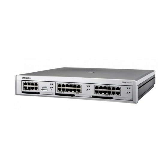
CHAPTER 3. Boards This chapter describes how to mount and replace various boards of the OfficeServ 7100 system. 3.1 Cabinet Configuration The cabinet of the OfficeServ 7100 System has three slots that can install boards. Front Slot 0 Rear Figure 3.1 Front/rear View of OfficeServ 7100 Cabinet ©... -
Page 34: Table 3.1 Mountable Boards On Slots
- OS 7200 Card: 8/16DLI2, 8/16SLI2, 8COMBO, 8TRK, TEPRI, LIM, MGI, - OS7400 Card: TEPRI2, MGI64 Power on/off the OfficeServ 7100 system. Connector for the power cable connection The LED indicates the input of AC power. The LED indicates the normal output of DC power. -
Page 35: Mounting Control Boards
To store the data in the database, operate the system after turning on the S1 switch. SW1~SW4 SW6~SW8 © SAMSUNG Electronics Co., Ltd. Figure 3.2 Setting Switches of MP10/11 Board Table 3.3 Switches of MP10/11 Board Description the pins are set the country code that the system will be used. -
Page 36: Figure 3.3 Mounting A Modem Board On The Mp10/11 Board
Screws are basically locked to the support beside P13. Unscrew and position the screws to the connector direction of 4SWM/4DLM before mounting 4SWM/4DLM. After that, tighten the screws fitting with the grooves of 4SWM/4DLM. Figure 3.4 Mounting 4SWM/4DLM on the MP10/11 Board MODEM 4SWM © SAMSUNG Electronics Co., Ltd. -
Page 37: Mounting Control Boards
3.2.2 Mounting Control Boards Mount a control board to the slot 0 of the OfficeServ 7100 cabinet. For the locations of slot 0 to slot 2, refer to ‘3.1. Cabinet Configuration’. Control Board MP10/11 Mount the MP10/11 board as follows: 1) Check if the MP10/11 board to be mounted is damaged. -
Page 38: Mounting Interface Boards
Card supports DTMF and Dial Pulse dialing Jumper/Switch Setting Setting E1, T1/E1/PRI, 24B+D/24B, User/Network and 17H/13H Setting T1, E1, T1/E1,PRI, 24B+D/24B, User/Network and 1AH Option Board 4DLM or 4SWM, MODEM 4TRM, 2BRM, 4DLM, 4SLM Jumper/Switch Function © SAMSUNG Electronics Co., Ltd. -
Page 39: Figure 3.7 Mounting The Uni Board
Align the module to be mounted to the top connector(16-pin connector). After that, match the bottom connector(100-pin connector). Mount two connectors grasping both connectors. Lock the supporter between the grooves and the top of each option board with screws. © SAMSUNG Electronics Co., Ltd. 4SLM 4TRM Figure 3.7 Mounting the UNI Board... -
Page 40: Figure 3.8 Setting The Switch Of The Tepri Board
Figure 3.8 Setting the Switch of the TEPRI Board SW 1 SW 2 T1/E1 SW 3 24B + D SW 4 User SW 5 Not-used SW 6 Not-used SW 7 Not-used SW 8 Network AFT(Automatic Function Test) Not-used Not-used © SAMSUNG Electronics Co., Ltd. -
Page 41: Figure 3.9 Setting Switches Of The Tepri2 Board
Figure 3.9 Setting Switches of the TEPRI2 Board Setting Jumpers J1, J2, J3 and J4: Connect #1 and #2 for E1 cable, #2 and #3 for T1 cable © SAMSUNG Electronics Co., Ltd. OfficeServ 7100 Installation Manual T1/E1 24B + D... -
Page 42: Figure 3.10 Plim Board
CHAPTER 3. Ошибка! Стиль не определен. 3.3.1.5 PLIM Board The OfficeServ 7100 system does not support the power to the PLM board. Therefore, the PLIM board does not support PoE and only performs the same function as that of the LIM board. -
Page 43: Mounting Interface Boards To Slots
1) Check the exterior of the interface board for any damages. 2) Align each Interface board to the guardrail of the universal slot of the OfficeServ 7100 basic cabinet or expansion cabinet, and slide the Interface board into the slot. -
Page 44: Figure 3.12 Inserting A Control Board To The Connector Of The Main Board
CHAPTER 3. Ошибка! Стиль не определен. 3) Press and lock the lever on the front panel of the interface board to fully insert to the connector of the OfficeServ 7100 main board. Figure 3.12 Inserting a control Board to the Connector of the Main Board ©... -
Page 45: Connecting Power Fail Transfer
Pin 4 and 5 in 8TRK. In power failure, emergency calls can be available since the C.O. line is directly connected to the phone by the internal relay operation. Figure 3.13 Connecting Power Fail Transfer to a 16SLI2/8SLI Board © SAMSUNG Electronics Co., Ltd. OfficeServ 7100 Installation Manual 3-13... -
Page 46: Replacing Boards
CHAPTER 3. Ошибка! Стиль не определен. 3.5 Replacing Boards If the OfficeServ 7100 system fails to operate normally due to an error on the power supply board, control board, or interface board, replace the board to a new one. Removing Cables Replace a board after removing all cables connected to the board. -
Page 47: Figure 3.16 Replacing A New Board
3) Align the new board to the guardrail of the slot, and slide the new board into the slot. After then, lock the lever in the front panel of the board to fully insert into the connector of the OfficeServ 7100 main board. Figure 3.16 Replacing a New Board ©... - Page 48 CHAPTER 3. Ошибка! Стиль не определен. This page is intentionally left blank. © SAMSUNG Electronics Co., Ltd. 3-16...
-
Page 49: Chapter 4. Connecting External Batteries
This chapter describes how to connect external batteries. 4.1 Cautions for Connecting External Batteries External batteries are required to ensure stable operation of the OfficeServ 7100 system in case a power failure occurs. The rated capacity of an external battery is DC 48V per cabinet. -
Page 50: Figure 4.1 Connecting An External Battery
The procedure for using a battery cable to connect an external battery to the OfficeServ 7100 system is as follows: 1) Prepare the battery cable that was provided with the OfficeServ 7100 system. An end of this battery cable consists of a white line and a black line. -
Page 51: Chapter 5. Connecting The Power
Unit(PSU), which charges the external battery. If the input power is interrupted, the system can be operated using the charged power of the external battery. Cautions to be taken when connecting power to the OfficeServ 7100 system are as follows: AC power of the system only supports 230V. -
Page 52: Figure 5.1 Connecting The Power (Use Of A Cabinet)
5.2 Connecting the Power Single cabinet configuration Use the power cable provided with the OfficeServ 7100 system to connect the input power terminal on the back panel of the basic cabinet to a grounded outlet. Figure 5.1 Connecting the Power (use of a cabinet) -
Page 53: Chapter 6. Connecting C.o. Line
CHAPTER 6. This chapter describes how to connect the C.O. line to the OfficeServ 7100 system after installation. 6.1 Line Conditions Cautions for connecting C.O. lines are as follows: Us the cables with AWG #24 or AWG #26 thickness. When wiring cables in high-humidity areas, remove moisture before wiring. -
Page 54: Connecting The C.o. Line
6.2.2 Connecting Common C.O. Line Use a pair of AWG #24(or AWG #26) cable to connect a common C.O. line to the terminal pin of a terminal box connected to the OfficeServ 7100 system equipped with a 4TRM or 2BRM board. -
Page 55: Connecting T1/E1/Pri
TEPRI boards can be connected to a T1/E1 C.O. line through a RJ-45 port. As shown below, connect a T1 type C.O. line or an E1 type PRI C.O. line to the T1/E1/PRI port of the TEPRI/TEPRI2 built in the OfficeServ 7100 system. Pin No. -
Page 57: Connecting Stations
Comply with the manual of the station and with this document when reconnecting stations or changing connections. Connect stations to a pair of #24 AWG or #26 AWG cables. The distances between stations and the OfficeServ 7100 system are as follows: Table 7.1 Distance Between Stations and the System Installation Distance... -
Page 58: Connecting Analog Phones
7.1.2 Connecting Analog Phones Connect an analog phone to the 4SLM of the UNI board, 8SLI/16SLI2, 8COMBO or UNI board mounted on the OfficeServ 7100 system. Connecting to the 4SLM of a UNI Board Connect an analog phone to the ports of a 4SLM of the UNI board by using a pair of AWG #24 or AWG #26 cables. -
Page 59: Figure 7.3 Rj-45 Port Of 8Combo Board (For Analog Phone Connection)
Connect an analog phone to the ports of a 8COMBO board by using a pair of AWG #24 or AWG #26 cables. P1-P8 Ports Pin No. Function Figure 7.3 RJ-45 Port of 8COMBO Board (for Analog Phone Connection) © SAMSUNG Electronics Co., Ltd. P1-P8 Ports (RJ-45) SLI TIP RING OfficeServ 7100 Installation Manual... -
Page 60: Connecting Digital Phones
Connect a digital phone to the ports of a 8DLI board by using a pair AWG #24 or AWG #26 cables. P1-P16 Ports Pin No. Function Figure 7.5 RJ-45 Port of a 8DLI (for a digital phone) P1-P4 Ports (RJ-45) RING Figure 7.4 RJ-45 Port of 4DLM Board P1-P8(P16) Ports (RJ-45) RING © SAMSUNG Electronics Co., Ltd. -
Page 61: Figure 7.6 Rj-45 Port Of 8Combo Board (For Digital Phone)
Maximum number of DS-5012L phones connectable Up to eight DS-5012L phones can be connected to each DLI board(8DLI/16DLI2) of the OfficeServ 7100 system. If more than eight DS-5012L phones are connected to the DLI board, the power for all digital phones connected to the same board is blocked automatically. -
Page 62: Connecting Ip Phones
IP phone is a phone that provides calls through Ethernet LAN. The interface between a digital phone connected to the OfficeServ 7100 system and an IP phone connected to LAN is as follows. In default, the MP10/11 board supports eight MGI channels. Therefore, IP phones are available even if additional MGI16/MGI64 boards are not mounted. -
Page 63: Connecting To A Door Phone And A Door Lock
7.1.5 Connecting to a Door Phone and a Door Lock Connect a door phone and a door lock to the OfficeServ 7100 system by using a Door Phone Interface Module(DPIM). Connect a pair of #24 AWG or #26 AWG cables to the LINE port of DPIM and the ports of 8DLI/16DLI2/8COMBO/4DLM board of the OfficeServ 7100 system. -
Page 64: Connecting Additional Equipment
OfficeServ 7100 system. 7.2.1 Connecting MOH/BGM Equipment The OfficeServ 7100 system offers music when while on hold. The system provides internal tone/music and external music sources per C.O. or extension lines as the music source. The selection of internal/external music sources is performed through MMC 861. -
Page 65: Connecting External/Additional
OfficeServ 7100 system. Connect external/additional page equipment to the MISC port of the MP10/MP11 board mounted on the OfficeServ 7100 system. The power of the external/additional page equipment should be separately connected. -
Page 66: Changing System Setting
PC. Setting Network parameter by using the MMC830 program Set the network parameter of the OfficeServ 7100 system. For the setting value of the network parameter, contact the network administrator. 1) Set the IP address of the OfficeServ 7100 system. -
Page 67: Connecting Smdr
The SMDR computer can be connected via the LAN port of the 4SWM board or the MP10/11 board built in the OfficeServ 7100 system. SMDR system specification is as follows: Category... -
Page 68: Connecting Printers
SMDR computer to the LAN. OfficeServ 7100 7.2.6 Connecting Printers The OfficeServ 7100 system can connect to printers. The system can print various call information or event information created by the system in real time whenever an event occurs. -
Page 69: Pre-Check
CHAPTER 8. This chapter describes items to check before starting the OfficeServ 7100 system, the procedure for starting the system, and the procedure to test the operation of the system. 8.1 Pre-Check This section describes items to check before starting the OfficeServ 7100 system. - Page 70 Halor 1301 and Carbon Dioxide. Make sure that the input power of the OfficeServ 7100 system should be AC 230 V and do not use together with other electric devices, such as motors and compressors.
-
Page 71: Starting The System
1) Check if the boards and cables are properly mounted and connected to the OfficeServ 7100 cabinet. 2) Turn on the power of the OfficeServ 7100 basic cabinet, and turn on the power of the expansion cabinet. 3) Check the LEDs for the MP10/11 boards mounted on the OfficeServ 7100 cabinet. -
Page 72: Numbering Extensions And C.o. Lines
CHAPTER 8. Ошибка! Стиль не определен. 8.3 Numbering Extensions and C.O. Lines Once the OfficeServ 7100 system is booted, the MP10/11 board verifies the boards mounted on each slot and saves this information as the default configuration of the system. -
Page 73: Checking System Operation
8.4 Checking System Operation After starting the OfficeServ 7100 system, check if the system is operating normally. Check if the basic functions of the OfficeServ 7100 system, such as Station Call, Station Camp-On, C.O. Line Call, and C.O. Line Camp-On are properly executed. -
Page 74: Line Call Function
Check if the test phone rings and if the C.O. line becomes busy. 6) Lift the handset of the test phone. Check if the test phone stops to ring and verify the intercom dial tone and the C.O. line dial tone. © SAMSUNG Electronics Co., Ltd. -
Page 75: Abbreviation
ABBREVIATION 4SWM 4TRM 4DLM 4SLM DPIM © SAMSUNG Electronics Co., Ltd. OfficeServ 7100 Installation Manual 4 port Switch Module 4 port Trunk Module 4 port DLI Module 4 port SLI Module Alternating Current Automatic Function Test Add On Module Access Point... - Page 76 Liquid Crystal Display Light Emitting Diode LAN Interface Module LAN Interface Module with PoE feature Main Control Processor for OfficeServ 7100 Main Control Processor with Router for OfficeServ 7100 16Channel Media Gateway Interface 64Channel Media Gateway Interface Man Machine Command Miscellaneous...
- Page 77 OfficeServ 7100 Installation Manual ©2006 Samsung Electronics Co., Ltd. All rights reserved. Information in this manual is proprietary to SAMSUNG Electronics Co., Ltd. No information contained here may be copied, translated, transcribed or duplicated by any form without the prior written consent of SAMSUNG.