
Related Manuals for Honeywell Gamewell-FCI GWF-7075


Summary of Contents for Honeywell Gamewell-FCI GWF-7075
- Page 1 GWF-7075 Addressable Fire Alarm Control Panel Installation and Operation Manual Document LS10147-002GF-E Rev: E 06/11/2019 ECN: 19-0543...
- Page 2 Fire Alarm & Emergency Communication System Limitations While a life safety system may lower insurance rates, it is not a substitute for life and property insurance! An automatic fire alarm system—typically made up of smoke Heat detectors do not sense particles of combustion and alarm detectors, heat detectors, manual pull stations, audible warning only when heat on their sensors increases at a predetermined rate devices, and a fire alarm control panel (FACP) with remote notifica-...
- Page 3 Acclimate®, eVance®, FocalPoint®, Gamewell-FCI®, FAAST Fire Alarm Aspiration Sensing Technology®, Honeywell®, Intelligent FAAST®, SmartScan®, SWIFT®, Velociti®, and E3 Series® are registered trademarks of Honeywell International Inc. Microsoft® and Windows® are registered trademarks of the Microsoft Corporation. Chrome™ and Google™ are trademarks of Google Inc. Firefox® is a registered trademark of The Mozilla Foundation.
- Page 4 • Your suggestion for how to correct/improve documentation Send email messages to: FireSystems.TechPubs@honeywell.com Please note this email address is for documentation feedback only. If you have any technical issues, please contact Technical Services. GWF-7075 Addressable Fire Alarm Control Panel Manual — P/N LS10147-002GF-E:E 06/11/2019...
-
Page 5: Table Of Contents
Table of Contents Section 1: Introduction ..............................8 1.1: Overview of Basic System....................................8 1.1.1: Hardware Features ....................................8 1.1.2: Features........................................8 1.1.3: NFPA Requirements....................................8 1.2: About this Manual......................................9 1.2.1: Terms Used in this Manual..................................9 1.3: Compatible Products......................................9 Section 2: Agency Listings, Approvals, and Standards ....................10 2.1: NFPA, UL and NEC Standards..................................10 2.1.1: UL 864 9th and 10th Edition ................................10 2.1.2: Regulatory Standards Documents.................................10... - Page 6 Table of Contents 4.12.1: Keltron Model 3158 Installation.................................31 4.12.2: City Box Connection Installation Using the 5220 Module ........................31 4.12.3: NFPA 72 Polarity Reversal ................................32 4.12.4: Using a MR-201/T Control Relay From Air Products ........................33 4.12.5: Transmitter Activated by Dry Contacts ..............................33 Section 5: Velociti®...
- Page 7 Table of Contents 7.4.2: Phone Lines ......................................55 7.4.3: Holiday Days ......................................58 7.4.4: Time Options ......................................58 7.4.5: Miscellaneous Options..................................59 7.4.6: Daylight Saving Options..................................59 7.4.7: SLC Family......................................60 7.4.8: JumpStart® AutoProgramming ................................60 7.4.9: Restore Defaults....................................60 Section 8: System Operation............................61 8.1: User and Installer Default Codes ..................................61 8.2: Annunciator Description ....................................61 8.2.1: LCD Display......................................61 8.2.2: Banner........................................61...
-
Page 8: Section 1: Introduction
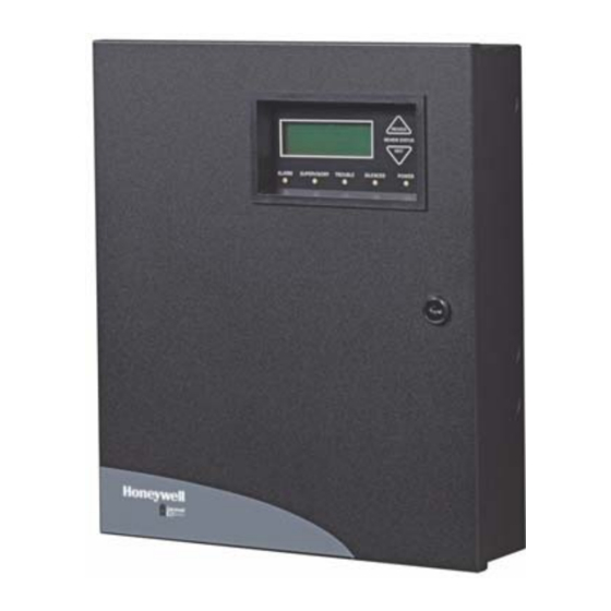
Section 1: Introduction ® The Gamewell-FCI , GWF-7075 is an Addressable Control/Communicator, Fire Alarm Control Panel (FACP) that complies with the UL Standard 864. The GWF-7075 consists of two models. • GWF-7075 (red) cabinet • GWF-7075B (black) cabinet *All references to GWF-7075 within this manual are applicable to the GWF-7075B. 1.1 Overview of Basic System 1.1.1 Hardware Features The GWF-7075 panel includes the following hardware features. -
Page 9: About This Manual
WAM-MM Wireless Monitor module B210W Wireless 6” (15.23cm) flanged Base Miscellaneous HFSS Honeywell Fire Software For communication and panel programming with a Windows-based computer. Enables Suite remote viewing of detector status and event history. 7860 Telephone Cord RJ31X cord for connecting phone line to the GWF-7075 7628 UL Listed End-of-line resistor. -
Page 10: Section 2: Agency Listings, Approvals, And Standards
Section 2: Agency Listings, Approvals, and Standards CO2 RELEASING APPLICATIONS PRECAUTIONS: WARNING: WHEN USED FOR CO2 RELEASING APPLICATIONS, OBSERVE PROPER PRECAUTIONS AS STATED IN NFPA STANDARD 12. DO NOT ENTER THE PROTECTED SPACE UNLESS PHYSICAL LOCKOUT AND OTHER SAFETY PROCEDURES ARE COMPLETED. DO NOT USE SOFTWARE DISABLE FUNCTIONS IN THE PANEL AS LOCKOUT. 2.1 NFPA, UL and NEC Standards The Manufacturer recommends that the Installer understand the requirements of the Authority Having Jurisdiction (AHJ) and comply with the standards set forth by the following regulatory agencies:... -
Page 11: Federal Communications Commission (Fcc)
• If trouble is experienced with the GWF-7075, for repair or warranty information, please contact Honeywell technical support www.gamewell-fci-essd.com. If the equipment is causing harm to the telephone network, the telephone company may request that you disconnect the GWF-7075 until the problem has been resolved. -
Page 12: Underwriters Laboratories (Ul)
Agency Listings, Approvals, and Standards Underwriters Laboratories (UL) Electrical Safety Advisory: Parties responsible for equipment requiring AC power should consider including an advisory notice in their customer information suggesting the customer use a surge arrestor. Telephone companies report that electrical surges, typically light- ning transients, are very destructive to customer terminal equipment connected to AC power sources. -
Page 13: Section 3: Installation Instructions Criteria
If you have questions about the software and the most recent version for a specific application, contact Technical Support . To download the HFSS Honeywell Fire Software Suite, you must obtain Customer Training from a Certified Trainer is available at www.gamewell-fci.com. -
Page 14: Wiring Specifications
Installation Instructions Criteria Wiring Specifications 3.4 Wiring Specifications Induced noise (transfer of electrical energy from one wire to another) can interfere with telephone communication or cause false alarms. To avoid induced noise, follow these guidelines: • Isolate input wiring from high current output and power wiring. Do not pull the one multi-conductor cable for the entire panel. Instead, separate the wiring as follows: High voltage AC power Terminals... -
Page 15: Board Assembly Diagram
Installation Instructions Criteria Board Assembly Diagram 3.5 Board Assembly Diagram On-board Annunciator AC Power Input 120 VAC, 60 Hz, 1.5A Program Port Battery Connector Phone Lines SLC In/Out, NAC/Aux Form C SLC Programming Power Circuits Trouble Relay SBUS Connections Figure 3.2 Model GWF-7075 Assembly Figure 3.2 shows the circuit boards, and annunciator. -
Page 16: 2: Current Draw Worksheet For Velociti Slc Devices
Installation Instructions Criteria Calculating Current Draw and Standby Battery 3.6.2 Current Draw Worksheet for Velociti SLC Devices Use Table 3.3 to determine current requirements during alarm/battery standby operation when Velociti SLC devices are installed. You can install up to 75 Velociti detectors and 75 Velociti modules Number of Standby Alarm... - Page 17 Installation Instructions Criteria Calculating Current Draw and Standby Battery Number of Standby Alarm Device Current per Device Devices Current Current Standby: .5mA mA B200S Intelligent Sounder Base Aux Pwr Alarm: (high vol) 35mA Standby .3mA mA SLC Accessories B200SR-LF Low Frequency Sounder Base Aux Pwr Standby: 1mA mA...
-
Page 18: 3: Maximum Battery Standby Load
Installation Instructions Criteria Calculating Current Draw and Standby Battery 3.6.3 Maximum Battery Standby Load The table below shows the maximum battery standby load allowed to power the GWF-7075 based on 24 and 60 hours of standby power. The standby load calculations of line D in the Current Draw Calculation Worksheet (Table 3.4) must be less than the number shown in the table below for the battery size used and standby hours required. -
Page 19: Section 4: Control Panel Installation
Section 4: Control Panel Installation CAUTION: TO AVOID THE RISK OF ELECTRICAL SHOCK AND DAMAGE TO THE UNIT, BEFORE YOU INSTALL OR SERVICE THE FIRE ALARM CONTROL PANEL, SHUT-OFF ALL POWER. 4.1 Mounting the Control Panel Cabinet Before you mount the GWF-7075 panel, read the environmental 12.531"... -
Page 20: Battery Power
Control Panel Installation Battery Power 4.3 Battery Power Before you connect the batteries to the fire alarm control panel, make certain that the interconnect cable between the batteries is not con- nected and be sure the following conditions exist before you connect the batteries. •... -
Page 21: Sbus Wiring
Control Panel Installation SBUS Wiring 4.4 SBUS Wiring This section contains information on calculating SBUS wire distances and the types of wiring configurations (Class B). 4.4.1 Procedure to Calculate the Wiring Distance for SBUS Modules To determine the type of wire and the maximum wiring distance that you can use with the fire alarm control panel SBUS accessory mod- ules, refer to the following instructions. -
Page 22: 2: Wiring Configurations
Control Panel Installation RA-1000 Remote Annunciator Installation 4.4.2 Wiring Configurations Figure 4.7 illustrates Class B configuration. supervised power limited Figure 4.7 SBUS Class B Wiring 4.4.3 Procedure to Power SBUS Devices from an Auxiliary Power Supply Figure 4.8 illustrates how to power SBUS devices from an Auxiliary Power Supply such as, the GFPS-6 or GFPS-9, when the maximum number of SBUS devices exceeds the SBUS power requirements. -
Page 23: 1: Mounting The Ra-1000
Control Panel Installation RA-1000 Remote Annunciator Installation 4.5.1 Mounting the RA-1000 This section of the manual describes mounting the remote annunciator. The annunciator can be flush- or surface-mounted. Figure 4.10 shows the parts of the annunciator. Instructions for disassembling and mounting appear on the following pages. Back Box Electronic Assembly (Front View) - Page 24 Control Panel Installation RA-1000 Remote Annunciator Installation Flush Mounting Installation Instructions To install a flush mount, do the following: Cut a hole in the sheet rock to the following dimensions: 8-1/4” W x 6-5/8” H. If you use an electrical box, the box must be 1-3/8” set back from the face of the wall to accommodate the annunciator (see Figure 4.12).
-
Page 25: 5824 Serial/Parallel Printer Interface Module Installation
Control Panel Installation 5824 Serial/Parallel Printer Interface Module Installation 4.6 5824 Serial/Parallel Printer Interface Module Installation You can use the 5824 Serial/Parallel Printer Interface Module to connect a printer to the panel. Printing is available for real-time events, detector status and event history. To install the 5824 Serial/Parallel Printer module, do the following steps: Make sure power is off at the panel. -
Page 26: 5880 Led Driver Module
Control Panel Installation 5880 LED Driver Module 4.7 5880 LED Driver Module The 5880 is an LED driver board that can be used in a wide variety of applications, including as an interface with most customized floor plan annunciator boards. The 5880 can drive up to 40 LEDs and has one PZT controller. The 5880 also has eight inputs for dry contact monitoring. -
Page 27: 3: Led Wiring
Control Panel Installation 5880 LED Driver Module 4.7.3 LED Wiring To connect the LEDs, use the four 12-pin connectors on the 5880 board. Each LED gets its power from Pin 11. Internal resistors are sized so that there is approximately 10 mA of current for each LED, no series resistors are required. LED outputs can be mapped to out- put circuits. -
Page 28: Configuring Modules
4.9 Telephone Connection Connect the telephone lines as shown in Figure 4.22. The Model 7860 phone cord is available from Honeywell for this purpose. A number of programmable options are available so that you can customize the telephone lines. These options are described in Section 7.6. -
Page 29: Notification Appliance/Auxiliary Power Circuits
Control Panel Installation Notification Appliance/Auxiliary Power Circuits 4.10 Notification Appliance/Auxiliary Power Circuits Two outputs are built-in to the GWF-7075 FACP which can be programmed to be used as NACs (Class A or Class B) or as Aux power. This section of the manual explains how to do the following: •... -
Page 30: 2: Auxiliary Power Installation
Control Panel Installation On-Board Relays (Conventional) 4.10.2 Auxiliary Power Installation NAC Circuits 1and 2 on the control panel can be used as auxiliary power circuits. The four types of auxiliary power available are: • Door Holder • Constant • Resettable Power •... -
Page 31: Remote Station Applications
Control Panel Installation Remote Station Applications 4.12 Remote Station Applications 4.12.1 Keltron Model 3158 Installation The fire alarm control panel is compatible with the Keltron Model 3158, used for direct connection to a Keltron receiver. The Keltron 3158 reports alarms, supervisories, and troubles. The Keltron 3158 is intended for connection to a polarity reversal circuit of a remote station receiving unit with compatible ratings. -
Page 32: 3: Nfpa 72 Polarity Reversal
Control Panel Installation Remote Station Applications 4.12.3 NFPA 72 Polarity Reversal Using the 5220 Module When you wire and program the 5220 Module for polarity reversal, it reports alarm and trouble events to a remote site. Alarms will over- ride trouble conditions and it will not be possible to reset the remote indicator until you clear the condition and reset the control panel. If an alarm condition occurs, the alarm relay will close, overriding the trouble condition. -
Page 33: 4: Using A Mr-201/T Control Relay From Air Products
Control Panel Installation Remote Station Applications 4.12.4 Using a MR-201/T Control Relay From Air Products When the MR-201/T control relay is wired for polarity reversal, it reports alarm and trouble events to a remote site. Alarms will override trouble conditions and it will not be possible to reset the remote indicator until the condition is cleared and the control panel is reset. If an alarm condition occurs, the alarm relay will close, overriding the trouble condition. -
Page 34: Section 5: Velociti® And Swift™ Slc Device Installation
® ™ Section 5: Velociti and SWIFT SLC Device Installation CAUTION: To avoid the risk of electrical shock and damage to the unit, turn off the power at the control panel, when you install or service the panel. 5.1 List of Velociti SLC Devices The following Velociti mode SLC devices can be used with the control panel. -
Page 35: Wiring Requirements For Slc Devices
Velociti® and SWIFT™ SLC Device Installation Wiring Requirements for SLC Devices 5.4 Wiring Requirements for SLC Devices The following information applies to SLC devices. Refer to the section that describes the type of device you are installing for details. 5.4.1 Wire Sizing for Internal SLC The SLC requires use of a specific wire type, depending on mode of operation, to ensure proper circuit functioning. -
Page 36: 2: Wiring Slc In Class A Configuration
Velociti® and SWIFT™ SLC Device Installation Velociti Detector Installation 5.4.2 Wiring SLC in Class A Configuration Figure 5.3 illustrates how to wire the SLC loop for Class A installations. NOTE: Class A does not use short circuit isolator devices. Class X requires an isolator module as the first device on the in and the out loop.There are No t-taps allowed on the Class A SLC loops. -
Page 37: Addressing Velociti Slc Devices
Velociti® and SWIFT™ SLC Device Installation Addressing Velociti SLC Devices 5.7 Addressing Velociti SLC Devices All Velociti devices are addressed using the two rotary dials that appear on the device board. Use the ONES rotary dial to set the ones place in a one or two digit number, and use the TENS rotary dial to set the tens place in a two digit number. -
Page 38: Section 6: Programming Overview
Section 6: Programming Overview This section of the manual is intended to give you an overview of the programming process. Please read this section of the manual care- fully, especially if you are programming the control panel for the first time. ®... -
Page 39: Mapping Overview
Events and to Output Special Groups Only System Figure 6.1 Mapping Overview NOTE: Mapping cannot be programmed through annunciators and can only be programmed through HFSS Honeywell Fire Software Suite. GWF-7075 Addressable Fire Alarm Control Panel Manual — P/N LS10147-002GF-E:E 06/11/2019... -
Page 40: 1: Input Point Mapping
Programming Overview Mapping Overview 6.2.1 Input Point Mapping 6.2.2 Output Circuit Mapping Input Points are assigned to input zones. Any input point can be Figure 6.3 is a simple example showing how to assign notification assigned to any input zone. (Input points can be assigned to one and relay output circuits to groups. - Page 41 Programming Overview Mapping Overview Figure 6.5 illustrates the Example of zone events mapped to output groups and patterns. Zone 4 Zone 4 Group 4 Storage Storage Floor 4 Group 4 Floor 4 Floor 4 Notification Floor 4 Notification Zone 3 Zone 3 Group 3 Offices...
-
Page 42: Mapping Led Points
6.4 Programming Using the HFSS Software Suite You can use the HFSS Honeywell Fire Software Suite to program the control panel onsite (personnel will need to be onsite during the upload or download process). HFSS is a software package that lets you easily program the control panel using a Windows-based com- puter. -
Page 43: 2: Using The Menus
Programming Overview Programming Using an Annunciator 6.5.2 Using the Menus Figure 6.7 shows how to move through Menu screens, using the System Tests screen as an example. Figure 6.7 Using the Program Menu 6.5.3 Selecting Menu Options and Entering Data There are several ways to make programming selections using the control panel depending on which screen you are currently using. -
Page 44: Programming Menu Quick Reference
Programming Overview Programming Menu Quick Reference 6.6 Programming Menu Quick Reference This section of the manual lists all Program Menu options in the order they appear on the sub-menus. In the Options/Defaults column, Default settings are indicated in text or marked with an asterisk. The Comments column provide quick information and a reference to a section (if applicable) which includes more detailed information. - Page 45 Programming Overview Programming Menu Quick Reference Menu Options/Defaults Comments STATUS POINT CO DETECTOR SWITCH LATCH CO SUPERVISORY DETECTOR SWITCH NON-LATCH Section 7.5.1 OUTPUT PT Select Group 1,2,3 AUX CONST NOTIF AUX RESET AUX DOOR Velociti Devices on Enter Point Select Group 1,2,3 Point RELAY...
- Page 46 Programming Overview Programming Menu Quick Reference Menu Options/Defaults Comments Point Internal Power and Point # Section 7.5.1 (cont.) External Power No Accessory SDR BAS RLY BAS CO SUPR/FIRE SUPR I-SdrBA (Intelligent Sounder Base) Photo 1,2,3,5 Acclimate 1,2,4 W-Detector Heat 1,2,4 W-SUP DET Same as W-Detector UNUSED...
- Page 47 Programming Overview Programming Menu Quick Reference Menu Options/Defaults Comments System Communication Phone Lines For each phone line (1 & 2) select: Options Options Dialing Prefix Up to 9 digits *none # of Answer Rings Range: 00-15 Select Dialing Option TT/PL PULSE U = 60/40 Rotary Pulse Format...
-
Page 48: Section 7: Programming
Section 7: Programming To manually program the control panel from the built-in annunciator. Each subsection discusses these menu options in detail. All options described in this section can be performed using the HFSS Honeywell Fire Software Suite. IMPORTANT! ® Before you complete any customized programming, you must first run JumpStart Auto-programming. -
Page 49: 4: Changing Module Options
Programming Modules 7.2.4 Changing Module Options Each module has a unique set of options that specifically applies to the functionality of the module you edit. Use the <Right> arrow key to move the cursor between available options. To edit the Option settings, press the <Up> or <Down> arrows. 7.2.5 Adding a Module You must access the Main Menu to add a Module. - Page 50 The programmed Zone Type is provided for user reference only. To modify the Zone Type, use the HFSS Honeywell Fire Software Suite Software Suite. Table 7.2 list the Alarm Delay choices and a description of each. Then press <Enter>.
-
Page 51: 12: Zone Accessory Options
Programming Modules 7.2.12 Zone Accessory Options Do steps 1 through 5 of Section 7.2.9. Press 3 to edit the Zone’s Accessory options. Single or Multi-Station Cadence Pattern (choose from Patterns 00 to 02, 23 if you are using Velociti. Choose from 00-16, 23 is using SD devices). See Appendix C. CO Single and Multi-station Cadence (choose from Cadence Patterns 00 to 02, 23 for Velociti devices). -
Page 52: 18: View Group Points
Programming Point 7.2.18 View Group Points Enter the Installer Code. The panel will automatically access the Main Menu. Select 7 for the Panel Programming. Press 3 to enter the Group Menu. Press 2 to view the Group Points. Enter the Group Number, then press <Enter>. Figure 7.5 View Group Points 7.2.19 Edit OPG Template Enter the Installer Code. - Page 53 Programming Point Type Function Latching Option Comments Selection SWITCH WATERFLOW Latching Use this switch type for monitoring water flow in a sprinkler system. Switch Non Latching closure will cause a sprinkler alarm. Water Flow switches can be programmed as latching or non-latching. You can program a delay of up to 90 seconds to be used with a Water Flow Switch.
-
Page 54: 2: Point Programming For An Internal Or An External Power Module
Programming Point 7.3.2 Point Programming for an Internal or an External Power Module To program for an internal or external Power Module Points, follow these steps: Enter the Installer Code. Select 7 for the Program Menu. Press 4 to enter the Point Menu. Press the <Up>... -
Page 55: System Options
Programming System Options 7.3.3 Point Programming for 5880 Modules To program for a 5880 Module points, follow these steps: Enter the Installer Code. Select 7 for the Program Menu. Press 4 to enter the Point Menu. Press the <Up> or <Down> arrows to select the desired module. Refer to Section 6.5 for available choices. Press <Enter>. Enter the Point Number, then press <Enter>. - Page 56 Enter a Dialing Prefix (if needed), then press <Enter>. Or, Press the <Right> arrow to bypass the Dialing Prefix option. Number of Answer Rings Use this option in conjunction with the HFSS Honeywell Fire Software Suite to define the number of rings that occur before the panel answers a call from the computer.
- Page 57 Programming System Options AlarmNet Timers Enter the Installer Code. The control panel will automatically access the Main Menu. Select 7 for Panel Programming. Select 5 for System Options. From the next menu, select 1 for Communication Options. Select 4 for AlarmNet Timers. The available options for AlarmNet Timers are as follows •...
-
Page 58: 3: Holiday Days
Programming System Options 7.4.3 Holiday Days Up to 18 dates can be designated as holidays. When day/night sensitivity is enabled, all photoelectric smoke detectors in the system will use night sensitivity for the entire day on days designated as holidays (see Section 7.4.3). To add or change a holiday, follow these steps. -
Page 59: 5: Miscellaneous Options
Programming System Options AC Report Delay NOTE 1: You must select 1-3 hours in UL Central Station installations and UL Remote Signaling installations. You can adjust the number of hours before a Low AC Report will be sent to the Central Station. To program Low AC Report Delay, follow these steps: NOTE 2: Steps continued from step 7 of subsection, Alarm Verify. -
Page 60: 7: Slc Family
Programming System Options Daylight Saving Time Start and End Use the Daylight Saving Time Start and End option to adjust the week and month Daylight Saving Time (DST) starts and ends. For this feature to work, you must enable (set to Yes) the Automatic Daylight Savings Adjustment option under Daylight Savings Options. The default values for the DST Start and End are as follows: DST Start: ... -
Page 61: Section 8: System Operation
Section 8: System Operation To operate the fire alarm control panel, use the Menus. The Menus provide step-by-step procedures to set-up the System Operations. This section of the manual is an overview of the System Operation Menus. Please read this entire section carefully before operating the panel. -
Page 62: Basic Operation
Events to make room for the new Events as they occur. When you view the Event History in the panel, the most recent 500 Events from every panel in the site display. When you use the HFSS Honeywell Fire Software Suite, the System will upload all 1000 Events from every panel in the network. -
Page 63: 6: Conduct A Communicator Test
A screen similar to those shown in Figure 8.3 will display. You can print detector status by uploading the detector status to and printing from HFSS Honeywell Fire Software Suite. GWF-7075 Addressable Fire Alarm Control Panel Manual — P/N LS10147-002GF-E:E 06/11/2019... -
Page 64: 11: View Status Of A Point
System Operation Basic Operation Example of a Non-Compliant Detector Example of Compliant Detector Blanks signify a Non- Detector ID Indicates percent Compliant Detector. Fields obscurity per foot. To access Next SMOKE ION --------% SMOKE ION 1.1% Display, press MODULE_33 POINT_4 MODULE_33 OINT_4 <Right Arrow>. -
Page 65: Operation Mode Behavior
System Operation Operation Mode Behavior Ethernet Information Press 5 from the System Information Menu for Ethernet Information. Figure 8.4 Ethernet Information AlarmNet Info Press 6 from the System Information Menu for AlarmNet Info Cell Strength: 0 to 100% Status: Registered/Not Registered. AlarmNet Temp Pin Press 7 from the System Information Menu for AlarmNet Temp Pin. -
Page 66: Operation Mode Behavior Conditions
System Operation Operation Mode Behavior Conditions 8.6 Operation Mode Behavior Conditions The control panel can be in one of the following seven conditions at any given moment: • Normal • Alarm • Pre-alarm • Supervisory • Trouble • Silenced • Reset Table 8.4 describes the behavior of the panel in each of these modes. - Page 67 System Operation Operation Mode Behavior Conditions Operation Operation Mode Operation Mode Troubleshooting System Behavior Mode Condition Options The communicator seizes control of the phone Press the down arrow to view the alarm. A line and calls the central station. screen similar to this one displays. The on-board annunciator sounds a loud, steady beep (any notification devices attached to the system will also sound).
-
Page 68: Releasing Operations
System Operation Releasing Operations Operation Operation Mode Operation Mode Troubleshooting System Behavior Mode Condition Options The communicator seizes control of the phone Press down arrow to view the trouble. A screen line and calls the central station. similar to this one displays. The on-board annunciator sounds a loud, pulsing beep in the sequence one second on, nine seconds off. -
Page 69: 1: Single Interlock Zone Releasing
System Operation Releasing Operations NOTE 3: The Installer must define which input points to use for detectors, manual release switches, or interlock/pressure switches. NOTE 4: For a list of compatible and approved releasing solenoids, refer to the Compatibility Addendum for Gamewell-FCI Manuals, P/N:9000-0427-L8. -
Page 70: Smoke Alarm Verification
System Operation Smoke Alarm Verification 8.7.2 Double Interlock Zone Releasing A Double Interlock Zone uses a minimum of two Addressable detectors, a designated manual release switch, and an interlock switch input. In this document, an interlock switch is typically a dry-contact pressure switch and is referred to as an interlock/pressure switch. WARNING: ONLY ADDRESSABLE DETECTORS CAN BE USED. -
Page 71: Section 9: Reporting
Manufacturer Model Format Silent Knight by Model 9800 SIA and Contact ID Honeywell Model 9000 (SIA formats) Honeywell Security AlarmNet 7810-ir IP and Cellular Receiver, Contact ID only Ademco MX8000 SIA and Contact ID Ademco Model 685 (Contact ID ) - Page 72 Reporting Receivers Compatible with the Control Panel SIA Reporting Format Contact ID Reporting Format SIA pi Modifier Event Description Module ID Parameter Fixed Length Qualifier Event Group # Contact # # (If Any) Event Format NN - panel Code Codes XX- SBUS ID ZZZ- Zone # PPPP- Point #...
- Page 73 Reporting Receivers Compatible with the Control Panel SIA Reporting Format Contact ID Reporting Format SIA pi Modifier Event Description Module ID Parameter Fixed Length Qualifier Event Group # Contact # # (If Any) Event Format NN - panel Code Codes XX- SBUS ID ZZZ- Zone # PPPP- Point #...
- Page 74 Reporting Receivers Compatible with the Control Panel SIA Reporting Format Contact ID Reporting Format SIA pi Modifier Event Description Module ID Parameter Fixed Length Qualifier Event Group # Contact # # (If Any) Event Format NN - panel Code Codes XX- SBUS ID ZZZ- Zone # PPPP- Point #...
- Page 75 Reporting Receivers Compatible with the Control Panel SIA Reporting Format Contact ID Reporting Format SIA pi Modifier Event Description Module ID Parameter Fixed Length Qualifier Event Group # Contact # # (If Any) Event Format NN - panel Code Codes XX- SBUS ID ZZZ- Zone # PPPP- Point #...
- Page 76 Reporting Receivers Compatible with the Control Panel SIA Reporting Format Contact ID Reporting Format SIA pi Modifier Event Description Module ID Parameter Fixed Length Qualifier Event Group # Contact # # (If Any) Event Format NN - panel Code Codes XX- SBUS ID ZZZ- Zone # PPPP- Point #...
- Page 77 Reporting Receivers Compatible with the Control Panel SIA Reporting Format Contact ID Reporting Format SIA pi Modifier Event Description Module ID Parameter Fixed Length Qualifier Event Group # Contact # # (If Any) Event Format NN - panel Code Codes XX- SBUS ID ZZZ- Zone # PPPP- Point #...
- Page 78 Reporting Receivers Compatible with the Control Panel SIA Reporting Format Contact ID Reporting Format SIA pi Modifier Event Description Module ID Parameter Fixed Length Qualifier Event Group # Contact # # (If Any) Event Format NN - panel Code Codes XX- SBUS ID ZZZ- Zone # PPPP- Point #...
- Page 79 Reporting Receivers Compatible with the Control Panel SIA Reporting Format Contact ID Reporting Format SIA pi Modifier Event Description Module ID Parameter Fixed Length Qualifier Event Group # Contact # # (If Any) Event Format NN - panel Code Codes XX- SBUS ID ZZZ- Zone # PPPP- Point #...
-
Page 80: Section 10: Testing And Troubleshooting
Section 10: Testing and Troubleshooting 10.1 Troubleshooting This section of the manual offers suggestions for troubleshooting hardware problems. Please read this section if you encounter a problem when installing the control panel. If these suggestions do not solve your problem or if you encounter a problem that is not listed here, contact Gamewell-FCI Technical Support for assistance. -
Page 81: 4: Slc Device Locator
Testing and Troubleshooting Earth Fault Resistance 10.2.4 SLC Device Locator SLC device locator can be used to locate a device on a SLC loop. Follow these steps to locate a particular SLC device: Select 2 (Point Functions) from the Main Menu. Select 4 (SLC Dev Locator). -
Page 82: Section 11: Installation Records
Section 11: Installation Records 11.1 Velociti SLC Device Point Record You can use Table 11.1 to keep track of Velociti SLC detectors and modules. Default addresses for ID: On-board: = 97 Zone / Zone/ Detector Addr Description Detector Addr Description Group Group On-board 1... -
Page 83: Section 12: Installation Records
Installation Records Velociti SLC Device Point Record Section 12: Installation Records 12.1 Velociti SLC Device Point Record You can use Table 12.1 to keep track of Velociti SLC detectors and modules. Default addresses for ID: On-board: = 97 Detector Address Zone / Group Description Detector Address Zone/ Group Description... -
Page 84: Appendix A: Using The Built-In Programmer To Edit Text
Using the Built-In Programmer to Edit Text Characters Used to Edit Text Appendix A: Using the Built-In Programmer to Edit Text This section contains tables of programmable characters that you can use for the following labels: • • • device site group •... -
Page 85: Appendix B: Cadence Patterns
Cadence Patterns Appendix B: Cadence Patterns The cadence patterns shown in Appendix B: are available for use with the control panel. Figure B.1 Cadence Patterns GWF-7075 Addressable Fire Alarm Control Panel Manual — P/N LS10147-002GF-E:E 06/11/2019... -
Page 86: Appendix C: Expanded Receiver/Panel Relationship
Expanded Receiver/Panel Relationship Appendix C: Expanded Receiver/Panel Relationship The available Receiver Number will correspond with the Panel Number that you entered. Receiver Numbers are populated based on the Panel Number and it is audited to allow only the four appro- priate Receivers. - Page 87 Manufacturer Warranties and Limitation of Liability Manufacturer Warranties. Subject to the limitations set forth herein, Manufacturer warrants that the Products manufactured by it in its Northford, Connecticut facility and sold by it to its authorized Distributors shall be free, under normal use and service, from defects in material and workmanship for a period of thirty six months (36) months from the date of manufacture (effective Jan.
- Page 88 Honeywell Gamewell-FCI 12 Clintonville Road Northford, CT 06472-1610 203.484.7161 LS10147-002GF-E | E | 06-2020 www.gamewell-fci.com ©2020 Honeywell International Inc.