Table of Contents
Advertisement
Quick Links
Installer's Guide
Variable Speed - Communicating Air Handlers
with Integrated Whole House Air Cleaner
4TEE3D01B1000A,
4TEE3D02B1000A,
4TEE3D03B1000A,
WARNING:
ALL phases of this installation must comply with NATIONAL, STATE AND LOCAL CODES
IMPORTANT - This Document is customer property and is to remain with this unit. Please return to service information
pack upon completion of work.
This Air Handler can be configured for Communicating
or 24 VAC modes. Using fully Communicating or 24
VAC modes, the Air Handler can support multi stage
heat pump, multi stage cooling only, or multi stage cool-
ing with electric heat applications. This unit is equipped
with an integrated high efficiency Whole House Air
Cleaner. Careful consideration must be taken in the in-
stallation process to avoid personal injury or equipment
damage.
▲
WARNING
!
SAFETY HAZARD!
THIS INFORMATION IS FOR USE BY INDIVIDUALS
HAVING ADEQUATE BACKGROUNDS OF ELECTRICAL
AND MECHANICAL EXPERIENCE. ANY ATTEMPT TO
REPAIR A CENTRAL AIR CONDITIONING PRODUCT
MAY RESULT IN PERSONAL INJURY AND/OR PROP-
ERTY DAMAGE. THE MANUFACTURER OR SELLER
CANNOT BE RESPONSIBLE FOR THE INTERPRETA-
TION OF THIS INFORMATION, NOR CAN IT ASSUME
ANY LIABILITY IN CONNECTION WITH ITS USE.
▲
CAUTION
!
EQUIPMENT DAMAGE!
TO PREVENT SHORTENING ITS SERVICE LIFE, THE
AIR HANDLER SHOULD NOT BE USED DURING THE
FINISHING PHASES OF CONSTRUCTION OR REMOD-
ELING. The low return air temperatures can lead to the
formation of condensate. Condensate in the presence
of chlorides and fluorides from paint, varnish, stains,
adhesives, cleaning compounds, and cement creates a
corrosive condition which may cause rapid deteriora-
tion of the cabinet and internal components.
A. GENERAL INFORMATION
These instructions do not cover all variations in sys-
tems or provide for every possible contingency. Should
further information be desired or particular issues arise
which are not covered sufficiently by this manual, con-
tact your local distributor or the manufacturer as listed
on the Air Handler nameplate.
These Air Handlers are shipped from the factory in the
upflow or horizontal right configuration.
© 2008 Trane
4TEE3D04B1000A,
4TEE3D05B1000A,
4TEE3D06B1000A,
HAZARDOUS VOLTAGE - DISCONNECT POWER BEFORE SERVICING
4TEE3D07B1000A,
4TEE3D08B1000A,
4TEE3D09B1000A,
CONTENTS
General Information ....................................................... 1
Installation Limitations & Recommendations ............................ 2
Two Piece Cabinet Disassembly ................................... 4
Unit Installation .............................................................. 4
Vertical Upflow ......................................................................... 4
Horizontal Right ....................................................................... 9
Duct Connections .......................................................... 10
Refrigerant Piping ........................................................ 10
Brazing to Evaporator Section .................................... 10
Condensate Drain Piping .............................................. 11
Electrical - Power Wiring .............................................. 12
Control Wiring ................................................................ 12
Airflow Adjustment ....................................................... 13
Unit Test Mode ................................................................ 13
User Interface Menus ..................................................... 14
Air Handler Flash Codes ............................................... 17
Field Wiring ..................................................................... 18
Outline Drawing ............................................................. 20
Maintenance .................................................................... 22
Cleaning the Collection Cell .................................................. 22
Cleaning the Field Charger .................................................... 23
Checkout Procedures .................................................... 24
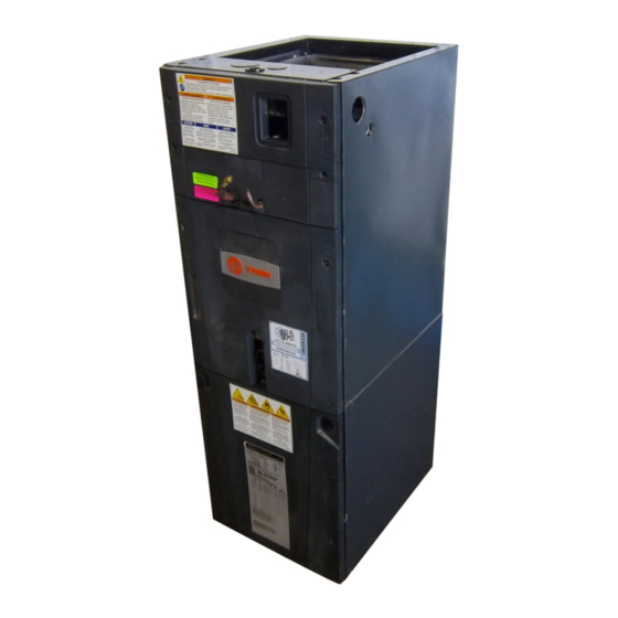
NOTE: Representative illustrations only - actual models
may vary.
INSPECTION
Check carefully for any shipping damage. This must be
reported to and claims made against the transportation
company immediately. Check to be sure all major compo-
nents are in the unit. Any missing parts should be reported to
your supplier at once, and replaced with authorized parts
only. See Figure 2 for air cleaner
18-GE15D1-2
4TEE3D10B1000A
parts.
Advertisement
Table of Contents

Related Manuals for Trane 4TEE3D01B1000A


Summary of Contents for Trane 4TEE3D01B1000A
-
Page 1: Table Of Contents
Any missing parts should be reported to These Air Handlers are shipped from the factory in the your supplier at once, and replaced with authorized parts upflow or horizontal right configuration. parts. only. See Figure 2 for air cleaner © 2008 Trane... -
Page 2: Installation Limitations & Recommendations
HEATER IS AVAILABLE FROM THE DEALER. ONLY 6. Penetration around the Refrigerant lines must be HEATERS BUILT BY TRANE ARE APPROVED FOR USE sealed and Electrical inlets need to be sealed at both IN THE AIR HANDLER. These heaters have been de- the Low and the High Voltage. - Page 3 Installer’s Guide 16. If side, front or rear return is required, Air Handler must Steam and Flow-through Fan Power Duct-mounted be elevated or placed on a plenum [TAYPLNM100 for Humidifiers. Follow the humidifier installation instruc- 4TEE3D02, 03, 04, 06, & 08 (23.5" wide), TAYPLNM101 tions.
-
Page 4: Two Piece Cabinet Disassembly
Installer’s Guide B. TWO PIECE CABINET DISASSEMBLY C. UNIT INSTALLATION (OPTIONAL) ▲ ▲ CAUTION NOTE: For easier installation into tight areas, the When installing the narrow coil baffle, make sure to 4TEE3D03, 04, 06, 08, 09, & 4TEE3D10B air handlers can align the baffle up with the holes so NOT to puncture be disassembled, moved to an attic or other space, and the coil tubing. - Page 5 Installer’s Guide 4. The horizontal drip tray should be removed for maximum efficiency. See Figures 9, 10, and 11. a. Remove the coil by sliding it out on the coil channel supports. For the 4TEE3D05, 07, 09, & 10 units, there is a coil support tab at the top of the coil, connected to the case, that must be removed first.
- Page 6 Installer’s Guide 9. Sheetmetal screws CANNOT be used to attach the return ductwork on the side of the unit. 10. Pedestal and unit should be isolated from the foun- dation using a suitable isolating material. 11. Openings where field wiring enters the cabi- net must be completely sealed.
-
Page 7: Horizontal Right
Installer’s Guide UPFLOW COLLECTION Electrical Contacts Electrical Contacts FIELD CHARGER CELL Actuator Tab HORIZONTAL RIGHT Electrical Contacts Actuator Tab Electrical Contacts COLLECTION FIELD CELL CHARGER Figure 14. COLLECTION CELL AND Field Charger Orientations 18-GE15D1-2... - Page 8 Installer’s Guide DOWNFLOW COLLECTION FIELD CELL CHARGER Electrical Contacts Electrical Contacts Actuator HORIZONTAL LEFT COLLECTION FIELD CELL CHARGER Actuator Tab Electrical Contacts Electrical Contacts on Bottom side on Bottom side on Bottom side Downflow and Horizontal Left orientations available with application of Downflow kit provided in Accessory Kit. Figure 15.
- Page 9 Installer’s Guide HORIZONTAL RIGHT Unit is shipped from the factory in the horizontal right configuration. Unit conversion is not re- quired. If the unit is suspended, it must be supported from the bottom near both ends as well as the middle to prevent sagging.
-
Page 10: Duct Connections
Installer’s Guide D. DUCT CONNECTIONS The supply and return air ducts should be connected to the unit with flame retardant duct connectors. Convert- ible duct flanges are provided on the discharge opening to provide a “flush fit” for 3/4" or 1-1/2" duct board appli- cations, see the Outline drawing on page 21 for sizes of the duct connections. -
Page 11: Condensate Drain Piping
Installer’s Guide EZT-105 2" MINIMUM 2" MINIMUM Figure 21. Manufactured Traps Figure 19. Braze Shield CAP OR PLUG G. CONDENSATE DRAIN PIPING 2" MIN. 2" MIN. NOTE: Make certain that the unit has been installed in a level position to ensure proper draining. 2"... -
Page 12: Electrical - Power Wiring
Installer’s Guide NOTE: If Air Handler is used with or without a heater, 7. Provide means for drainage to prevent winter the electrical entry hole as well as any other cabinet freeze-up of condensate line. penetrations must be sealed air tight. 8. -
Page 13: Airflow Adjustment
Installer’s Guide J. AIRFLOW ADJUSTMENT K. UNIT TEST MODE Unit Test Mode (Air Handler) Blower speed changes are made using the User Inter- The system must be idle or the comfort control face mounted on the communicating Comfort Control switched to OFF before the Unit Test will run the air box. - Page 14 Installer’s Guide USER INTERFACE MENU - COMMUNICATING MODE Figure 24. User Interface Menu - Communicating Mode 18-GE15D1-2...
- Page 15 Installer’s Guide USER INTERFACE MENU- 24 VAC MODE Figure 25. User Interface Menu - 24V Mode 18-GE15D1-2...
-
Page 16: User Interface Menus
Installer’s Guide L. AIR HANDLER FLASH CODES Alert Notification Alert Comfort Alert Group Alert Description User Interface Code Fault LED COMM LED Control Display Display Solid ON ‡ CNTRL FAULT † ERR 18 Control Failure Internal Control Error Solid ON ‡ CHECK FUSE †... -
Page 17: Field Wiring
Installer’s Guide M. FIELD WIRING - REFERENCE ONLY COMMUNICATING INDOOR UNIT WITH COMMUNICATING COMFORT CONTROL & COMMUNICATING OUTDOOR UNIT COMMUNICATING INDOOR UNIT WITH COMMUNICATING COMFORT CONTROL & 24 VAC SINGLE STAGE COOLING 18-GE15D1-2... - Page 18 Installer’s Guide COMMUNICATING INDOOR UNIT WITH 24 VAC COMFORT CONTROL & 24 VAC SINGLE STAGE COOLING COMMUNICATING INDOOR UNIT WITH 24 VAC COMFORT CONTROL & 24 VAC 2-STAGE OR 2-STEP COOLING 18-GE15D1-2...
- Page 19 Installer’s Guide COMMUNICATING INDOOR UNIT WITH 24 VAC COMFORT CONTROL & 24 VAC SINGLE STAGE HEAT PUMP COMMUNICATING INDOOR UNIT WITH 24 VAC COMFORT CONTROL & 24 VAC 2-STAGE OR 2-STEP HEAT PUMP 18-GE15D1-2...
-
Page 20: Outline Drawing
Installer’s Guide N. OUTLINE DRAWING FOR 4TEE3D01-10 Printed from D802612REV03 18-GE15D1-2... - Page 21 Installer’s Guide 4TEE3D01-10 AIR HANDLERS DIMENSIONAL DATA 4TEE3D03, 04, 06, 08, 09 & 10A are two piece cabinets Model No. 21.0" 4TEE3D01A1000A 43.00 21.50 4TEE3D02A1000A 45.00 23.50 4TEE3D03A1000A 57.90 23.50 4TEE3D04A1000A 57.90 23.50 4TEE3D05A1000A 51.75 26.00 4TEE3D06A1000A 57.90 23.50 4TEE3D07A1000A 57.90 26.00 4TEE3D08A1000A...
-
Page 22: Integrated Whole House Cleaner Maintenance
Installer’s Guide P. INTEGRATED WHOLE HOUSE AIR CLEANER MAINTENANCE 24 VAC Hot 24 VAC Common Blue 1. For maximum efficiency the COLLECTION CELL should be inspected and cleaned on a regular basis. NOTE: A 30 to 90 day cleaning interval is normal for the Return from air cleaner COLLECTION CELL and should be adjusted based upon Green... -
Page 23: Cleaning The Field Charger
Installer’s Guide R. CLEANING THE FIELD CHARGER 1. Turn the air conditioning system to OFF at the Comfort Control. Loosen thumbscrews to remove the filter panel. Remove the COLLECTION CELL by pulling forward. See Figure 5, page 4. 2. Use a 5/16" nutdriver to remove the screws holding the FIELD CHARGER retainer bracket. - Page 24 4. Check control box panel — in place and secured ..................[ ] NOTE: Operation of heaters must be checked during the operation check of the total system. 10/08 Trane The manufacturer has a policy of continuous product and product data improvement, and it reserves the 6200 Troup Highway right to change design and specifications without notice.