Table of Contents

Related Manuals for Curtis RU Series


Summary of Contents for Curtis RU Series
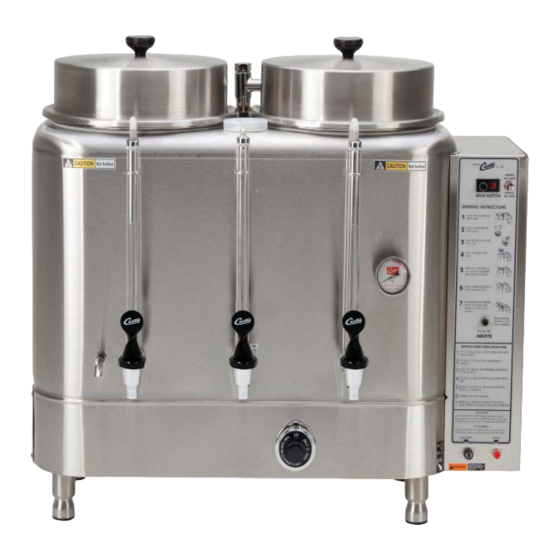
- Page 1 USER GUIDE RU/URN Series Automatic Coffee Urn Style Varies, RU-300 Shown READ AND SAVE THESE INSTRUCTIONS NOTICE TO INSTALLER: Please leave this booklet with the machine. 031022B FC38 - RU AUTOMATIC, FRONT COVER F-10037 revA...
-
Page 2: Table Of Contents
................ES78 .....................................................ES81 ......................ES82 ........................................................................... Contact Information Wilbur Curtis Co., Inc. 6913 Acco Street | Montebello, CA 90640 US Phone: 323-837-2300 | Toll Free: 800-421-6150 Email: csrassistance@wilburcurtis.com | Web: www.wilburcurtis.com . - 4:00 . PT Email: techsupport@wilburcurtis.com... -
Page 3: Fs38
KEY FEATURES/SPECIFICATIONS/SYSTEM REQUIREMENTS FS38 Key Features • Automatic re ll during brew cycle. • Thermostatically controlled for near-instant recovery. • Closed-lid brewing creates superior avor and full coffee aroma. • Swing-spray head evenly saturates coffee grounds for complete extraction. Speci cations (Selected Models) Electrical Supply Requirements MODEL # DESCRIPTION... -
Page 4: Is2
INSTRUCTIONS could result in personal injury or void the warranty. • This appliance is designed for commercial use. Any service other than cleaning and preventive maintenance should be performed by an authorized Wilbur Curtis service technician. • serviceable parts inside. - Page 5 IMPORTANT SAFEGUARDS CE Requirements • This appliance must be installed in locations where it can be overseen by trained personnel. • • This appliance is not suitable for outdoor use. • • • This appliance must not be cleaned by water jet. •...
-
Page 6: Ii2
INSTALLATION INSTRUCTIONS WARNING: WARNING: Improper electrical connection may result in an electric shock hazard or damage the unit. This appliance must be properly grounded. NOTICE: DO NOT connect this appliance to a hot water supply. The water inlet valve is not rated for hot water. -
Page 7: Ii7
INSTALLATION INSTRUCTIONS Installation Prepare the Location WARNING: DO NOT place the urn closer than 6 inches from the wall. The urn must have adequate cross-ventilation. Determine the location. Make sure that the counter is capable of supporting at least 600 lbs. to allow for the urn weight at full capacity. - Page 8 INSTALLATION INSTRUCTIONS Connect the Water Supply Flush the water supply line prior to installation to Back of back of the urn control panel. Leave the water supply valve closed until power is connected. Connect the Wiring WARNING: Turn off power to the junction box at the circuit breaker panel before connecting the power cable to the urn.
- Page 9 IMPORTANT: When operating the unit at elevations above 4000 ft. (1200 m), Curtis recommends that you contact our Technical determine if adjustments to the unit are necessary for your application.
-
Page 10: Oi31
OPERATING INSTRUCTIONS OI31 Brewing Instructions WARNING - TO AVOID SCALDING, AVOID SPLASHING. Keep body parts clear of hot surfaces on the outside of the urn. The urn is factory preset for optimal performance. Thermostat Main power switch The brewer should be Remove the urn lid and rotate Remove the brew basket and the spray arm to the side. - Page 11 OPERATING INSTRUCTIONS OI31 Aeration During brewing, the richer, thicker coffee tends to settle toward the bottom of the liner, while the weaker part of the mixture tends to move to the top. The aeration feature assures uniform mixing of the brewed coffee by pumping air brew cycle.
-
Page 12: Ci4
Turn power back on when done. Bi-Weekly Cleaning - Urns The following cleaning process requires TABZ ™ brand, Z95 Cleaning Tablets (Curtis PN WC-79000). WARNING: Avoid injury. The cleaning instructions below involve cleaning hot surfaces with very hot Be sure the water jacket is full of water at brewing temperature. -
Page 13: Ci18
The following cleaning process requires a mild solution of dish-washing detergent and warm water, and One-Pro Beverage Equipment Cleaner (Curtis PN WC-79001). Mix the One-Pro cleaner at a ratio of 1 oz. (28 g.) Handle per 5 gal. (19 L) of hot water (122°F/50°C min.). - Page 14 ROUGH-IN DRAWINGS RD44 RU-150 Series 6.38 in 8.75 in [16.2 cm] [22.2 cm] 4.25 in [10.8cm] 20.50 in 23.75 in [52.1 cm] [60.3 cm] 16.50 in 19.38 in [41.9 cm] [49.2 cm] 29.25 in [74.30 cm] 9.75 in [24.8 cm] 3.25 in 3.38 in [8.3 cm]...
- Page 15 ROUGH-IN DRAWINGS RD44 RU-225 Series 6.38 in 8.63 in [16.2 cm] [21.9 cm] 4.25 in [10.8cm] 20.50 in 23.50 in [52.1 cm] [59.7 cm] 16.50 in 19.25 in [41.9 cm] [48.9 cm] 32.50 in [82.6 cm] 9.75 in [24.8 cm] 3.25 in 3.38 in [8.3 cm]...
- Page 16 ROUGH-IN DRAWINGS RD44 RU-300 Series 14.00 in [35.6 cm] 7.10 in 7.00 in 7.00 in 7.00 in [18.0 cm] [17.8 cm] [17.8 cm] [17.8 cm] 32.60 in 18.50 in [47.0 cm] [82.8 cm] 28.10 in 14.30 in [36.3 cm] [71.4 cm] 28.40 in [72.1 cm] 9.00 in...
- Page 17 ROUGH-IN DRAWINGS RD44 RU-600 Series 16.50 in [41.9 cm] 8.63 in 8.25 in 8.25 in 8.63 in [21.9 cm] [21.0 cm] [21.0 cm] [21.9 cm] 21.50 in [54.6 cm] 38.00 in [96.5 cm] 17.00 in 33.75 in [43.2 cm] [85.7 cm] 32.50 in [82.6 cm] 9.75 in...
- Page 18 ROUGH-IN DRAWINGS RD44 RU-1000 Series 16.00 in [40.6 cm] 8.50 in 8.50 in 8.50 in 8.50 in [21.6 cm] [21.6 cm] [21.6 cm] [21.6 cm] 21.50 in 38.00 in [54.9 cm] [96.5 cm] 34.00 in 17.00 in [43.2 cm] [86.4 cm] 29.50 in [74.9 cm] 9.50 in...
- Page 19 ILLUSTRATED PARTS/RECOMMENDED PARTS IP69 RU/URN Series - Control Box - Exploded View Older models: when reconnecting the silicone tubing to the copper tubes, make sure you do not cover the small holes on the copper tubes. RU AUTOMATIC, ILLUSTRATED PARTS/RECOMMENDED PARTS 031022C...
- Page 20 WC-3900 LABEL, INSTRUCTION PANEL RU-150 RU-225 1 WC-3901 LABEL, INSTRUCTION PANEL RU225 RU-300 1 WC-3902 LABEL, INSTRUCT’S PANEL CURTIS RU-300 RU-600 1 WC-3903 LABEL, INSTRUCT’S PANEL CURTIS RU-600 RU-1000 1 WC-3904 LABEL, INSTRUCT’S PANEL CURTIS RU1000 RU-150 2 , RU-300 2...
- Page 21 ILLUSTRATED PARTS LIST IP69 RU/URN Series - Control Box - Parts List (continued) ITEM # PART # DESCRIPTION USED ON WC-5323 TUBE ASSY, 1/4x26.00 WI W/NUTS RU-1000 WC-2929P FITTING, 1/2 NIPPLE/NUT PLATED ALL RU UNITS WC-3045 FITTING, STRAIGHT 3/8-18 NPSM X 3/8 BARB X2 SS URN-300, URN-600, URN-1000 WC-5307 TUBE, 3/16 ID x 3/32W SILICONE...
- Page 22 ILLUSTRATED PARTS/RECOMMENDED PARTS IP69 RU/URN Series - Main Chassis - Exploded View Heating element(s): con guration varies with model, see Heating Elements Parts List page. Spray arm: size varies with model, see Spray Arms Parts List page. Faucet assemblies: con guration varies with model, see Faucet Assembly Parts List page.
- Page 23 ILLUSTRATED PARTS LIST IP69 RU/URN Series - Main Chassis - Parts List ITEM # PART # DESCRIPTION USED ON WC-3205 KNOB, LID 1/4-20 FEMALE THRD USE ON WC-5601/5602/5603 ALL RU UNITS WC-5601 LID, LINER ASSY (SC)RU-150/300 (INCLUDES KNOB) RU-150, RU-300 WC-5603 LID, LINER ASSY RU225/600/1000 (INCLUDES KNOB) RU-225, RU-600, RU-1000...
- Page 24 ILLUSTRATED PARTS LIST IP69 RU/URN Series - Main Chassis - Parts List (continued) ITEM # PART # DESCRIPTION USED ON WC-13361 HARNESS ASSY RU-150-12 FOR THERMOSTAT (NOT SHOWN) RU-150-12, RU-150-62 WC-13362 HARNESS ASSY RU-225-12 FOR THERMOSTAT (NOT SHOWN) RU-225-12 WC-13363 HARNESS ASSY RU-300-12 FOR THERMOSTAT (NOT SHOWN) RU-300-12, RU-300-63, URN-300-12 WC-13364...
- Page 25 ILLUSTRATED PARTS/RECOMMENDED PARTS IP69 RU/URN Series - Faucet Assemblies - Exploded View RU AUTOMATIC, ILLUSTRATED PARTS/RECOMMENDED PARTS 031022C...
- Page 26 SHIELD, 19” GAUGE GLASS 1/8 NPT RU-1000 WC-1900 VALVE, GAUGE SHIELD SHUT-OFF 1/8 NPT ALL RU UNITS WC-1800 FAUCET,”S” SERIES BLK LOCKING 1-1/32-14 UNS CURTIS ALL RU UNITS WC-1805 SEAT CUP, “S” FAUCET USE ON WC-1800/B/LB/D/DL/L/WC-1803 ALL RU UNITS WC-3705...
- Page 27 ILLUSTRATED PARTS LIST IP69 RU/URN Series - Spray Arms - Exploded View RU Series Urns - Spray Arms - Parts List ITEM # PART # DESCRIPTION ITEM # PART # DESCRIPTION WC-2908K KIT, SPRAY ARM ASSY RU-150/300 WASHER, 7/8” INTERNAL TOOTH LOCK 410...
- Page 28 ILLUSTRATED PARTS LIST IP69 RU/URN Series - Heating Elements Center Exterior Left Center Right Element Con guration “A” Element Con guration “B” Element Con guration “C” Element Con guration “D” Element Con guration “E” ELECTRICAL ELEMENT ELEMENT ELEMENT ELEMENT MODEL SUPPLY CONFIGURATION LOCATION...
-
Page 29: Es51
ELECTRICAL SCHEMATICS ES51 RU Series Control Circuit RU CONTROL CIRCUIT, ELECTRICAL SCHEMATIC 0031022D... - Page 30 ELECTRICAL SCHEMATICS ES51 URN Series Control Circuit RU CONTROL CIRCUIT, ELECTRICAL SCHEMATIC 031022D...
- Page 31 ELECTRICAL SCHEMATICS ES76 RU Series Heater Circuit, RU-150-12 RU HEATER CIRCUIT #10, ELECTRICAL SCHEMATIC 122817A...
-
Page 32: Es77
ELECTRICAL SCHEMATICS ES77 RU Series Heater Circuit, RU-225-12, RU-300-12, RU-600-12 RU HEATER CIRCUIT #1, ELECTRICAL SCHEMATIC 122817A... -
Page 33: Es78
ELECTRICAL SCHEMATICS ES78 RU Series Heater Circuit, RU-1000-12 RU HEATER CIRCUIT #3, ELECTRICAL SCHEMATIC 122817A... - Page 34 ELECTRICAL SCHEMATICS ES79 RU Series Heater Circuit, RU-150-20, RU-225-20, RU-300-20, RU-600-20, RU-1000-20 RU HEATER CIRCUIT #12, ELECTRICAL SCHEMATIC 111017NC...
- Page 35 ELECTRICAL SCHEMATICS ES80 RU Series Heater Circuit, RU-150-62 RU HEATER CIRCUIT #11, ELECTRICAL SCHEMATIC 110217NC...
-
Page 36: Es81
ELECTRICAL SCHEMATICS ES81 RU Series Heater Circuit, RU-300-63, RU-600-63 RU HEATER CIRCUIT #2, ELECTRICAL SCHEMATIC 122817A... -
Page 37: Es82
ELECTRICAL SCHEMATICS ES82 RU Series Heater Circuit, RU-150-91, RU-300-91, RU-600-91, RU-1000-91 RU HEATER CIRCUIT #5, ELECTRICAL SCHEMATIC 110217NC... - Page 38 Electric Shock Hazard - the following procedures are to be performed only by a quali ed service technician. Turn off power when replacing components. Neither Wilbur Curtis Co., Inc. nor the seller can be held responsible for the interpretation of this information, or any liability in connection with its use.
- Page 39 TROUBLESHOOTING GUIDE TG20 Liner Not Filled To Normal Level During Brewing Before brewing, make sure that the water jacket is full. If water ow into the jacket is slow, see Water Jacket Does Not Fill. Check the position of the batch switch. Check for obstructions in the spray head and spray head water supply tubing that slow down the delivery rate of the water during brewing.
- Page 40 TROUBLESHOOTING GUIDE TG20 Air Does Not Flow Through One (or Both) Tubes When AERATE Button is Pressed IMPORTANT: On older units, when reconnecting the silicone tubing to the copper tubes inside the control box, make sure that you do not cover the small holes on the copper tubes. See the diagram on the following page.
- Page 41 TROUBLESHOOTING GUIDE TG20 Older models: when reconnecting the silicone tubing to the copper tubes, make sure you do not cover the small holes. Air pump Aeration System Air ow Diagram - RU-300 Shown RU URN, CONTROL CIRCUIT, TROUBLESHOOTING GUIDE 030921B...
- Page 42 Water Too Hot (Boiling or Excessive Steaming) If operating the urn at higher elevations, contact the Curtis Technical Support department to determine if temperature adjustments are necessary. Check for a thermostat that is stuck closed. Replace as necessary.
- Page 43 Return Merchandise Authorization (RMA): All returned equipment must be properly re-packaged in the original carton and received by Curtis within 45 days following the issuance of a RMA. NO UNITS OR PARTS WILL BE ACCEPTED WITHOUT A RETURN MERCHANDISE AUTHORIZATION (RMA).