
Related Manuals for Curtis D1000GT12A000


Summary of Contents for Curtis D1000GT12A000
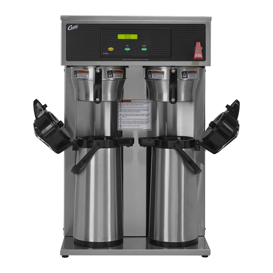
- Page 1 G3 D1000 Series Twin Airpot Coffee Brewing System : Please leave this booklet with the machine. 050217 FC29 - D1000, FRONT COVER F-10028 revNC...
-
Page 2: Table Of Contents
......................................................................................................................................................................Contact Information Wilbur Curtis Co., Inc. 6913 Acco Street | Montebello, CA 90640 US Phone: 323-837-2300 | Toll Free: 800-421-6150 Email: csrassistance@wilburcurtis.com | Web: www.wilburcurtis.com . - 4:00 . PT Email: techsupport@wilburcurtis.com D1000, CONTENTS LIST... -
Page 3: Fs29
KEY FEATURES/SPECIFICATIONS/SYSTEM REQUIREMENTS FS29 Key Features • Precise Gourmet Control Over All Critical Functions — The G3 Digital Control Module provides you the expertise to brew premium gourmet coffee with ease. • Cold water brew lockout prevents brewing when water temperature is below set level. •... -
Page 4: Is2
INSTRUCTIONS could result in personal injury or void the warranty. • This appliance is designed for commercial use. Any service other than cleaning and preventive maintenance should be performed by an authorized Wilbur Curtis service technician. • serviceable parts inside. - Page 5 IMPORTANT SAFEGUARDS CE Requirements • This appliance must be installed in locations where it can be overseen by trained personnel. • • • • This appliance must not be cleaned by water jet. • instruction concerning use of the appliance in a safe way and if they understand the hazards involved. •...
-
Page 6: Ii2
INSTALLATION INSTRUCTIONS WARNING: WARNING: properly grounded. NOTICE: SPECIFICATIONS section. IMPORTANT: Installation Instructions Installation Requirements • A secure surface capable of supporting the weight of the appliance. • For units without an attached cord set: Appropriately sized, UL listed, grounding type power cable to meet enough •... -
Page 7: Ii8
INSTALLATION INSTRUCTIONS Installation Leveling WARNING: Use the leveling legs to level the brewer only. Do not use them to adjust brewer height. Do not extend them higher than necessary. Position the brewer on the counter top. Level it left to right and front to back by turning the bottom of the legs. - Page 8 INSTALLATION INSTRUCTIONS Connect the Brewer Wiring (cont.) Brewers With A Cord Set Attached 12 Connect the power cord to the appropriate electrical outlet. WARNING: Connect the power cord to the appropriate type and size electrical outlet. If the electrical outlet is not compatible with the power cord, have it upgraded by a licensed electrician.
-
Page 9: Oi23
OPERATING INSTRUCTIONS OI23 Brewing Instructions WARNING - TO AVOID SCALDING, AVOID SPLASHING. Keep body parts clear of the brewer during brewing. Do not remove the brew basket while “Brewing” appears on the display. The G3 Brewer is factory preset for optimal performance. The brewer should be ON. -
Page 10: Ci1
CLEANING INSTRUCTIONS WARNING: HOT SURFACES - To avoid injury, allow the brewer and dispenser(s) to cool before cleaning. NOTICE - Do not use cleaning liquids, compounds or powders containing chlorine (bleach) or corrosives. USE OF THESE PRODUCTS WILL VOID THE WARRANTY. Cleaning The Brewer - Daily WARNING: DO NOT immerse the brewer in water or any other liquid. -
Page 11: Ci9
CLEANING INSTRUCTIONS Cleaning the Airpot/Pour Pot (Daily) WARNING: DO NOT immerse the airpot/pour pot or lid assembly in water or any other liquid. Do not place the airpot/pour pot or lid in a dishwasher. Placing a airpot or pour pot in a dishwasher will void the warranty. Start by preparing a mild solution of detergent and warm water. - Page 12 PROGRAMMING GUIDE Curtis To enter programming mode: With unit OFF, press and hold Entering bottom right BREW button (4). Programming mode Then press and release ON/OFF button. Continue to hold down BREW button until Enter Code appears. Enter 4 digit code.
- Page 13 PROGRAMMING GUIDE Programming Options Some menus save and exit automatically when a parameter is updated. Other menus exit to the previous menu when a parameter is saved. To exit, press until EXIT appears on the display, then press Brew by Volume - adjusts the volume brewed (the factory default is 74 oz (2.2L). With an empty airpot in place, press the appropriate BREW button.
- Page 14 Banner Name - changes the banner name that appears on the display (the factory default is Curtis). No banner name appears when all blanks are entered. Once accessed, press to choose the letter to change.
- Page 15 ROUGH-IN DRAWINGS RD35 D1000 Airpot Coffee Brewers 20.00 in [50.8 cm] 2.50 in 16.88 in [6.4 cm] [42.9 cm] Water Supply D1000GH D1000GH 29.25 in 26.38 in [74.3 cm] D1000GH D1000GH D1000GH [67.0 cm] 22.88 in 18.13 in D1000GT 17.13 in D1000GT [58.1 cm] [46.0 cm]...
- Page 16 ILLUSTRATED PARTS LIST IP51 Supplies and Accessories - All Models WC-29025 - Spray Head CAB-1 - Cleaning Brush D1000GT/ D1000GH - Main Chassis - Exploded View 1 1A Water tank assemblies: - 220 Volt, see section IP52 - Dual Voltage, see section IP53 1 1B D1000, ILLUSTRATED PARTS/RECOMMENDED PARTS 053117A...
- Page 17 TL9001/9002/SCTL9002 (OPTIONAL) HEATSINK, ASSY 1PH GEM612ILD GEM-12D/ LABEL, UCM OVERLAY DUAL D1000GT/H WC-8560 TL9002-10/D1000AP/T WC-39396 CURTIS LOGO (INCLUDES INNER AND OUTER LABEL) BREW CONE, W/HANDLE ASSY 7.1”D.W/WC- WC-3316 3317 & WC-3323 ALP/AP WC-8591 CAPACITOR, X2 USED ON ALL ADS MODELS BREW CONE, W/HANDLE ASSY 6.7”D DLX WC-...
- Page 18 ILLUSTRATED PARTS/RECOMMENDED PARTS IP52 WC-75285 - Tank Assembly WC-75285 - Tank Assembly - Parts List ITEM # PART # DESCRIPTION ITEM # PART # DESCRIPTION WC-75285 TANK, COMPLETE D1000GT/H W/ULTEM FITTINGS WC-4382 GUARD, SHOCK HTNG ELMNT DOUBLE WC-37008 KIT, TANK LID ROUND (INCLUDES GASKET) THERMOSTAT, HI LIMIT HEATER CONTROL DPST WC-522 277V 40A...
- Page 19 ILLUSTRATED PARTS/RECOMMENDED PARTS IP53 WC-75284 - Tank Assembly WC-75284 - Tank Assembly - Parts List ITEM # PART # DESCRIPTION ITEM # PART # DESCRIPTION TANK, COMPLETE D1000GT/H DV W/ULTEM WC-4382 GUARD, SHOCK HTNG ELMNT DOUBLE WC-75284 FITTINGS THERMOSTAT, HI LIMIT HEATER CONTROL DPST WC-522 WC-37008 KIT, TANK LID ROUND (INCLUDES GASKET)
- Page 20 ELECTRICAL SCHEMATICS ES53 D1000GT12, D1000GH13 D1000-10, ELECTRICAL SCHEMATIC 050217NC...
- Page 21 ELECTRICAL SCHEMATICS ES54 D1000GH62, D1000GT63 D1000-60, ELECTRICAL SCHEMATIC 050217NC...
- Page 22 TROUBLESHOOTING GUIDE WARNING: Electric Shock Hazard - Scald and Burn Hazard - IMPORTANT: always check all Valve Test Procedure Troubleshooting Guidelines • • • • Valve Test Procedure in either direction Water Not Hot Enough replace the temperature sensor Water Heats More Slowly Than Usual...
- Page 23 TROUBLESHOOTING GUIDE Water Does Not Heat At All Check to see if the water level in the tank is in contact with the water level probe. If not, see Tank Does Not Fill. • The water will not heat unless it is in contact with the probe. If the water heats, but is not hot enough, see Water Not Hot Enough.
- Page 24 ERROR CODES System Fault Messages An error message will appear on the screen in the event of a malfunction under the following conditions: ERROR MESSAGE WARNING DESCRIPTION CAUSE Water Level Error 1-(800)-000-0000 1-(800)-000-0000 1-(800)-000-0000...
- Page 25 Return Merchandise Authorization (RMA): All returned equipment must be properly re-packaged in the original carton and received by Curtis within 45 days following the issuance of a RMA. NO UNITS OR PARTS WILL BE ACCEPTED WITHOUT A RETURN MERCHANDISE AUTHORIZATION (RMA).